EP0604375A1 - Appui-bras pour sièges arrières de véhicules à moteur - Google Patents
Appui-bras pour sièges arrières de véhicules à moteur Download PDFInfo
- Publication number
- EP0604375A1 EP0604375A1 EP93830495A EP93830495A EP0604375A1 EP 0604375 A1 EP0604375 A1 EP 0604375A1 EP 93830495 A EP93830495 A EP 93830495A EP 93830495 A EP93830495 A EP 93830495A EP 0604375 A1 EP0604375 A1 EP 0604375A1
- Authority
- EP
- European Patent Office
- Prior art keywords
- armrest
- pivot pin
- distal
- elongated body
- proximal
- Prior art date
- Legal status (The legal status is an assumption and is not a legal conclusion. Google has not performed a legal analysis and makes no representation as to the accuracy of the status listed.)
- Granted
Links
Images


Classifications
-
- B—PERFORMING OPERATIONS; TRANSPORTING
- B60—VEHICLES IN GENERAL
- B60N—SEATS SPECIALLY ADAPTED FOR VEHICLES; VEHICLE PASSENGER ACCOMMODATION NOT OTHERWISE PROVIDED FOR
- B60N2/00—Seats specially adapted for vehicles; Arrangement or mounting of seats in vehicles
- B60N2/80—Head-rests
- B60N2/806—Head-rests movable or adjustable
-
- B—PERFORMING OPERATIONS; TRANSPORTING
- B60—VEHICLES IN GENERAL
- B60N—SEATS SPECIALLY ADAPTED FOR VEHICLES; VEHICLE PASSENGER ACCOMMODATION NOT OTHERWISE PROVIDED FOR
- B60N2/00—Seats specially adapted for vehicles; Arrangement or mounting of seats in vehicles
- B60N2/75—Arm-rests
- B60N2/753—Arm-rests movable to an inoperative position
- B60N2/757—Arm-rests movable to an inoperative position in a recess of the back-rest
-
- B—PERFORMING OPERATIONS; TRANSPORTING
- B60—VEHICLES IN GENERAL
- B60N—SEATS SPECIALLY ADAPTED FOR VEHICLES; VEHICLE PASSENGER ACCOMMODATION NOT OTHERWISE PROVIDED FOR
- B60N2/00—Seats specially adapted for vehicles; Arrangement or mounting of seats in vehicles
- B60N2/80—Head-rests
- B60N2/806—Head-rests movable or adjustable
- B60N2/874—Head-rests movable or adjustable movable to an inoperative or stowed position
Definitions
- the present invention refers in general to armrests for motor-vehicle seats, and is related in particular to a central armrest for a rear seat assembly having a seat cushion element and two back rest portions provided with respective top headrests and spaced-apart from each other so as to define an intermediate recess for the armrest.
- a central armrest for a rear seat assembly comprising an elongated body having one end provided with a mounting structure with a transverse pivot pin, which is intended to be supported by the two back rest portions in proximity to the seat cushion element so as to allow swinging of the armrest between a substantially horizontal lowered position and a substantially vertical raised position, and an opposite end having a headrest element, which is adapted to be used in said raised position of the armrest.
- the headrest element is formed by a cushion which is separated and distinct from the elongated body of the armrest and is slidably mounted, parallel to the longitudinal axis thereof and by means of a telescopic structure, between a retracted position and an advanced position.
- a cushion which is separated and distinct from the elongated body of the armrest and is slidably mounted, parallel to the longitudinal axis thereof and by means of a telescopic structure, between a retracted position and an advanced position.
- the two-part structure of this known central armrest has a complex construction, in particular due to the presence of the telescopic structure incorporated within the elongated body of the armrest for the sliding motion of the headrest element.
- a central armrest for a motor vehicle rear seat assembly is also known, which is swingable between a lowered and a raised position and carries at the free end thereof a headrest element which can be used in the raised position of the armrest.
- the headrest is formed by a body distinct from the armrest, but the vertical position thereof in the raised position of the armrest can not be modified.
- the object of the present invention is to overcome the drawbacks of the above mentioned known armrests and to provide a central armrest having a headrest element whose height, in the raised position of the armrest, can be adjusted by means of a construction adapted to be manufactured in a more simple and economical way.
- a further object of the invention is to provide a central armrest which, in the raised position of use of the headrest element, is adapted to enable higher safety and comfort for the user, accomplishing at the same time an additional effect of modifying the configuration of the rear seat assembly onto which same is applied in use, specifically consisting of increasing the rear loading capacity of the vehicle (in particular of sedan or station-wagon cars), and further allowing easy anchoring of a baby-seat or the like in the area of the central armrest.
- a central armrest of the above-referenced type the main feature of which resides in that the headrest element is formed in one piece with the elongated body of the armrest, and in that in said raised position the elongated body can be translated as a whole, relative to the mounting structure of the pivot pin, between a proximal condition and a distal condition corresponding to a minimum and, respectively, a maximum height of the headrest element.
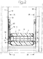
- reference numeral 1 generally designates a rear seat assembly of a motor-vehicle, comprising in a generally conventional way a seat cushion element 2 and two back rest portions 3 carrying at the top thereof respective headrests 4.
- the two back rest portions 3 are spaced-apart from each other so as to define a substantially vertical central recess 5, delimited inferiorly by the cushion element 2 and open upwardly, in correspondence of which a central armrest generally designated as 6 is positioned.
- the central armrest 6 is constituted by a single elongated body 7, normally made of foamed-plastic material incorporating in a way known per se a stiffening frame, provided at one end with a mounting structure for connection thereof to the sides of the back rest portions 3 facing towards the recess 5.
- This mounting structure is essentially constituted by a pair of lateral connecting plates 8 formed with respective substantially vertical slots 9 along which the ends of a transverse horizontal pin 10, on which the armrest 6 is swingably supported, are slidably fitted.
- the other end of the elongated body 7 is shaped as a headrest 11, formed integrally with and thus fixed relative to the body 7.
- the armrest 6 in the mounted condition of the two plates 8 the armrest 6 can swing around the axis of the pivot pin 10 between substantially horizontal lowered position, shown in dotted line in figures 1 and 3 and wherein it is extending above the seat cushion element 2 thus enabling arm resting for the passengers seated in correspondence of the back rest portions 3, and a substantially vertical raised position, shown in unbroken line in figures 1 and 3, wherein the armrest 6 is housed within the recess 5.
- a locking device known per se and not shown in detail in the drawings, which can be released by means of a tie rod mechanism 14 (figure 1), is provided for stopping the armrest 6 in either one of said lowered and raised positions so as to prevent undesired rotation thereof relative to the pivot pin 10.
- the pivot pin 10 is substantially positioned in correspondence of the lower portions of the slots 9 of the two plates 8, with the rear end of the elongated body 7 resting upon the intermediate element 12.
- the armrest 6 In the raised position, the armrest 6 can be displaced substantially vertically as a whole, through sliding of the ends of the pivot pin 10 along the slots 9 of the two plates 8, between a proximal condition in which it is adjacent to the cushion element 12 and the headrest element 11 is lowered with respect to the two headrests 4, and a distal position (shown with unbroken line in figures 1 and 3) in which the headrest element 11 is situated substantially at the same level of the two headrests 4.
- the elongated body 7 acts as a continuous and uninterrupted back rest for a central passenger, and the headrest element 11 can evidently be used as an adjustable headrest for such a passenger.
- the mounting structure (plates 8 and pivot pin 10) is conveniently provided with a disengageable locking device for maintaining in the raised position the elongated body 7 in either one of the proximal distal conditions, as will be disclosed herebelow.
- a through opening 13 is defined across the recess 5, between the cushion element 12, the sides of the back rest portions 3 and the lower end of the armrest 6, and along which, in the absence of a central passenger, any elongated article (for instance skies and the like) within the rear baggage compartment of the car, may be fitted.
- the passage 13 also enables firm and safe anchoring, by means of suitable quick connections not shown, of a baby seat.
- the pivot pin 10 extends through a tubular transverse portion 15 of the stiffening frame incorporated within the body 7 of the armrest 6 and has its opposite ends, projecting from the sides of the body 7, each formed by a reduced-section part 16a, 16b and by a terminal sliding block 17a, 17b, respectively. Both the reduced portions 16a, 16b and the terminal sliding blocks 17a, 17b have a substantially quadrangular cross-section, so as to prevent rotation of the pivot pin 10.
- Each of the two sliding blocks 17a, 17b is slidably mounted along the slot 9 of the corresponding plate 8, and these plates 8 are secured, for instance by means of screws, to the corresponding sides of the bearing structures 18 of the two back rest portions 3.
- the plate 8 slidably carrying the terminal sliding block 17a is provided with a locking push button 19 formed by a shaped plate defining forwardly two manoeuvring respectively upper and lower projections 20, 21, and rearwardly two stop respectively upper and lower heel members 22, 23.
- the plate 19 is formed with an open central slit 24 across which a transverse pivot pin 25 fixed to the plate 8 is fitted, with two intermediate open slits 26 placed on opposite sides with respect to the central slit 24 and across which respective transverse pins 27, also carried by the plate 8 are fitted, and with two outer closed slots 28 across which respective transverse pins 29 also carried by the plate 8 are fitted.
- the slot 9 of the other plate 8 i.e. the one along which the other sliding block 17b is slidable, is provided at its opposite ends with a pair of resilient snap-positioning respectively lower and upper formations 32 and 33.
- Figures 5 and 6 show the position of the terminal sliding blocks 17a, 17b in the proximal condition of the body 7 of the armrest 6. In this position the sliding blocks 17a and 17b are positioned at the lower ends of the respective slots 9, with the sliding block 17a locked by the lower heel stop 23 of the plate 19, and the sliding block 17b held within the lower formation 32.
- the upper heel stop 22 snap-engages below the sliding block 17a, while the other sliding block 17b snap fits within the upper formation 33.
- the conformation of the locking plate 9 may be different from the illustrated one, and can for instance be designed so as to allow positioning of the body 7 also in one intermediate position comprised between the proximal and distal conditions, or even allow a step-adjustment of the height thereof.
Landscapes
- Engineering & Computer Science (AREA)
- Aviation & Aerospace Engineering (AREA)
- Transportation (AREA)
- Mechanical Engineering (AREA)
- Seats For Vehicles (AREA)
Applications Claiming Priority (2)
| Application Number | Priority Date | Filing Date | Title |
|---|---|---|---|
| ITTO921026 | 1992-12-21 | ||
| ITTO921026A IT1257946B (it) | 1992-12-21 | 1992-12-21 | Bracciolo posteriore centrale con appoggiatesta per autoveicoli. |
Publications (2)
| Publication Number | Publication Date |
|---|---|
| EP0604375A1 true EP0604375A1 (fr) | 1994-06-29 |
| EP0604375B1 EP0604375B1 (fr) | 1996-05-01 |
Family
ID=11410932
Family Applications (1)
| Application Number | Title | Priority Date | Filing Date |
|---|---|---|---|
| EP93830495A Expired - Lifetime EP0604375B1 (fr) | 1992-12-21 | 1993-12-10 | Appui-bras pour sièges arrières de véhicules à moteur |
Country Status (5)
| Country | Link |
|---|---|
| US (1) | US5433503A (fr) |
| EP (1) | EP0604375B1 (fr) |
| DE (1) | DE69302462T2 (fr) |
| ES (1) | ES2086212T3 (fr) |
| IT (1) | IT1257946B (fr) |
Cited By (9)
| Publication number | Priority date | Publication date | Assignee | Title |
|---|---|---|---|---|
| FR2735732A1 (fr) * | 1995-06-26 | 1996-12-27 | Faure Bertrand Equipements Sa | Accoudoir rabattable, et siege de vehicule equipe d'un tel accoudoir |
| WO1998021065A1 (fr) | 1996-11-11 | 1998-05-22 | F.S. Fehrer Gmbh & Co. Kg | Banquette de vehicule comportant un accoudoir et un appui-tete |
| WO1999006239A1 (fr) | 1997-08-01 | 1999-02-11 | Industrias Esteban, S.A. | Ameliorations apportees aux sieges d'autocars |
| EP0943483A3 (fr) * | 1998-03-20 | 2001-08-16 | Adam Opel Ag | Agencement d'au moins deux sièges adjacents |
| FR2896737A1 (fr) * | 2006-01-31 | 2007-08-03 | Peugeot Citroen Automobiles Sa | Systeme de support mobile et siege comportant un tel systeme |
| WO2008007988A1 (fr) * | 2006-07-13 | 2008-01-17 | Gestind Poland Sp. Zo.O | Charnière permettant de fixer des éléments de l'habitacle d'un véhicule à moteur |
| US20120104822A1 (en) * | 2010-10-27 | 2012-05-03 | Hans Henke | Supporting Structure For A Swivelable Center Armrest |
| RU2478491C2 (ru) * | 2008-01-14 | 2013-04-10 | Джи Эм Глоубал Текнолоджи Оперейшнз, Инк. | Система сиденья с двумя сиденьями транспортного средства в одном ряду сидений |
| CN104417409A (zh) * | 2013-09-03 | 2015-03-18 | 铃木株式会社 | 座椅靠背 |
Families Citing this family (33)
| Publication number | Priority date | Publication date | Assignee | Title |
|---|---|---|---|---|
| US5848820A (en) * | 1997-06-27 | 1998-12-15 | Lear Corporation | Pivotable rear seat center cushion assembly with utility compartment |
| US5947554A (en) * | 1997-12-17 | 1999-09-07 | Chrysler Corporation | Seat assembly with center adjustable height armrest |
| US6213546B1 (en) * | 1999-11-24 | 2001-04-10 | Johnson Controls Technology Company | Sliding actuation armrest |
| US6471297B1 (en) | 2000-08-25 | 2002-10-29 | Magna Seating Systems, Inc. | Pivotal and retractable armrest assembly |
| US6918160B1 (en) * | 2001-06-06 | 2005-07-19 | Tecla Company, Inc. | Fold-up marine furniture component with articulated bracket support |
| US6767056B2 (en) * | 2002-01-14 | 2004-07-27 | Shin Yeh Enterprise Co., Ltd. | Settee with a foldable tray-support unit |
| US7178865B2 (en) * | 2004-09-24 | 2007-02-20 | Lear Corporation | Center occupant armrest actuated head restraint |
| US7484808B2 (en) * | 2005-04-04 | 2009-02-03 | Lear Corporation | Vision improving system for a head restraint |
| US8152242B2 (en) * | 2005-04-04 | 2012-04-10 | Lear Corporation | Selective remote head restraint actuation |
| DE202005021378U1 (de) * | 2005-09-29 | 2007-11-22 | Faurecia Autositze Gmbh | Sitzreihe eines Kraftfahrzeugs mit einer zwischen zwei Außensitzen angeordneten Armlehne |
| DE102006010376A1 (de) * | 2006-03-03 | 2007-09-06 | Bos Gmbh & Co. Kg | Rücksitzlehne mit höhenverstellbarer Mittelarmlehne |
| CN101674952A (zh) * | 2007-05-18 | 2010-03-17 | 麦格纳座椅公司 | 可展开的中央扶手 |
| US8186760B2 (en) | 2008-10-31 | 2012-05-29 | The Boeing Company | Adjustable width seats |
| CA2759128C (fr) | 2009-03-12 | 2016-09-20 | Magna Seating Inc. | Mecanisme de levage et de rotation a fente unique |
| US9758075B2 (en) * | 2009-03-27 | 2017-09-12 | Lear Corporation | Seat assembly having an armrest |
| GB2469310B (en) * | 2009-04-08 | 2013-11-06 | Ford Global Tech Llc | A seat having an armrest assembly |
| JP5691872B2 (ja) * | 2011-06-20 | 2015-04-01 | スズキ株式会社 | シートバック |
| JP5773193B2 (ja) * | 2011-07-11 | 2015-09-02 | スズキ株式会社 | シートバック |
| GB2508607A (en) | 2012-12-04 | 2014-06-11 | Ford Global Tech Llc | A seating arrangement for a passenger vehicle |
| GB2519309B (en) | 2013-10-16 | 2019-07-10 | Ford Global Tech Llc | A motor vehicle seating arrangement having an armrest |
| US9440584B2 (en) | 2013-11-21 | 2016-09-13 | Ford Global Technologies, Llc | Photoluminescent vehicle console |
| US9676305B2 (en) * | 2014-08-18 | 2017-06-13 | Tum Create Limited | Vehicle seat with integrated child seat |
| US10259368B2 (en) * | 2015-07-24 | 2019-04-16 | Textron Innovations Inc. | Articulating armrest |
| KR101738052B1 (ko) * | 2015-12-04 | 2017-05-19 | 현대자동차주식회사 | 암레스트의 잠금구조 |
| DE102016011331B4 (de) * | 2016-09-21 | 2022-09-15 | Grammer Aktiengesellschaft | Armlehne |
| US10160392B2 (en) | 2017-01-31 | 2018-12-25 | Ford Global Technologies, Llc | Composite seat side storage bin |
| JP6488326B2 (ja) * | 2017-03-09 | 2019-03-20 | テイ・エス テック株式会社 | 乗物用シート |
| WO2019005880A1 (fr) | 2017-06-27 | 2019-01-03 | Shanghai Yanfeng Jinqiao Automotive Trim Systems Co. Ltd. | Composant d'intérieur de véhicule |
| US10227027B2 (en) * | 2017-06-30 | 2019-03-12 | Lear Corporation | Seat back with pivotable armrest and armrest restrictor |
| US10882427B2 (en) * | 2017-09-27 | 2021-01-05 | Gulfstream Aerospace Corporation | Seat assembly including an armrest sub-assembly and method for fabricating the same |
| US10829020B2 (en) * | 2018-02-01 | 2020-11-10 | Ford Global Technologies, Llc | Vehicle seating arrangement |
| US10737602B2 (en) * | 2018-11-07 | 2020-08-11 | Ford Global Technologies, Llc | Deployable armrest |
| CN110774958B (zh) * | 2019-11-28 | 2024-01-12 | 安道拓(重庆)汽车部件有限公司 | 车用后排座椅中央扶手骨架总成 |
Citations (7)
| Publication number | Priority date | Publication date | Assignee | Title |
|---|---|---|---|---|
| US1896477A (en) * | 1929-07-17 | 1933-02-07 | Boller Alexander | Back seat for automobiles |
| US3343875A (en) * | 1965-10-06 | 1967-09-26 | Gen Motors Corp | Adjustable seat back headrest |
| GB1229947A (fr) * | 1968-11-07 | 1971-04-28 | ||
| JPS62134340A (ja) * | 1985-12-05 | 1987-06-17 | Nippon Soken Inc | 車両用シ−ト |
| DE4015872C1 (en) * | 1990-05-17 | 1992-01-02 | Bayerische Motoren Werke Ag, 8000 Muenchen, De | Rear seat for motor vehicle - has headrest connected to top of armrest for selective use |
| DE4225880A1 (de) * | 1991-08-14 | 1993-02-18 | Volkswagen Ag | Sitzanordnung mit einem wahlweise als armlehne oder kopfstuetze zu benutzenden polsterelement |
| EP0571097A1 (fr) * | 1992-05-22 | 1993-11-24 | Jaguar Cars Limited | Sièges de véhicule |
Family Cites Families (6)
| Publication number | Priority date | Publication date | Assignee | Title |
|---|---|---|---|---|
| US3254915A (en) * | 1965-03-03 | 1966-06-07 | Robert J Mahaffey | Car seat |
| US3374032A (en) * | 1967-02-13 | 1968-03-19 | Hardman Tool And Engineering C | Aircraft seat |
| US4176878A (en) * | 1978-04-24 | 1979-12-04 | Sears Manufacturing Company | Armrest structure |
| US4533175A (en) * | 1983-12-23 | 1985-08-06 | Ptc Aerospace Inc. | Convertible seat |
| JPS6338046A (ja) * | 1986-07-31 | 1988-02-18 | Mazda Motor Corp | 車両用シ−トのア−ムレスト |
| JPH0378454U (fr) * | 1989-11-29 | 1991-08-08 |
-
1992
- 1992-12-21 IT ITTO921026A patent/IT1257946B/it active IP Right Grant
-
1993
- 1993-12-10 DE DE69302462T patent/DE69302462T2/de not_active Expired - Fee Related
- 1993-12-10 ES ES93830495T patent/ES2086212T3/es not_active Expired - Lifetime
- 1993-12-10 EP EP93830495A patent/EP0604375B1/fr not_active Expired - Lifetime
- 1993-12-21 US US08/170,860 patent/US5433503A/en not_active Expired - Fee Related
Patent Citations (7)
| Publication number | Priority date | Publication date | Assignee | Title |
|---|---|---|---|---|
| US1896477A (en) * | 1929-07-17 | 1933-02-07 | Boller Alexander | Back seat for automobiles |
| US3343875A (en) * | 1965-10-06 | 1967-09-26 | Gen Motors Corp | Adjustable seat back headrest |
| GB1229947A (fr) * | 1968-11-07 | 1971-04-28 | ||
| JPS62134340A (ja) * | 1985-12-05 | 1987-06-17 | Nippon Soken Inc | 車両用シ−ト |
| DE4015872C1 (en) * | 1990-05-17 | 1992-01-02 | Bayerische Motoren Werke Ag, 8000 Muenchen, De | Rear seat for motor vehicle - has headrest connected to top of armrest for selective use |
| DE4225880A1 (de) * | 1991-08-14 | 1993-02-18 | Volkswagen Ag | Sitzanordnung mit einem wahlweise als armlehne oder kopfstuetze zu benutzenden polsterelement |
| EP0571097A1 (fr) * | 1992-05-22 | 1993-11-24 | Jaguar Cars Limited | Sièges de véhicule |
Non-Patent Citations (1)
| Title |
|---|
| PATENT ABSTRACTS OF JAPAN vol. 11, no. 356 (M - 644) 20 November 1987 (1987-11-20) * |
Cited By (14)
| Publication number | Priority date | Publication date | Assignee | Title |
|---|---|---|---|---|
| EP0751037A1 (fr) * | 1995-06-26 | 1997-01-02 | Bertrand Faure Equipements S.A. | Accoudoir rabattable pour siège de véhicule |
| FR2735732A1 (fr) * | 1995-06-26 | 1996-12-27 | Faure Bertrand Equipements Sa | Accoudoir rabattable, et siege de vehicule equipe d'un tel accoudoir |
| DE19781265B4 (de) * | 1996-11-11 | 2004-09-16 | F.S. Fehrer Gmbh & Co. Kg | Fahrzeugrücksitzbank mit Mittelarmlehne und Kopfstütze |
| WO1998021065A1 (fr) | 1996-11-11 | 1998-05-22 | F.S. Fehrer Gmbh & Co. Kg | Banquette de vehicule comportant un accoudoir et un appui-tete |
| US6217112B1 (en) | 1996-11-11 | 2001-04-17 | F. S. Fehrer Gmbh & Co. Kg | Motor vehicle seat bench with middle arm rest and head |
| WO1999006239A1 (fr) | 1997-08-01 | 1999-02-11 | Industrias Esteban, S.A. | Ameliorations apportees aux sieges d'autocars |
| EP0943483A3 (fr) * | 1998-03-20 | 2001-08-16 | Adam Opel Ag | Agencement d'au moins deux sièges adjacents |
| FR2896737A1 (fr) * | 2006-01-31 | 2007-08-03 | Peugeot Citroen Automobiles Sa | Systeme de support mobile et siege comportant un tel systeme |
| WO2008007988A1 (fr) * | 2006-07-13 | 2008-01-17 | Gestind Poland Sp. Zo.O | Charnière permettant de fixer des éléments de l'habitacle d'un véhicule à moteur |
| DE112007001634T5 (de) | 2006-07-13 | 2009-07-02 | Gestind Poland Sp. Z O.O. | Scharnier zur Befestigung von Innenraumteilen von Kraftfahrzeugen |
| RU2478491C2 (ru) * | 2008-01-14 | 2013-04-10 | Джи Эм Глоубал Текнолоджи Оперейшнз, Инк. | Система сиденья с двумя сиденьями транспортного средства в одном ряду сидений |
| US20120104822A1 (en) * | 2010-10-27 | 2012-05-03 | Hans Henke | Supporting Structure For A Swivelable Center Armrest |
| US8960786B2 (en) * | 2010-10-27 | 2015-02-24 | F.S. Fehrer Automotive Gmbh | Supporting structure for a swivelable center armrest |
| CN104417409A (zh) * | 2013-09-03 | 2015-03-18 | 铃木株式会社 | 座椅靠背 |
Also Published As
| Publication number | Publication date |
|---|---|
| ITTO921026A0 (it) | 1992-12-21 |
| IT1257946B (it) | 1996-02-19 |
| DE69302462T2 (de) | 1996-12-05 |
| US5433503A (en) | 1995-07-18 |
| ES2086212T3 (es) | 1996-06-16 |
| DE69302462D1 (de) | 1996-06-05 |
| EP0604375B1 (fr) | 1996-05-01 |
| ITTO921026A1 (it) | 1994-06-21 |
Similar Documents
| Publication | Publication Date | Title |
|---|---|---|
| EP0604375B1 (fr) | Appui-bras pour sièges arrières de véhicules à moteur | |
| EP1358088B1 (fr) | Ensemble siege de vehicule equipe d'un appui-tete a autopositionnement commande par came | |
| US6074011A (en) | Automatic retractable head restraint | |
| US5951084A (en) | Seat structure for a vehicle | |
| US7533934B2 (en) | Vehicle seat | |
| US5700054A (en) | Vehicle seat assembly including integral child restraint seat | |
| EP0594543B1 (fr) | Appui-tête pour sièges de véhicule automobile, en particulier pour sièges arrière | |
| EP0976608A1 (fr) | Appui-tête pour siège de véhicules automobiles. | |
| WO2003106214A1 (fr) | Ensemble siege muni d'un appui-tete/cou integre | |
| CN120863435A (zh) | 儿童安全座椅 | |
| US20020060487A1 (en) | Seat displacement mechanism for a seat with tilting back | |
| US6533341B2 (en) | Adjustable pivoting means for a vehicle seat backrest | |
| EP0819568A2 (fr) | Appui-tête pour sièges de véhicules automobiles | |
| CN108725272B (zh) | 用于h点举升的可折叠举升机构 | |
| EP0713800B1 (fr) | Siège arrière pour véhicules automobiles | |
| EP0068322B1 (fr) | Système de ceinture de sécurité automatique pour un véhicule automobile comportant des sièges basculants | |
| JP3417109B2 (ja) | 車両用シート | |
| JPH05301560A (ja) | シートベルトのスルーガイド構造 | |
| KR100449292B1 (ko) | 자동차의 콘솔 | |
| EP0226557B1 (fr) | Siège pour véhicules automobiles | |
| KR200159427Y1 (ko) | 수평조절식 헤드 레스트 | |
| CN101107147B (zh) | 用于机动车辆座椅的靠背装置 | |
| EP0925994A1 (fr) | Appui-tête pour sièges de véhicules automobiles | |
| EP0310572B1 (fr) | Siège rabattable, particulièrement pour véhicule à moteur | |
| JPH1016707A (ja) | 車両用シートのヘッドレスト及びシートベルトの高さ調節機構 |
Legal Events
| Date | Code | Title | Description |
|---|---|---|---|
| PUAI | Public reference made under article 153(3) epc to a published international application that has entered the european phase |
Free format text: ORIGINAL CODE: 0009012 |
|
| AK | Designated contracting states |
Kind code of ref document: A1 Designated state(s): DE ES FR GB IT SE |
|
| 17P | Request for examination filed |
Effective date: 19941026 |
|
| 17Q | First examination report despatched |
Effective date: 19950802 |
|
| GRAH | Despatch of communication of intention to grant a patent |
Free format text: ORIGINAL CODE: EPIDOS IGRA |
|
| GRAA | (expected) grant |
Free format text: ORIGINAL CODE: 0009210 |
|
| AK | Designated contracting states |
Kind code of ref document: B1 Designated state(s): DE ES FR GB IT SE |
|
| ITF | It: translation for a ep patent filed | ||
| REF | Corresponds to: |
Ref document number: 69302462 Country of ref document: DE Date of ref document: 19960605 |
|
| REG | Reference to a national code |
Ref country code: ES Ref legal event code: FG2A Ref document number: 2086212 Country of ref document: ES Kind code of ref document: T3 |
|
| ET | Fr: translation filed | ||
| PLBE | No opposition filed within time limit |
Free format text: ORIGINAL CODE: 0009261 |
|
| STAA | Information on the status of an ep patent application or granted ep patent |
Free format text: STATUS: NO OPPOSITION FILED WITHIN TIME LIMIT |
|
| 26N | No opposition filed | ||
| PGFP | Annual fee paid to national office [announced via postgrant information from national office to epo] |
Ref country code: ES Payment date: 20001221 Year of fee payment: 8 |
|
| PGFP | Annual fee paid to national office [announced via postgrant information from national office to epo] |
Ref country code: SE Payment date: 20001227 Year of fee payment: 8 Ref country code: GB Payment date: 20001227 Year of fee payment: 8 Ref country code: FR Payment date: 20001227 Year of fee payment: 8 |
|
| PGFP | Annual fee paid to national office [announced via postgrant information from national office to epo] |
Ref country code: DE Payment date: 20010223 Year of fee payment: 8 |
|
| PG25 | Lapsed in a contracting state [announced via postgrant information from national office to epo] |
Ref country code: GB Free format text: LAPSE BECAUSE OF NON-PAYMENT OF DUE FEES Effective date: 20011210 |
|
| PG25 | Lapsed in a contracting state [announced via postgrant information from national office to epo] |
Ref country code: SE Free format text: LAPSE BECAUSE OF NON-PAYMENT OF DUE FEES Effective date: 20011211 |
|
| REG | Reference to a national code |
Ref country code: GB Ref legal event code: IF02 |
|
| PG25 | Lapsed in a contracting state [announced via postgrant information from national office to epo] |
Ref country code: DE Free format text: LAPSE BECAUSE OF NON-PAYMENT OF DUE FEES Effective date: 20020702 |
|
| EUG | Se: european patent has lapsed |
Ref document number: 93830495.3 |
|
| GBPC | Gb: european patent ceased through non-payment of renewal fee |
Effective date: 20011210 |
|
| PG25 | Lapsed in a contracting state [announced via postgrant information from national office to epo] |
Ref country code: FR Free format text: LAPSE BECAUSE OF NON-PAYMENT OF DUE FEES Effective date: 20020830 |
|
| REG | Reference to a national code |
Ref country code: FR Ref legal event code: ST |
|
| PG25 | Lapsed in a contracting state [announced via postgrant information from national office to epo] |
Ref country code: ES Free format text: LAPSE BECAUSE OF NON-PAYMENT OF DUE FEES Effective date: 20021211 |
|
| REG | Reference to a national code |
Ref country code: ES Ref legal event code: FD2A Effective date: 20030113 |
|
| PG25 | Lapsed in a contracting state [announced via postgrant information from national office to epo] |
Ref country code: IT Free format text: LAPSE BECAUSE OF NON-PAYMENT OF DUE FEES;WARNING: LAPSES OF ITALIAN PATENTS WITH EFFECTIVE DATE BEFORE 2007 MAY HAVE OCCURRED AT ANY TIME BEFORE 2007. THE CORRECT EFFECTIVE DATE MAY BE DIFFERENT FROM THE ONE RECORDED. Effective date: 20051210 |