EP0604384B1 - Vorlagenhalter - Google Patents
Vorlagenhalter Download PDFInfo
- Publication number
- EP0604384B1 EP0604384B1 EP93890235A EP93890235A EP0604384B1 EP 0604384 B1 EP0604384 B1 EP 0604384B1 EP 93890235 A EP93890235 A EP 93890235A EP 93890235 A EP93890235 A EP 93890235A EP 0604384 B1 EP0604384 B1 EP 0604384B1
- Authority
- EP
- European Patent Office
- Prior art keywords
- copy
- bearing
- holder according
- rails
- arms
- Prior art date
- Legal status (The legal status is an assumption and is not a legal conclusion. Google has not performed a legal analysis and makes no representation as to the accuracy of the status listed.)
- Expired - Lifetime
Links
- 230000002093 peripheral effect Effects 0.000 claims description 2
- 239000011796 hollow space material Substances 0.000 abstract 1
- 238000004519 manufacturing process Methods 0.000 description 8
- 239000000969 carrier Substances 0.000 description 3
- 230000002349 favourable effect Effects 0.000 description 3
- 238000003780 insertion Methods 0.000 description 3
- 230000037431 insertion Effects 0.000 description 3
- 238000010276 construction Methods 0.000 description 2
- 238000005520 cutting process Methods 0.000 description 2
- 238000003860 storage Methods 0.000 description 2
- 238000002347 injection Methods 0.000 description 1
- 239000007924 injection Substances 0.000 description 1
- 238000003825 pressing Methods 0.000 description 1
Images


Classifications
-
- G—PHYSICS
- G09—EDUCATION; CRYPTOGRAPHY; DISPLAY; ADVERTISING; SEALS
- G09F—DISPLAYING; ADVERTISING; SIGNS; LABELS OR NAME-PLATES; SEALS
- G09F11/00—Indicating arrangements for variable information in which the complete information is permanently attached to a movable support which brings it to the display position
- G09F11/30—Indicating arrangements for variable information in which the complete information is permanently attached to a movable support which brings it to the display position the display elements being fed one by one from storage place to a display position
-
- A—HUMAN NECESSITIES
- A47—FURNITURE; DOMESTIC ARTICLES OR APPLIANCES; COFFEE MILLS; SPICE MILLS; SUCTION CLEANERS IN GENERAL
- A47F—SPECIAL FURNITURE, FITTINGS, OR ACCESSORIES FOR SHOPS, STOREHOUSES, BARS, RESTAURANTS OR THE LIKE; PAYING COUNTERS
- A47F5/00—Show stands, hangers, or shelves characterised by their constructional features
- A47F5/0081—Show stands or display racks with movable parts
- A47F5/0087—Show stands or display racks with movable parts movable around an axis
-
- G—PHYSICS
- G09—EDUCATION; CRYPTOGRAPHY; DISPLAY; ADVERTISING; SEALS
- G09F—DISPLAYING; ADVERTISING; SIGNS; LABELS OR NAME-PLATES; SEALS
- G09F15/00—Boards, hoardings, pillars, or like structures for notices, placards, posters, or the like
- G09F15/0087—Boards, hoardings, pillars, or like structures for notices, placards, posters, or the like including movable parts, e.g. movable by the wind
Definitions
- the invention relates to a template holder with a plurality of template receiving frames, which with pivoting, mutually parallel geometric pivot axes, which preferably run approximately perpendicularly, are pivotably mounted on a stand in two support rails running approximately transversely to the pivot axes and in the manner of leaves Book are movable.
- Known template holders of the type mentioned above for example GB-A-2 124 475, have support rails which are designed in the form of angle rails, each of these angle rails having in its one leg a series of bearing bores or holes into which axle journals are inserted, which Templates frame are arranged.
- the two mounting rails provided with the holes are arranged with the flat sides of the legs of the mounting rails provided with the holes, and there are two axially aligned axle journals on each template receiving frame on one side thereof, which likewise align mutually aligned holes in the two oppositely arranged mounting rails are inserted so that the template receiving frame is pivotally mounted.
- the template holder according to the invention of the type mentioned at the outset is characterized in that the mounting rails are provided with a hollow profile rails which lead from the outside into the cavity and have longitudinal slots, and in the cavities located in the two mounting rails are successively inserted bearing bodies over the longitudinal extent of the mounting rails, which by their shape can be inserted into the cavity of the mounting rails in their longitudinal direction and are held transversely to the longitudinal direction of the mounting rails in this cavity, with each template receiving frame in each of the two mounting rails being assigned a respective bearing body and one of each of these bearing bodies using the relevant bearing body in the relevant mounting rail pivots mounted arm, which protrudes through the longitudinal slot in the mounting rail and which is connected at its outer end to the template receiving frame associated with the bearing body in question.
- the support rails of the template holder can be produced by simply cutting hollow profile rods to length, with no holes having to be made to form the swivel bearing points for the template receiving frame; the length of the mounting rails can be chosen as desired, in accordance with the particular requirements at hand, without this being associated with any additional effort for cutting to length; the assembly of the template holder designed according to the invention is very simple since the arms provided bearing body, which can already be connected to the template-receiving frame, or can also be molded onto this template-receiving frame, simply in the longitudinal direction of the mounting rails from the open end face, which has been formed by the cross-cuts, can be inserted in succession. It is determined by the size of the bearing body, the mutual distance between the pivot axes of adjacent template receiving frames.
- the arms are firmly connected to the bearing bodies. It is particularly advantageous in terms of parts production and also in terms of stability if one provides that the arms are integrated in one piece with the bearing bodies.
- a variant, which can achieve particularly low friction at the pivot bearing points, is characterized in that bearing recesses are provided in the bearing bodies, into which bearing pins provided on the arms engage to form a pivot bearing for the arms.
- the bearing bodies are, from a geometric point of view, rotational bodies.
- a functionally favorable and in terms of good guiding properties for the template receiving frame stored with these bearing bodies is obtained when the bearing body is approximately circular cylindrical disc-shaped. Due to a spherical design of the bearing body, the friction occurring during the pivoting movement of the template receptacles can be kept very low.
- a groove can advantageously be provided in the center on the circumferential surface of the bearing body in order to reduce the friction which occurs during the pivoting movement of the template receiving frame, which has a particularly favorable effect in the case of a circular cylindrical design of the bearing body.
- bearing pins provided on the arms are movably mounted in the bearing bodies, it is advantageous in the sense of achieving the most precise possible geometry of the pivot bearing for the template receiving frame if the bearing bodies are approximately cuboid.
- the template receiving frames at the end of their flip-over movement which are used to select the desired template receiving frame from the entirety of the template receiving frames provided on a template holder is executed, assume substantially the same angular position with respect to the mounting rails; It is also advantageous if there is a small mutual distance between the individual template mounting frames in this position on the viewer side, which allows the individual template mounting frames to be grasped in order to carry out further flip-over operations, such as are carried out to locate additional templates or information carriers need to be relieved.
- An advantageous embodiment of the template holder according to the invention which is able to take these desires into account in a simple manner, is characterized in that the distance in the longitudinal direction of the mounting rails is determined by the geometrical pivot axes of the template receiving frames determined by the bearing bodies and the distance between them determined by the arms Geometric pivot axes and the side of the template receiving frame facing the mounting rails is selected so that the template receiving frame when pivoting into end positions inclined to the longitudinal direction of the mounting rail with a mutual distance between the template-receiving frame come to rest on at least one mounting rail.
- An embodiment in which a structurally simple manner an exact guidance of the arms supporting the template receiving frame can be achieved is characterized in that bearing pins are provided on the bearing bodies, on opposite sides thereof, and that these bearing pins correspond in the Support rails starting from a central cavity, a longitudinal groove and the slot leading to the outside are arranged.
- bearing pins are provided on the bearing bodies, on opposite sides thereof, and that corresponding to these bearing pins, a longitudinal groove and a further longitudinal groove are provided in the mounting rails starting from a central cavity and the longitudinal slot, through which the arms protrude outwards, leads outwards across the geometric swivel axes.
- the two mounting rails form an integral profile together with a connecting wall.
- a nice appearance of the document holder with a closed surface which can be easily cleaned can also be obtained in a relatively simple manner.
- a variant here, which can be realized with smaller profile cross-sections, and in which a relatively compact structure can also be obtained, is characterized in that the two mounting rails are connected to a mounting frame with connecting brackets which engage at the ends of the mounting rails in their cavities are.
- a plurality of template receiving frames 2 are provided which, with mutually parallel, mutually parallel geometric pivot axes 3, which preferably run approximately perpendicular, run in two approximately transverse to the pivot axes 3
- Support rails 4 are pivotally mounted and movable in the manner of the leaves of a book, as indicated by double arrows 5. In this way, a viewer who looks in the direction of arrow 7 (FIG.
- the support rails 4 are attached to a stand 6, not shown, or part of such a stand.
- the support rails 4 are hollow profile rails which are provided with a slot 10 leading from the outside into their cavity 9.
- bearing bodies 12 are successively inserted over the longitudinal extent 11 of the mounting rails 4, the shape of which is selected such that they can be inserted in the longitudinal direction 13 of the mounting rails 4 into the cavity 9 and in a direction transverse to the longitudinal direction 13 Direction 14 are held in this cavity 9.
- Each template-receiving frame 2 is assigned a bearing body 12 in each of the two mounting rails 4, and each of these mounting bodies 12 is provided with an arm 15 pivotably mounted by means of the bearing body in question in the mounting rail 4 in question, which passes through the longitudinal slot 10 in FIG Carrier rail 4 protrudes outwards and is connected at its outer end 16 to the template receiving frame 2 assigned to the bearing body 12 in question.
- the arms 15 are firmly connected to the template receiving frame 2, which e.g. can be realized by a welded connection or also by a riveted connection; a preferred embodiment provides that the template-receiving frame 2 are integrally integrated with the arms 15, in particular in the form of an integrated plastic injection molded part.
- the arms 15 are also firmly connected to the bearing bodies 12, in particular integrated in one piece, so that the bearing bodies 15 are in firm connection with the template receiving frame 2, and are therefore also particularly easy to handle if they come from an open end 17 of the mounting rails 4 are successively inserted into the cavity 9 of the mounting rails 4. This open end 17 is then closed, for example with a stopper 32.
- the two arms 15, which are provided on each template-receiving frame 2 are also connected to one another via a bar 15b, as a result of which great stability is achieved. But it is also possible to omit this bar 15b.
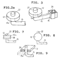
- the bearing body 12, which is well suited to the invention, with an arm 15 provided for connection to a template receiving frame 2 is shown in an oblique view in FIG. 2a.
- the bearing bodies 12, viewed geometrically, are rotational bodies, and the geometrical pivot axes 3 are thereby kept at a constant distance 18 when the template receiving frames 2 are pivoted by the bearing bodies 12, which lie slightly against one another .
- the bearing bodies 12 are designed in the form of approximately circular cylindrical disks, as is also the case in the embodiment according to FIG. 2a.
- the distance 18 present in the longitudinal direction of the mounting rails 4 of the geometric pivot axes 3 determined by the bearing bodies 12, about which the bearing bodies 12 and thus also the template receiving frames 2 pivot, and the distance between the geometric pivot axes 3 and that determined by the arms 15 Support rails 4 facing side 19 of the template mounting frame 2 is selected so that the template mounting frame when pivoting according to the arrows 5 in end positions inclined to the longitudinal direction of the mounting rails, as assumed by the template mounting frame designated by 2a, with a mutual distance 20 between them Template receiving frame 2 come to rest on at least one mounting rail 4.
- the slots 10 provided in the mounting rails 4 lie on the mutually facing sides 21 of the mounting rails 4 and the arms 15 with their sections 15a form bearing journals which protrude through these slots. In this way, a positionally stable pivot bearing is created.
- bearing pins 22 are also provided on the sides 12a lying opposite to the sections 15a of the arms 15, which engage in a matching longitudinal groove 23 which is provided in the mounting rails 4.
- the mounting rails 4 form in the embodiment shown in FIGS. 1 and 2 together with connecting plates 24, 25 a one-piece profile. This results in a stable structure, and it is particularly advantageous for inserting the bearing body 12 into the mounting rails 4.
- Fig. 3 shows a component consisting of bearing body 12 and arm 15, which carries at its end 16 a clip-like clamp 26, which serves to connect the arm 15 to the template receiving frame 2, this connection can be released if desired.
- a releasable connection makes it possible to remove individual template holding frames from the template holder, and one can thus, if desired, exchange individual template holding frames for other, possibly color-different frames, size-different frames or shape-different frames or the insertion of templates or information carriers into the template Make the frame in the removed state of the same.
- Fig. 4 shows a variant of the embodiment according to FIGS. 1 and 2, in which the slot 10, which leads from the cavities 9 in the mounting rails 4 to the outside and through which the arms 15 extend with their sections 15a, facing away from each other Sides of the two mounting rails 4 is placed.
- the longitudinal slot 10 leads outwards from the cavity 9 of the mounting rails 4 transversely to the geometric pivot axes 3 of the bearing bodies 12. It is thus the storage of the bearing body 12 in the mounting rails 4 largely independent of the arms 15 leading from the bearing bodies 12 to the template receiving frame 2.
- the slot 10 is on the visible side 27 of the mounting rails 4, during the embodiment 6 provides that the slot 10 is provided on the side of the support rails 4 facing away from the visible side 27, the arms 15 extending around the support rails to the template receiving frame 2.
- Bearing body 12 formed so that 12 trunnions 22 are provided on both sides of the bearing body, seen in the direction of the pivot axes 3, which engage in corresponding grooves 23 which are provided in the mounting rails 4.
- FIG. 8 shows an embodiment of a bearing body 12 in the form of a ball.
- the bearing journals 15a are pivotable relative to the bearing bodies 12.
- the bearing bodies 12 can advantageously be made approximately cuboid in order to precisely define the bearing geometry.
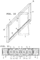
- springs 30 are provided for this purpose, which are inserted into the cavity 9 at the ends of the mounting rails 4 and press the bearing bodies 12 against one another in the longitudinal direction 13 of the mounting rails 4, as the sectional illustration in FIG. 11 shows, which shows a horizontal sectional plane through the Line XI-XI in Fig. 10 corresponds.
- the two mounting rails 4 are connected in this embodiment with connecting brackets 31 which engage at the ends of the mounting rails 4 in their cavities 9 to form a mounting frame.
- the template receiving frame 2, of which several are provided, but only one is indicated by dashed lines in FIG. 10 in order to obtain a clear representation, are similar to the embodiment according to FIGS. 1 and 2 via arms 15 which are shown by the Slots 10 protrude into the cavity 9 of the mounting rails 4, connected to the bearing bodies 12.
Landscapes
- Physics & Mathematics (AREA)
- General Physics & Mathematics (AREA)
- Engineering & Computer Science (AREA)
- Theoretical Computer Science (AREA)
- Mutual Connection Of Rods And Tubes (AREA)
- Sheets, Magazines, And Separation Thereof (AREA)
- Electron Beam Exposure (AREA)
- Exposure And Positioning Against Photoresist Photosensitive Materials (AREA)
- Finger-Pressure Massage (AREA)
- Lasers (AREA)
- Toys (AREA)
Applications Claiming Priority (2)
| Application Number | Priority Date | Filing Date | Title |
|---|---|---|---|
| DE9217446U | 1992-12-21 | ||
| DE9217446U DE9217446U1 (de) | 1992-12-21 | 1992-12-21 | Vorlagenhalter |
Publications (2)
| Publication Number | Publication Date |
|---|---|
| EP0604384A1 EP0604384A1 (de) | 1994-06-29 |
| EP0604384B1 true EP0604384B1 (de) | 1996-07-03 |
Family
ID=6887386
Family Applications (1)
| Application Number | Title | Priority Date | Filing Date |
|---|---|---|---|
| EP93890235A Expired - Lifetime EP0604384B1 (de) | 1992-12-21 | 1993-12-07 | Vorlagenhalter |
Country Status (5)
| Country | Link |
|---|---|
| EP (1) | EP0604384B1 (da) |
| AT (1) | ATE140095T1 (da) |
| DE (2) | DE9217446U1 (da) |
| DK (1) | DK0604384T3 (da) |
| ES (1) | ES2090949T3 (da) |
Families Citing this family (4)
| Publication number | Priority date | Publication date | Assignee | Title |
|---|---|---|---|---|
| DE19701255A1 (de) | 1997-01-16 | 1998-07-23 | Hannecke Wolf D Kunststoff | Vorrichtung zur Präsentation flacher oder biegsamer Gegenstände |
| DE19701257A1 (de) * | 1997-01-17 | 1998-07-23 | Hannecke Wolf D Kunststoff | Säulenpräsentationssystem in Modulbauweise zur Schaustellung von Waren oder Prospektmaterial und insbesondere von dünnen Gegenständen |
| AT2445U1 (de) * | 1997-08-01 | 1998-10-27 | Tiedemann Roman | Ständer für plakate und ähnliche informationsträger |
| DE102005058970B3 (de) * | 2005-12-09 | 2007-05-10 | Forschungszentrum für Medizintechnik und Biotechnologie e.V. | Vorrichtung zum schwenkbaren Anordnen von Informationsträgern |
Family Cites Families (4)
| Publication number | Priority date | Publication date | Assignee | Title |
|---|---|---|---|---|
| FR2436455A1 (fr) * | 1978-09-15 | 1980-04-11 | Mollard Pierre | Dispositif d'affichage mobile |
| GB2124475A (en) * | 1982-08-05 | 1984-02-22 | Byam Design And Manufacturing | Display assembly |
| US5139155A (en) * | 1990-09-24 | 1992-08-18 | Laxson Charles E | Hinged panel storage system |
| DE9112321U1 (de) * | 1991-10-02 | 1991-11-21 | Hauff, Karl, 2407 Bad Schwartau | Befestigungsmittel für eine Halteeinheit |
-
1992
- 1992-12-21 DE DE9217446U patent/DE9217446U1/de not_active Expired - Lifetime
-
1993
- 1993-12-07 EP EP93890235A patent/EP0604384B1/de not_active Expired - Lifetime
- 1993-12-07 DE DE59303136T patent/DE59303136D1/de not_active Expired - Fee Related
- 1993-12-07 DK DK93890235.0T patent/DK0604384T3/da active
- 1993-12-07 ES ES93890235T patent/ES2090949T3/es not_active Expired - Lifetime
- 1993-12-07 AT AT93890235T patent/ATE140095T1/de not_active IP Right Cessation
Also Published As
| Publication number | Publication date |
|---|---|
| DE9217446U1 (de) | 1993-02-18 |
| ES2090949T3 (es) | 1996-10-16 |
| EP0604384A1 (de) | 1994-06-29 |
| ATE140095T1 (de) | 1996-07-15 |
| DK0604384T3 (da) | 1996-11-11 |
| DE59303136D1 (de) | 1996-08-08 |
Similar Documents
| Publication | Publication Date | Title |
|---|---|---|
| DE69801034T2 (de) | Gehäuse von der Art Schminkebehälter | |
| DE2609789A1 (de) | Klammer | |
| DE2711337A1 (de) | Kunststoffklammer | |
| EP0134279A1 (de) | Behälter zur Aufbewahrung von Magnetbandkassetten | |
| DE9402464U1 (de) | Streichkissengerät | |
| EP0190608B1 (de) | Fersenhalter | |
| EP0604384A1 (de) | Vorlagenhalter | |
| EP0010260B1 (de) | Schraubzwinge | |
| EP0204257A2 (de) | Heftmechanik für Loseblatt-Ordner | |
| DE2540340C3 (de) | Einhängeeinrichtung für Schnellhefter, Aktenordner o.dgl | |
| DE3226455C1 (de) | Einrichtung zum Austausch von Gegenstaenden,insbesondere Schreibstiften | |
| DE2419976A1 (de) | Lageranordnung fuer eine welle oder achse | |
| DE29915674U1 (de) | Tragetasche | |
| DE10231670A1 (de) | Becherhalterung, besonders für ein Armaturenbrett in einem Fahrzeug | |
| DE3118125C2 (de) | Verriegelungseinrichtung für Liegesitze | |
| DE3206910C2 (de) | Vorrichtung zum Halten und Aufbewahren von Schreib-, Zeichen- oder Malgeräten | |
| DE3119781C2 (de) | Kopfstütze | |
| DE2608292B2 (de) | Fenstergriffbeschlag mit drehbarer länglicher Abdeckplatte | |
| DE3913319A1 (de) | Moebelscharnier | |
| DE2854453C2 (de) | Skiträger für Kraftfahrzeuge | |
| AT4995U1 (de) | Verbindungselement für trennwände zur facheinteilung einer schublade | |
| DE8800283U1 (de) | Vorrichtung zum Verbinden eines Schuhes mit einem Pedalkörper eines Fahrrades | |
| DE3117118A1 (de) | Scharnier, insbesondere fuer tueren, wie tueren von sicherungs- oder schaltkaesten | |
| DE29505277U1 (de) | Aktenordner | |
| DE2922395A1 (de) | Laufrolle fuer kleinmoebel |
Legal Events
| Date | Code | Title | Description |
|---|---|---|---|
| PUAI | Public reference made under article 153(3) epc to a published international application that has entered the european phase |
Free format text: ORIGINAL CODE: 0009012 |
|
| AK | Designated contracting states |
Kind code of ref document: A1 Designated state(s): AT BE DE DK ES FR GB IT NL SE |
|
| 17P | Request for examination filed |
Effective date: 19941223 |
|
| GRAG | Despatch of communication of intention to grant |
Free format text: ORIGINAL CODE: EPIDOS AGRA |
|
| GRAH | Despatch of communication of intention to grant a patent |
Free format text: ORIGINAL CODE: EPIDOS IGRA |
|
| 17Q | First examination report despatched |
Effective date: 19960305 |
|
| GRAH | Despatch of communication of intention to grant a patent |
Free format text: ORIGINAL CODE: EPIDOS IGRA |
|
| GRAA | (expected) grant |
Free format text: ORIGINAL CODE: 0009210 |
|
| AK | Designated contracting states |
Kind code of ref document: B1 Designated state(s): AT BE DE DK ES FR GB IT NL SE |
|
| REF | Corresponds to: |
Ref document number: 140095 Country of ref document: AT Date of ref document: 19960715 Kind code of ref document: T |
|
| REF | Corresponds to: |
Ref document number: 59303136 Country of ref document: DE Date of ref document: 19960808 |
|
| ITF | It: translation for a ep patent filed | ||
| ET | Fr: translation filed | ||
| REG | Reference to a national code |
Ref country code: ES Ref legal event code: FG2A Ref document number: 2090949 Country of ref document: ES Kind code of ref document: T3 |
|
| GBT | Gb: translation of ep patent filed (gb section 77(6)(a)/1977) |
Effective date: 19961003 |
|
| REG | Reference to a national code |
Ref country code: DK Ref legal event code: T3 |
|
| REG | Reference to a national code |
Ref country code: ES Ref legal event code: FG2A Ref document number: 2090949 Country of ref document: ES Kind code of ref document: T3 |
|
| PLBE | No opposition filed within time limit |
Free format text: ORIGINAL CODE: 0009261 |
|
| STAA | Information on the status of an ep patent application or granted ep patent |
Free format text: STATUS: NO OPPOSITION FILED WITHIN TIME LIMIT |
|
| 26N | No opposition filed | ||
| PGFP | Annual fee paid to national office [announced via postgrant information from national office to epo] |
Ref country code: BE Payment date: 19981008 Year of fee payment: 6 |
|
| PGFP | Annual fee paid to national office [announced via postgrant information from national office to epo] |
Ref country code: GB Payment date: 19981023 Year of fee payment: 6 |
|
| PGFP | Annual fee paid to national office [announced via postgrant information from national office to epo] |
Ref country code: ES Payment date: 19981201 Year of fee payment: 6 |
|
| PGFP | Annual fee paid to national office [announced via postgrant information from national office to epo] |
Ref country code: DK Payment date: 19981222 Year of fee payment: 6 |
|
| PG25 | Lapsed in a contracting state [announced via postgrant information from national office to epo] |
Ref country code: GB Free format text: LAPSE BECAUSE OF NON-PAYMENT OF DUE FEES Effective date: 19991207 Ref country code: DK Free format text: LAPSE BECAUSE OF NON-PAYMENT OF DUE FEES Effective date: 19991207 |
|
| PG25 | Lapsed in a contracting state [announced via postgrant information from national office to epo] |
Ref country code: BE Free format text: LAPSE BECAUSE OF NON-PAYMENT OF DUE FEES Effective date: 19991231 |
|
| BERE | Be: lapsed |
Owner name: TIEDEMANN ROMAN Effective date: 19991231 |
|
| GBPC | Gb: european patent ceased through non-payment of renewal fee |
Effective date: 19991207 |
|
| REG | Reference to a national code |
Ref country code: DK Ref legal event code: EBP |
|
| NLS | Nl: assignments of ep-patents |
Owner name: METO INTERNATIONAL GMBH;METO GMBH |
|
| REG | Reference to a national code |
Ref country code: FR Ref legal event code: TP |
|
| PG25 | Lapsed in a contracting state [announced via postgrant information from national office to epo] |
Ref country code: ES Free format text: LAPSE BECAUSE OF NON-PAYMENT OF DUE FEES Effective date: 20001208 |
|
| PGFP | Annual fee paid to national office [announced via postgrant information from national office to epo] |
Ref country code: FR Payment date: 20040210 Year of fee payment: 11 |
|
| PGFP | Annual fee paid to national office [announced via postgrant information from national office to epo] |
Ref country code: AT Payment date: 20040211 Year of fee payment: 11 |
|
| PGFP | Annual fee paid to national office [announced via postgrant information from national office to epo] |
Ref country code: DE Payment date: 20040212 Year of fee payment: 11 |
|
| PGFP | Annual fee paid to national office [announced via postgrant information from national office to epo] |
Ref country code: NL Payment date: 20040225 Year of fee payment: 11 |
|
| PGFP | Annual fee paid to national office [announced via postgrant information from national office to epo] |
Ref country code: SE Payment date: 20040226 Year of fee payment: 11 |
|
| REG | Reference to a national code |
Ref country code: ES Ref legal event code: FD2A Effective date: 20010113 |
|
| PG25 | Lapsed in a contracting state [announced via postgrant information from national office to epo] |
Ref country code: AT Free format text: LAPSE BECAUSE OF NON-PAYMENT OF DUE FEES Effective date: 20041207 |
|
| PG25 | Lapsed in a contracting state [announced via postgrant information from national office to epo] |
Ref country code: SE Free format text: LAPSE BECAUSE OF NON-PAYMENT OF DUE FEES Effective date: 20041208 |
|
| PG25 | Lapsed in a contracting state [announced via postgrant information from national office to epo] |
Ref country code: NL Free format text: LAPSE BECAUSE OF NON-PAYMENT OF DUE FEES Effective date: 20050701 Ref country code: DE Free format text: LAPSE BECAUSE OF NON-PAYMENT OF DUE FEES Effective date: 20050701 |
|
| EUG | Se: european patent has lapsed | ||
| PG25 | Lapsed in a contracting state [announced via postgrant information from national office to epo] |
Ref country code: FR Free format text: LAPSE BECAUSE OF NON-PAYMENT OF DUE FEES Effective date: 20050831 |
|
| NLV4 | Nl: lapsed or anulled due to non-payment of the annual fee |
Effective date: 20050701 |
|
| REG | Reference to a national code |
Ref country code: FR Ref legal event code: ST |
|
| PG25 | Lapsed in a contracting state [announced via postgrant information from national office to epo] |
Ref country code: IT Free format text: LAPSE BECAUSE OF NON-PAYMENT OF DUE FEES;WARNING: LAPSES OF ITALIAN PATENTS WITH EFFECTIVE DATE BEFORE 2007 MAY HAVE OCCURRED AT ANY TIME BEFORE 2007. THE CORRECT EFFECTIVE DATE MAY BE DIFFERENT FROM THE ONE RECORDED. Effective date: 20051207 |