EP0604399B1 - Y-förmiges Verbindungsstück für Beatmungsgerät - Google Patents
Y-förmiges Verbindungsstück für Beatmungsgerät Download PDFInfo
- Publication number
- EP0604399B1 EP0604399B1 EP94102959A EP94102959A EP0604399B1 EP 0604399 B1 EP0604399 B1 EP 0604399B1 EP 94102959 A EP94102959 A EP 94102959A EP 94102959 A EP94102959 A EP 94102959A EP 0604399 B1 EP0604399 B1 EP 0604399B1
- Authority
- EP
- European Patent Office
- Prior art keywords
- piece
- patient
- sample withdrawal
- tube
- bacteria filter
- Prior art date
- Legal status (The legal status is an assumption and is not a legal conclusion. Google has not performed a legal analysis and makes no representation as to the accuracy of the status listed.)
- Expired - Lifetime
Links
Images


Classifications
-
- A—HUMAN NECESSITIES
- A61—MEDICAL OR VETERINARY SCIENCE; HYGIENE
- A61M—DEVICES FOR INTRODUCING MEDIA INTO, OR ONTO, THE BODY; DEVICES FOR TRANSDUCING BODY MEDIA OR FOR TAKING MEDIA FROM THE BODY; DEVICES FOR PRODUCING OR ENDING SLEEP OR STUPOR
- A61M16/00—Devices for influencing the respiratory system of patients by gas treatment, e.g. ventilators; Tracheal tubes
- A61M16/10—Preparation of respiratory gases or vapours
- A61M16/105—Filters
- A61M16/1055—Filters bacterial
-
- A—HUMAN NECESSITIES
- A61—MEDICAL OR VETERINARY SCIENCE; HYGIENE
- A61M—DEVICES FOR INTRODUCING MEDIA INTO, OR ONTO, THE BODY; DEVICES FOR TRANSDUCING BODY MEDIA OR FOR TAKING MEDIA FROM THE BODY; DEVICES FOR PRODUCING OR ENDING SLEEP OR STUPOR
- A61M16/00—Devices for influencing the respiratory system of patients by gas treatment, e.g. ventilators; Tracheal tubes
- A61M16/08—Bellows; Connecting tubes ; Water traps; Patient circuits
- A61M16/0816—Joints or connectors
- A61M16/0833—T- or Y-type connectors, e.g. Y-piece
-
- A—HUMAN NECESSITIES
- A61—MEDICAL OR VETERINARY SCIENCE; HYGIENE
- A61M—DEVICES FOR INTRODUCING MEDIA INTO, OR ONTO, THE BODY; DEVICES FOR TRANSDUCING BODY MEDIA OR FOR TAKING MEDIA FROM THE BODY; DEVICES FOR PRODUCING OR ENDING SLEEP OR STUPOR
- A61M16/00—Devices for influencing the respiratory system of patients by gas treatment, e.g. ventilators; Tracheal tubes
- A61M16/08—Bellows; Connecting tubes ; Water traps; Patient circuits
- A61M16/0816—Joints or connectors
- A61M16/0841—Joints or connectors for sampling
- A61M16/085—Gas sampling
-
- A—HUMAN NECESSITIES
- A61—MEDICAL OR VETERINARY SCIENCE; HYGIENE
- A61M—DEVICES FOR INTRODUCING MEDIA INTO, OR ONTO, THE BODY; DEVICES FOR TRANSDUCING BODY MEDIA OR FOR TAKING MEDIA FROM THE BODY; DEVICES FOR PRODUCING OR ENDING SLEEP OR STUPOR
- A61M16/00—Devices for influencing the respiratory system of patients by gas treatment, e.g. ventilators; Tracheal tubes
- A61M16/10—Preparation of respiratory gases or vapours
- A61M16/105—Filters
- A61M16/106—Filters in a path
Definitions
- the present invention relates to a connection arrangement for connecting a patient to a respirator, anaesthesia machine or similar, of the type mentioned in the preamble of claim 12 and a Y-piece for the type mentioned in the preamble of claim 1 for use in such a connection arrangement.
- Y-piece also includes shapes other than a conventional "Y". Of importance is only that said patient attachment piece is able to be connected to an inhalation resp an exhalation tube.
- the expression “Y-piece” also includes for example T-connections and even connections for connecting coaxially arranged inhalation and exhalation tubes.
- a Y-piece with a sample withdrawal outlet extending perpendicular to the flow of the air in the Y-piece is known from US-A 4 558 708 which is used as a basis for the preambles of claims 1 and 12, respectively.
- the patient attachment piece can by way of example be designed in accordance with US-A-4 516 573.
- a bellowed patient attachment piece which contains a wad of moisture and heat absorbing material. In this way heat and moisture is taken up from the exhaled gas and given to the inhaled gas.
- Such patient attachment pieces are often connected with various types of Y-pieces and are possibly also equipped with various types of bacteria filters. The more components which are connected leads to a bulkier construction which can be inconvenient for the patient. Furthermore, the connection of a plurality of components leads to the risk of, on the one hand, leakage and, on the other hand, incorrectly connected components.
- WO-A-8904864 describes a sample withdrawal tube which samples exhaled air after it has passed through a bacteria filter in a regenerative heat and moisture exchanger.
- the withdrawal tube samples air which can contain unfiltered inhalation air from the dead volume of the exchanger as well as filtered exhalation air from the patient.
- a Y-piece for use in a connection arrangement for connecting a patient to a respirator, anaesthesia machine or similar
- said Y-piece comprises a sample withdrawal outlet wherein a bacteria filter is mounted in said Y-piece substantially perpendicular to the through-flow direction, and the sample withdrawal outlet is arranged in the exhalation flow direction after the bacteria filter and is connected to a sample withdrawal tube which extends from the bacteria filter to the outlet and is arranged so as to take bacteria-free samples through said filter.
- the present invention also relates to connection arrangement for connecting a patient to a respirator, anaesthesia machine or similar, comprising a patient attachment piece, a Y-piece, arranged to join the patient attachment piece to an inhalation resp exhalation tube, wherein the Y-piece is a Y-piece of the type described above.
- connection arrangement for connecting a patient to a respirator, anaesthesia machine or similar, comprising a patient attachment piece, a Y-piece, arranged to join the patient attachment piece to an inhalation resp exhalation tube, wherein the Y-piece is a Y-piece of the type described above.
- the bacteria filter is arranged within the Y-piece itself.
- the first sample withdrawal tube can via the bacteria filter be connected to a second sample withdrawal tube which extends from the filter towards the patient attachment piece and preferably up to and, possibly into this piece.
- the filtering of the withdrawn samples is hereby simplified, if the said first and second sample withdrawal tubes are arranged on either side of the bacteria filter and are in pressurized contact therewith via a at right angles to the flow direction widened portion, for example a cone-shaped and/or cylindrical funnel-like portion.
- the moisture content of the withdrawn sample is reduced, if the patient attachment piece contains a heat and moisture exchange system in the form of a wad or similar of a flexible material, such as fibres, with the ability to take heat and moisture from exhaled gas and subsequently deliver this to the inhaled gas.
- a heat and moisture exchange system is disclosed in US-A-4 516 573.
- the through-flow area of the Y-piece can hereby be enlarged in comparison with that of the patient attachment piece.
- a simple construction with a view to manufacturing is achieved if the Y-piece is formed from two bowl-shaped parts and the bacteria filter is clamped between these parts substanially perpendicular to the through-flow direction.
- the Y-piece of the connection arrangement normally includes three attachment nipples, namely one for the patient attachment piece, one for the inhalation tube and one for the exhalation tube. From a manufacturing point of view a particularly suitable construction is obtained when these nipples are arranged substanially parallel to each other.
- the Y-piece's through-flow area is maximized in proportion to its volume through a substanially circular form, whilst its length in the flow direction is restricted to that which the function allows.
- the sample withdrawal outlet is suitably arranged in the form of a nipple substanially in the middle of a Y-piece with, in a direction perpendicular to the through-flow direction, a somewhat drawn out through-flow area, for example substanially oval or rounded-rectangular shaped, between the attachment nipples for the inhalation resp exhalation tubes and preferably parallel to these nipples.
- the sample withdrawal outlet can have the form of a nipple which is angled in respect to the other nipples. Important in both cases is, however, that it is shieldably arranged between the attachment nipples for the inhalation resp exhalation tubes.
- the Y-piece requires a certain minimum volume.
- the included attachment nipples should have a certain standard dimension.
- the sample withdrawal outlet is connected to the first sample withdrawal tube which extends from the outlet to the bacteria filter.
- This sample withdrawal tube can, as mentioned above, via the bacteria filter, be connected to a second sample withdrawal tube which extends from the filter towards the patient attachment piece and preferably up to and, possibly, into this piece. In this way the effect of the Y-piece's inner volume on the withdrawal sample is substantially eliminated.
- the sample withdrawal is further simplified when said first and second sample withdrawal tubes are arranged on either side of the bacteria filter and are in pressured contact therewith via an at right angles to the flow direction widened portion, for example a cone-shaped and/or cylindrical funnel-like portion.
- the simplification of, amongst other things, the flow of the sample through the bacteria filter is achieved, whilst leakage is prevented between the inner sample withdrawal tube and the atmosphere surrounding it.
- one or both bowl-shaped halves of the Y-piece can be provided with support webs for one or both tubes.
- connection arrangement serve at the same time as a heat and moisture exchanger by being equipped with a wad, or similar, of the above-mentioned type, then this should suitably be impregnated with an antibacterial agent, for example chlorhexidine or hydrogen peroxide, and/or with a hygroscopic substance, such as magnesium chloride, lithium chloride or calcium chloride.
- an antibacterial agent for example chlorhexidine or hydrogen peroxide
- a hygroscopic substance such as magnesium chloride, lithium chloride or calcium chloride.
- the above-mentioned wad or similar consists of fibres of a plastic material having a certain melting point, such as polypropylene, which are coated with another plastic material having a lower melting point, such as polyethylene, with the aid of which the fibres are bounded by heating to said lower melting point.
- a plastic material having a certain melting point such as polypropylene
- another plastic material having a lower melting point such as polyethylene
- At least one part of the patient attachment piece is made from transparent material.
- This part which preferably is located nearest the patient, is left free from other material in order to serve as a secretion trap and/or inspection zone.
- the patient attachment piece is not required. This is therefore suitably arranged to be disconnectable from the Y-piece.
- Said sample withdrawal outlet is appropriately arranged in a dome, or similar, directed towards the interior of the Y-piece and which is arranged to stabilize the outlet whilst also reducing the inner volume of the Y-piece.
- both bowl-shaped parts of the Y-piece are provided with internal stiffening webs which are so arranged that they disturb the through-flow as little as possible, for example by being radially directed in relation to the principal through-flow direction, whilst also being arranged to support the bacteria filter on both sides.
- Figure 1 shows a section through a Y-piece according to the invention.
- Figure 2 shows the same Y-piece as in Figure 1, but from above.
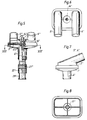
- Figure 3 shows a somewhat modified Y-piece.
- Figure 4 shows the last-mentioned Y-piece seen from underneath.
- FIG. 5 shows schematically a somewhat more complete connection arrangement according to the invention.
- Figure 6 shows a plan view of the connection arrangement according to Figure 5.
- Figure 7 shows a section through a nipple and a side view of another nipple belonging to the Y-piece which is included in the connection arrangement according to Figure 5.
- Figure 8 shows a section along line VIII-VIII in Figure 5, but without the filter.
- Figures 9-12 show views corresponding to Figures 5-8 of a modified embodiment of the connection arrangement according to the invention.
- Figure 13 shows a further embodiment of a Y-piece. At the same time fig 13a shows, on a larger scale, a part of fig 13.
- Figure 14 shows the Y-piece according to Figure 13 seen from beneath and Figure 15 shows the same seen from above.
- Figures 1 and 2 show a section resp end view of a Y-piece according to the invention which is intended to be included in a connection arrangement also according to the invention.
- This Y-piece comprises two bowl-shaped parts 1 and 2 with a bacteria filter 3 clamped therebetween.
- the upper bowl-shaped part 1 is provided with a nipple 4 which is intended to be connected to a patient attachment piece.
- the lower bowl-shaped part 2 is provided with two parallel nipples 5 and 6 which are intended to be connected to an inhalation tube resp an exhalation tube, which in turn are intended to be connected to a respirator, anaesthesia machine or similar.
- the bacteria filter 3 is clamped between a circular ridge 7 on the upper bowl-shaped part 3 and a circular groove 8 in the lower bowl-shaped part 2.
- This groove 8 is formed from an outer flange 9 and an inner ridge 10.
- the flange 9 is terminated at its outer portion by a radially extending partial flange 11 which is intended to be fixed to the upper bowl-shaped part 1 by, for example, glueing or welding , preferably ultrasonic welding.
- the concentricity of the two bowl-shaped parts 1 and 2 is hereby facilitated by an outer peripheral flange 12 on the upper bowl-shaped part 1.
- the lower bowl-shaped part 2 further comprises a sample withdrawal outlet in the form of a nipple 14, which is preferably provided with an inner or outer screw thread or other fixing means 15.
- the nipple 14 is connected to a first sample withdrawal tube 16 which in turn, via filter 3, is connected to a second sample withdrawal tube 17.
- Both the sample withdrawal tubes and the filter 3 are supported by radially extending support webs 18 resp 19.
- the sample withdrawal tube 17 is terminated inside with a widened cylindrical portion 20 which via the filter presses against a corresponding portion of the sample withdrawal tube 16. As is evident from Figure 2, the sample withdrawal tube 17 is located between four radially directed support webs 19.
- FIGs 3 and 4 there is shown a modified embodiment of a Y-piece in the connection arrangement according to the invention.
- the construction corresponds in principle with that according to Figure 1 and 2.
- the same reference numerals have been used but with the addition of a dash.
- the most significant difference is that the attachment nipples 5' resp 6' are angularly formed.
- the sample withdrawal tubes 16' and 17' have been given a somewhat different shape.
- FIGS 5-8 there is shown a somewhat more complete realization of an embodiment of the connection arrangement according to the invention. This also principally corresponds with that which has been described above. Thus the same figure reference numerals are used for corresponding details, but with the addition of a double dash.
- Reference numerals 5'' resp 6'' thus denotes two nipples which are intended to be attached to an inhalation tube resp an exhalation tube.
- the bacteria filter itself is denoted by 3''.
- Reference numeral 14'' denotes a sample withdrawal nipple which is connected to a first sample withdrawal tube 16''. The latter is in turn via the filter 3'' in contact with a second sample withdrawal tube 17''.
- Reference numeral 4'' denotes a nipple with the aid of which the Y-piece is connected to a patient attachment piece 21''. This is preferably designed substanially in accordance with that described in US-A-4 516 573. It is, however, preferably of uniform thickness. Within the patient attachment piece there is preferably a wad or similar 22'' of a moisture and heat absorbing material which serves to take up heat and moisture from the exhaled gas and pass this to the inhaled gas. Finally in Figure 5, reference numeral 23'' denotes an attachment pipe or cone with the help of which the patient attachment piece 21'' can be connected to a tracheal tube or similar.
- the Y-piece shown in Figures 5-8 also consists of two bowl-shaped parts 1'' resp 2'' but differs from the above described Y-pieces in that, for example these parts have been given a rounded rectangular shape. Furthermore the attachment nipples 5'' and 6'' are arranged at a different angle to that which is shown in, for example, Figure 3 and 4. Finally, reference numerals 25'' denotes a dome directed towards the interior of the Y-piece in which the sample withdrawal nipple 14'' is arranged. Thanks to this arrangement the Y-piece's inner volume is reduced whilst the sample withdrawal tube 16'' is stabilized.
- the construction according to Figures 9-12 substantially corresponds with that according to Figures 5-8. Corresponding details have thus been given the same figure reference numerals, but with the suffix a instead of the double dashes used in Figures 5-8.
- the construction according to Figures 9-12 differs from that according to Figures 5-8 in that the nipples 5a and 6a are arranged parallel to the nipple 4a. Furthermore the fibre wad 22a does not fill the whole patient attachment piece 21a. A free space 24a is left nearest the patient, which is intended to serve as a secretion trap and which can also serve as an inspection zone if the patient attachment piece is made from a transparent material.
- reference numeral 25a denotes a dome directed towards the interior of the Y-piece in which the sample withdrawal nipple 14a is arranged. Thanks to this arrangement the Y-piece's inner volume is reduced whilst the sample withdrawal tube 16a is stabilized.
- FIGS 13-15 are showing a further alternative for the Y-piece made in accordance with the invention.
- This embodiment corresponds essentially to the one shown in Figures 1 and 2.
- Different reference numerals have, however, been used, but all with the addition of a'.
- the Y-piece described comprises two bowl-shaped parts 5a' and 6a' with a bacteria filter 7a' clamped therebetween.
- the upper bowl-shaped part 5a' is provided with a nipple 1a', which is intended to be connected to a patient attachment piece.
- the lower bowl-shaped part 6a' is provided with two parallel nipples 2a' and 3a' which are intended to be connected to an inhalation tube resp exhalation tube, which in turn are intended to be connected to a respirator, anaesthesia machine or similar.
- the bacteria filter 7a' is clamped in the same way as the filter 3 in fig 1.
- the lower bowl-shaped part 6a' further comprises a sample withdrawal outlet in the form of a nipple 11a'.
- the nipple 11a' is connected to a first sample withdrawal tube 12a' which in turn, via the filter 7a', is connected to a second sample withdrawal tube 13a'.
- the main difference between the embodiment according to Figures 1-2 and the one according to Figures 13-15 is that the last mentioned embodiment is provided with a partition wall 4a', preferably made in one piece with the two sample withdrawal tubes 12a' and 13a', separating exhaled gas from inhaled gas. As shown in Figure 15 the part 5a' may also be provided with a support wall 10a' intended to support the filter 7a'.
Landscapes
- Health & Medical Sciences (AREA)
- Life Sciences & Earth Sciences (AREA)
- Public Health (AREA)
- Engineering & Computer Science (AREA)
- Anesthesiology (AREA)
- Biomedical Technology (AREA)
- Heart & Thoracic Surgery (AREA)
- Pulmonology (AREA)
- Animal Behavior & Ethology (AREA)
- Hematology (AREA)
- General Health & Medical Sciences (AREA)
- Emergency Medicine (AREA)
- Veterinary Medicine (AREA)
- Sampling And Sample Adjustment (AREA)
- Investigating Or Analysing Biological Materials (AREA)
- Respiratory Apparatuses And Protective Means (AREA)
Claims (16)
- Y-Stück zur Verwendung in einer Verbindungsanordnung zum Verbinden eines Patienten mit einem Beatmungsgerät, einer Narkosemaschine oder ähnlichem, bei dem das Y-Stück einen Probenabführungsauslaß (14) aufweist, dadurch gekennzeichnet, daß ein Bakterienfilter (3) in dem Y-Stück im wesentlichen rechtwinklig zu der Durchströmungsrichtung angebracht ist, und daß der Probenabführungsauslaß (14) in der Ausatmungsströmungsrichtung hinter dem Bakterienfilter (3) angeordnet und mit einer ersten Probenabführungsröhre (16) verbunden ist, die sich von dem Bakterienfilter (3) zu dem Auslaß (14) erstreckt und derart angeordnet ist, daß sie bakterienfreie Proben über das Filter (3) aufnimmt.
- Y-Stück nach Anspruch 1, dadurch gekennzeichnet, daß die erste Probenabführungsröhre (16) über das Bakterienfilter (3) mit einer zweiten Probenabführungsröhre (17) verbunden ist, die sich von dem Bakterienfilter (3) bis zu einer Düse (4, 4', 4'', 4a), die mit einem Patientenverbindungsteil (21''; 21 a) verbindbar ist und die sich vorzugsweise durch diese Düse (4) hindurch und möglicherweise bis in dieses Teil erstreckt.
- Y-Stück nach Anspruch 2, dadurch gekennzeichnet, daß die erste und die zweite Probenabführungsröhre (16, 17) jeweils auf einer Seite des Bakterienfilters (3) angeordnet sind und mit diesem über einen rechtwinklig zu der Strömungsrichtung verbreiterten Abschnitt, beispielsweise einen kegelförmigen und/oder einen trichterförmigen Abschnitt (20), in Druckberührung stehen.
- Y-Stück nach einem der vorhergehenden Ansprüche, dadurch gekennzeichnet, daß das Y-Stück mit einer Trennwand (4a') versehen ist, die das ausgeatmete Gas von dem eingeatmeten Gas trennt und sich in der Richtung zu dem Patienten bis mindestens zu dem Bakterienfilter (7a') erstreckt.
- Y-Stück nach den Ansprüchen 2 bis 4, dadurch gekennzeichnet, daß die Durchströmungsfläche des Y-Stücks (1, 2) im Vergleich mit derjenigen des verbindbaren Patientenverbindungsteils vergrößert ist.
- Y-Stück nach einem der vorhergehenden Ansprüche, bei dem das Y-Stück (1, 2) drei Anbringungsnippel aufweist, nämlich einen (4) für das Patientenverbindungsteil, einen (5) für den Inhalationsschlauch und einen (6) für den Ausatmungsschlauch, dadurch gekennzeichnet, daß die Nippel (4 bis 6) im wesentlichen parallel zueinander angeordnet sind.
- Y-Stück nach einem der vorhergehenden Ansprüche, dadurch gekennzeichnet, daß die Durchströmungsfläche des Y-Stücks (1, 2) in Relation zu seinem Volumen aufgrund einer im wesentlichen kreisförmigen Form maximiert ist, wohingegen seine Länge in der Strömungsrichtung auf diejenige Länge, die die Funktion ermöglicht, beschränkt ist.
- Y-Stück nach Anspruch 6, dadurch gekennzeichnet, daß der Probenabführungsauslaß (14'' oder 14a) vorzugsweise in der Form eines Nippels im wesentlichen in der Mitte des Y-Stücks (1'', 2''; 1a, 2a) zwischen den Anbringungsnippeln (5'', 6''; 5a, 6a) für den Inhalationsschlauch bzw. den Ausatmungsschlauch sowie vorzugsweise parallel zu diesen Nippeln angeordnet ist, so daß der Probenabführungsauslaß (14'', 14a) in der rechtwinklig zu seiner Durchströmungsrichtung verlaufenden Richtung eine etwas herausgezogene Durchströmungsfläche, beispielsweise eine im wesentlichen ovale oder mit abgerundeten Ecken versehene rechteckförmige Durchströmungsfläche aufweist.
- Y-Stück nach einem der vorhergehenden Ansprüche, dadurch gekennzeichnet, daß das Y-Stück zwei schalenförmige Hälften (1, 2) aufweist, wobei eine oder beide dieser schalenförmigen Hälften (1, 2) mit Stützstegen (18, 19) für die erste und/oder die zweite Probenabführungsröhre versehen sind.
- Y-Stück nach Anspruch 9, dadurch gekennzeichnet, daß der Probenabfühtungsauslaß (14'', 14a) in einem Dom oder ähnlichem angeordnet ist, der in Richtung zu dem Inneren des Y-Stücks (1, 2) gerichtet ist, und der derart angeordnet ist, daß er den Auslaß stabilisiert, wobei er zugleich auch das Innenvolumen des Y-Stücks verringert.
- Y-Stück nach einem der Ansprüche 9 oder 10, dadurch gekennzeichnet, daß die beiden schalenförmigen Teile des Y-Stücks (1, 2) mit Stützstegen (18, 19) versehen sind, die derart angeordnet sind, daß sie die Durchströmung so wenig wie möglich stören. indem sie beispielsweise mit Bezug zu der hauptsächlichen Strömungsrichtung radial ausgerichtet sind, wobei sie ferner derart angeordnet sind, daß sie das Bakterienfilter (3) an dessen beiden Seiten halten.
- Verbindungsanordnung zur Verbindung eines Patienten mit einem Beatmungsgerät, einer Narkosemaschine oder ähnlichem, mit einem Patientenverbindungsteil (21'' oder 21a) und einem sogenannten Y-Stück (1, 2), das derart angeordnet ist, daß es das Patientenverbindungsteil mit einem Inhalationsschlauch bzw. Ausatmungsschlauch verbindet, dadurch gekennzeichnet, daß das Y-Stück ein Y-Stück gemäß einem der vorhergehenden Ansprüche ist.
- Verbindungsanordnung nach Anspruch 12, dadurch gekennzeichnet, daß das Patientenverbindungsteil (21'' oder 21a) flexibel ist und ein Wärme- und Dampfaustauschsystem in der Form eines Bündels oder ähnlichem (22'' oder 22a) aus einem flexiblen Material, wie etwa aus Fasern, enthält, das die Fähigkeit besitzt, Wärme und Feuchtigkeit aus dem ausgeatmeten Gas aufzunehmen und diese nachfolgend zu dem inhalierten Gas zu leiten, wobei das Bündel oder dergleichen (22'', 22a) mit einem antibakteriellen Mittel, z. B. Chlorhexidin oder Wasserstoffperoxid, und/oder mit einer hygroskopischen Substanz, wie etwa Magnesiumchlorid, Lithiumchlorid oder Kalziumchlorid imprägniert ist.
- Verbindungsanordnung nach Anspruch 13, dadurch gekennzeichnet, daß das Bündel oder ähnliches (22'', 22a) aus Fasern aus einem Kunststoffmaterial mit einem gewissen Schmelzpunkt, wie etwa aus Polypropylen besteht, die mit einem weiteren Kunststoffmaterial beschichtet sind, das einen niedrigeren Schmelzpunkt aufweist, wie etwa mit Polyethylen, mit dessen Hilfe die Fasern dadurch miteinander verbunden werden, daß sie auf den niedrigeren Schmelzpunkt erwärmt werden.
- Verbindungsanordnung nach einem der Ansprüche 12 bis 14, dadurch gekennzeichnet, daß mindestens ein Teil (24a) des Patientenverbindungsteils (21a) transparent ist und sich in diesem Teil kein weiteres Material, vorzugsweise so nahe wie möglich bei dem Patienten, befindet, so daß es als Sekretfalle und/oder als Inspektionszone dienen kann.
- Verbindungsanordnung nach einem der Ansprüche 12 bis 15, dadurch gekennzeichnet, daß das Patientenverbindungsteil (z. B. 21'' oder 21a) von dem Y-Stück (1,2) abtrennbar ist.
Applications Claiming Priority (5)
| Application Number | Priority Date | Filing Date | Title |
|---|---|---|---|
| SE9002162A SE508129C2 (sv) | 1990-06-18 | 1990-06-18 | Kopplingsanordning avsedd för sammankoppling av en patient med en ventilator |
| SE9002162 | 1990-06-18 | ||
| SE9003505A SE507108C2 (sv) | 1990-11-02 | 1990-11-02 | Kopplingsanordning för sammankoppling av en patient med en ventilator, narkosapparat eller dylikt |
| SE9003505 | 1990-11-02 | ||
| EP91108316A EP0462412B1 (de) | 1990-06-18 | 1991-05-23 | Y-förmiges Verbindungsstück für Beatmungsgerät |
Related Parent Applications (3)
| Application Number | Title | Priority Date | Filing Date |
|---|---|---|---|
| EP91108316.0 Division | 1991-05-23 | ||
| EP91108316A Division-Into EP0462412B1 (de) | 1990-06-18 | 1991-05-23 | Y-förmiges Verbindungsstück für Beatmungsgerät |
| EP91108316A Division EP0462412B1 (de) | 1990-06-18 | 1991-05-23 | Y-förmiges Verbindungsstück für Beatmungsgerät |
Publications (2)
| Publication Number | Publication Date |
|---|---|
| EP0604399A1 EP0604399A1 (de) | 1994-06-29 |
| EP0604399B1 true EP0604399B1 (de) | 1998-12-02 |
Family
ID=26660802
Family Applications (2)
| Application Number | Title | Priority Date | Filing Date |
|---|---|---|---|
| EP94102959A Expired - Lifetime EP0604399B1 (de) | 1990-06-18 | 1991-05-23 | Y-förmiges Verbindungsstück für Beatmungsgerät |
| EP91108316A Expired - Lifetime EP0462412B1 (de) | 1990-06-18 | 1991-05-23 | Y-förmiges Verbindungsstück für Beatmungsgerät |
Family Applications After (1)
| Application Number | Title | Priority Date | Filing Date |
|---|---|---|---|
| EP91108316A Expired - Lifetime EP0462412B1 (de) | 1990-06-18 | 1991-05-23 | Y-förmiges Verbindungsstück für Beatmungsgerät |
Country Status (5)
| Country | Link |
|---|---|
| EP (2) | EP0604399B1 (de) |
| JP (1) | JPH0686816A (de) |
| DE (2) | DE69130577T2 (de) |
| DK (2) | DK0604399T3 (de) |
| ES (2) | ES2089054T3 (de) |
Cited By (4)
| Publication number | Priority date | Publication date | Assignee | Title |
|---|---|---|---|---|
| US8839791B2 (en) | 2011-06-22 | 2014-09-23 | Breathe Technologies, Inc. | Ventilation mask with integrated piloted exhalation valve |
| US9038634B2 (en) | 2011-06-22 | 2015-05-26 | Breathe Technologies, Inc. | Ventilation mask with integrated piloted exhalation valve |
| US9486602B2 (en) | 2011-06-22 | 2016-11-08 | Breathe Technologies, Inc. | Ventilation mask with integrated piloted exhalation valve and method of ventilating a patient using the same |
| US9878121B2 (en) | 2013-03-13 | 2018-01-30 | Breathe Technologies, Inc. | Ventilation mask with heat and moisture exchange device |
Families Citing this family (29)
| Publication number | Priority date | Publication date | Assignee | Title |
|---|---|---|---|---|
| US5307794A (en) * | 1992-04-01 | 1994-05-03 | Sensormedics Corporation | Oscillating ventilator apparatus and method and patient isolation apparatus |
| EP0590289A1 (de) * | 1992-09-28 | 1994-04-06 | Engström Medical Ab | Patientenanschluss |
| EP0700687A1 (de) * | 1994-06-23 | 1996-03-13 | Ralph A. Milliken | T-Stück mit doppeltem Rückschlagventil und mit einem ein Gewinde aufweisenden, weiblichen Luerverbinder für Beatmungsgerät |
| US5505768A (en) * | 1994-10-11 | 1996-04-09 | Altadonna; Anthony J. | Humidity moisture exchanger |
| GB9612656D0 (en) * | 1996-06-18 | 1996-08-21 | Broome Ian J | Anaesthetic filter unit |
| WO1998011931A1 (en) * | 1996-09-19 | 1998-03-26 | Pall Corporation | Breathing filter |
| US6003511A (en) | 1996-11-18 | 1999-12-21 | Medlis Corp. | Respiratory circuit terminal for a unilimb respiratory device |
| US5778872A (en) | 1996-11-18 | 1998-07-14 | Medlis, Inc. | Artificial ventilation system and methods of controlling carbon dioxide rebreathing |
| US6439231B1 (en) | 1996-11-18 | 2002-08-27 | Medlis Corp. | Artificial ventilation systems and components thereof, and methods for providing, assembling and utilizing same |
| GB9701995D0 (en) * | 1997-01-31 | 1997-03-19 | Smiths Industries Plc | Heat and moisture exchangers and systems |
| DE19903732B4 (de) * | 1999-01-30 | 2007-12-13 | Gottlieb Weinmann - Geräte für Medizin und Arbeitsschutz - GmbH + Co KG | Vorrichtung zur Beatmung sowie Verfahren zur Aufbereitung eines Beatmungsgases |
| GB0112264D0 (en) * | 2001-05-19 | 2001-07-11 | Intersurgical Ltd | Inhalation handset |
| US7717109B2 (en) | 2001-09-24 | 2010-05-18 | F-Concepts Llc | Breathing systems with post-inspiratory valve fresh gas flow input, components for implementing same, and methods of use |
| NZ532166A (en) | 2001-09-24 | 2007-01-26 | Atsuo F Fukunaga | Breathing circuits having unconventional respiratory conduits and systems and methods for optimising utilisation of fresh gases |
| US7261105B2 (en) | 2001-09-24 | 2007-08-28 | F-Concepts Llc | Breathing circuits having unconventional respiratory conduits and systems and methods for optimizing utilization of fresh gases |
| US6698424B2 (en) | 2001-12-21 | 2004-03-02 | Kimberly-Clark Worldwide, Inc. | Medical connector for a respiratory assembly |
| GB0412482D0 (en) * | 2004-06-03 | 2004-07-07 | Intersurgical Ltd | Improvements relating to medical respiratory apparatus |
| GB2452442B (en) * | 2005-06-02 | 2009-07-08 | Intersurgical Ag | Improvements relating to Medical Respiratory Apparatus |
| GB2473826B (en) * | 2009-09-23 | 2015-01-07 | Flexicare Medical Ltd | A respiratory device |
| US10143818B2 (en) | 2013-01-22 | 2018-12-04 | Fisher & Paykel Healthcare Limited | Dual-connector wye piece |
| WO2014136019A1 (en) | 2013-03-07 | 2014-09-12 | Koninklijke Philips N.V. | Manifold assembly for respiratory interface device |
| EP3079746A4 (de) * | 2013-12-05 | 2017-07-05 | Pawel Wisniewski | Gefilterte wärme- und feuchtigkeitsaustauschvorrichtung für ein atmungssystem |
| US20170246417A1 (en) | 2014-09-17 | 2017-08-31 | Fisher & Paykel Healthcare Limited | Connectors for respiratory assistance systems |
| DE102015002052A1 (de) | 2015-02-16 | 2016-08-18 | Weinmann Emergency Medical Technology Gmbh + Co. Kg | Filter sowie Vorrichtung zur Beatmung mit Filter |
| WO2017070696A1 (en) | 2015-10-24 | 2017-04-27 | Kings Systems Corporation | Breathing circuit systems and devices |
| CN111050830A (zh) | 2017-06-23 | 2020-04-21 | 费雪派克医疗保健有限公司 | 用于呼吸辅助系统的连接器 |
| DE102017011909B4 (de) * | 2017-12-21 | 2025-02-27 | Dräger Safety AG & Co. KGaA | Maskenadapter für den Anschluss von zwei Atemschläuchen eines Kreislaufatemschutzgerätes an einer Atemmaske |
| JP7260307B2 (ja) * | 2019-01-21 | 2023-04-18 | 日本無機株式会社 | 人工呼吸器、及び人工呼吸システム |
| FR3113604A1 (fr) * | 2020-08-26 | 2022-03-04 | Infiplast | Dispositif de filtration pour circuit respiratoire |
Family Cites Families (8)
| Publication number | Priority date | Publication date | Assignee | Title |
|---|---|---|---|---|
| FR1121482A (fr) * | 1954-08-27 | 1956-08-17 | Appareils pour la respiration artificielle, l'inhalation, l'anesthésie, etc. | |
| DE2529050C2 (de) * | 1975-06-30 | 1983-01-05 | Drägerwerk AG, 2400 Lübeck | Feuchtigkeitsaustauscher in Geräten für Atmung und Narkose |
| SE434703B (sv) * | 1982-02-23 | 1984-08-13 | Gambro Engstrom Ab | Anordning for anslutning av en narkos- eller respiratorapparat till en patient |
| US4456014A (en) * | 1983-01-03 | 1984-06-26 | Thoratec Laboratories Corporation | Flow restrictor |
| US4558708A (en) * | 1984-10-24 | 1985-12-17 | Tri-Med, Inc. | Patient's airway adapter to withdraw a patient's gas samples for testing free of sputum mucus and/or condensed water, by utilizing a hollow cylindrical hydrophobic liquid baffle |
| AU7943387A (en) * | 1986-10-16 | 1988-04-21 | Intertech Resources Inc. | Heat and moisture exchanger for respiratory gases |
| SE459901B (sv) * | 1987-11-25 | 1989-08-21 | Gibeck Respiration Ab | Anordning foer oevervakning av en till en ventilator ansluten patient |
| GB8824865D0 (en) * | 1988-10-24 | 1988-11-30 | Antec Systems | Gas sampling device & water trap |
-
1991
- 1991-05-23 DE DE69130577T patent/DE69130577T2/de not_active Expired - Fee Related
- 1991-05-23 ES ES91108316T patent/ES2089054T3/es not_active Expired - Lifetime
- 1991-05-23 EP EP94102959A patent/EP0604399B1/de not_active Expired - Lifetime
- 1991-05-23 ES ES94102959T patent/ES2127300T3/es not_active Expired - Lifetime
- 1991-05-23 EP EP91108316A patent/EP0462412B1/de not_active Expired - Lifetime
- 1991-05-23 DE DE69120734T patent/DE69120734T2/de not_active Expired - Fee Related
- 1991-05-23 DK DK94102959T patent/DK0604399T3/da active
- 1991-05-23 DK DK91108316.0T patent/DK0462412T3/da active
- 1991-06-17 JP JP3144741A patent/JPH0686816A/ja active Pending
Cited By (8)
| Publication number | Priority date | Publication date | Assignee | Title |
|---|---|---|---|---|
| US8839791B2 (en) | 2011-06-22 | 2014-09-23 | Breathe Technologies, Inc. | Ventilation mask with integrated piloted exhalation valve |
| US8844533B2 (en) | 2011-06-22 | 2014-09-30 | Breathe Technologies, Inc. | Ventilation mask with integrated piloted exhalation valve |
| US9038634B2 (en) | 2011-06-22 | 2015-05-26 | Breathe Technologies, Inc. | Ventilation mask with integrated piloted exhalation valve |
| US9038635B2 (en) | 2011-06-22 | 2015-05-26 | Breathe Technologies, Inc. | Ventilation mask with integrated piloted exhalation valve |
| US9327092B2 (en) | 2011-06-22 | 2016-05-03 | Breathe Technologies, Inc. | Ventilation mask with integrated piloted exhalation valve |
| US9415183B2 (en) | 2011-06-22 | 2016-08-16 | Breathe Technologies, Inc. | Ventilation mask with integrated piloted exhalation valve |
| US9486602B2 (en) | 2011-06-22 | 2016-11-08 | Breathe Technologies, Inc. | Ventilation mask with integrated piloted exhalation valve and method of ventilating a patient using the same |
| US9878121B2 (en) | 2013-03-13 | 2018-01-30 | Breathe Technologies, Inc. | Ventilation mask with heat and moisture exchange device |
Also Published As
| Publication number | Publication date |
|---|---|
| ES2089054T3 (es) | 1996-10-01 |
| DE69130577D1 (de) | 1999-01-14 |
| EP0462412A2 (de) | 1991-12-27 |
| ES2127300T3 (es) | 1999-04-16 |
| DE69120734D1 (de) | 1996-08-14 |
| EP0604399A1 (de) | 1994-06-29 |
| JPH0686816A (ja) | 1994-03-29 |
| EP0462412B1 (de) | 1996-07-10 |
| EP0462412A3 (en) | 1992-02-05 |
| DK0604399T3 (da) | 1999-08-16 |
| DE69120734T2 (de) | 1997-02-13 |
| DE69130577T2 (de) | 2000-07-06 |
| DK0462412T3 (da) | 1996-08-12 |
Similar Documents
| Publication | Publication Date | Title |
|---|---|---|
| EP0604399B1 (de) | Y-förmiges Verbindungsstück für Beatmungsgerät | |
| US5213096A (en) | Apparatus for connecting a patient to breathing devices, the apparatus including a bacteria filter and gas sampling means | |
| EP0942763B1 (de) | Proximales anschlussstück für ein eingliedriges beatmungsrohr | |
| US4870961A (en) | Medical ventilator tube and manifold assembly | |
| CA2004930C (en) | Anaesthetic and respirator breathing circuit device | |
| US5482031A (en) | Arrangement for connecting a patient to a respirator, and the use of a moisture-heat-exchanger in the arrangement | |
| KR101670320B1 (ko) | 호흡 튜브 | |
| EP0265163A2 (de) | Wärme- und Feuchtetauscher | |
| JP5208935B2 (ja) | モジュラー・サイドストリーム・ガス・サンプリング・アセンブリ | |
| US4516573A (en) | Device for connecting a respirator or anesthesia machine to a patient | |
| US6571794B1 (en) | Multi-lumen hose for respirators | |
| JP5672448B2 (ja) | フィルタ | |
| EP0850652B1 (de) | Endotracheales Drucküberwachungs- und Medikationssystem | |
| US4327718A (en) | Continuously draining trap for removal of condensate from a patient breathing circuit | |
| US4558708A (en) | Patient's airway adapter to withdraw a patient's gas samples for testing free of sputum mucus and/or condensed water, by utilizing a hollow cylindrical hydrophobic liquid baffle | |
| US8252081B2 (en) | Water dissipation device and method | |
| CN1242711A (zh) | 呼吸救助装置 | |
| JPH0133183B2 (de) | ||
| JP2000084080A (ja) | 医療用の構成部材のための湿気およびバクテリア阻止部材 | |
| US9050430B2 (en) | Auscultation interface | |
| WO1991006337A1 (en) | Endotracheal stethoscope | |
| US5228435A (en) | Single patient use disposable carbon dioxide absorber | |
| EP1888157B1 (de) | Medizinisch-chirurgische vorrichtung | |
| EP1985328A1 (de) | Schallabsorber und Verfahren zum Absorbieren von Schall | |
| CN107376079B (zh) | 用于提高吸氧舒适性的芯子、吸氧管及吸氧管转接头 |
Legal Events
| Date | Code | Title | Description |
|---|---|---|---|
| PUAI | Public reference made under article 153(3) epc to a published international application that has entered the european phase |
Free format text: ORIGINAL CODE: 0009012 |
|
| AC | Divisional application: reference to earlier application |
Ref document number: 462412 Country of ref document: EP |
|
| AK | Designated contracting states |
Kind code of ref document: A1 Designated state(s): BE CH DE DK ES FR GB IT LI NL |
|
| 17P | Request for examination filed |
Effective date: 19940321 |
|
| RAP1 | Party data changed (applicant data changed or rights of an application transferred) |
Owner name: ENGSTROEM MEDICAL AB |
|
| 17Q | First examination report despatched |
Effective date: 19960821 |
|
| GRAG | Despatch of communication of intention to grant |
Free format text: ORIGINAL CODE: EPIDOS AGRA |
|
| GRAG | Despatch of communication of intention to grant |
Free format text: ORIGINAL CODE: EPIDOS AGRA |
|
| GRAH | Despatch of communication of intention to grant a patent |
Free format text: ORIGINAL CODE: EPIDOS IGRA |
|
| GRAH | Despatch of communication of intention to grant a patent |
Free format text: ORIGINAL CODE: EPIDOS IGRA |
|
| GRAA | (expected) grant |
Free format text: ORIGINAL CODE: 0009210 |
|
| AC | Divisional application: reference to earlier application |
Ref document number: 462412 Country of ref document: EP |
|
| AK | Designated contracting states |
Kind code of ref document: B1 Designated state(s): BE CH DE DK ES FR GB IT LI NL |
|
| REG | Reference to a national code |
Ref country code: CH Ref legal event code: EP |
|
| BECN | Be: change of holder's name |
Effective date: 19981202 |
|
| REF | Corresponds to: |
Ref document number: 69130577 Country of ref document: DE Date of ref document: 19990114 |
|
| ITPR | It: changes in ownership of a european patent |
Owner name: C.BIO NOME EPO REG. 92;DATEX-OHMEDA AB |
|
| ITF | It: translation for a ep patent filed | ||
| ET | Fr: translation filed | ||
| RAP2 | Party data changed (patent owner data changed or rights of a patent transferred) |
Owner name: DATEX-OHMEDA AB |
|
| REG | Reference to a national code |
Ref country code: CH Ref legal event code: PFA Free format text: ENGSTROEM MEDICAL AB TRANSFER- DATEX-OHMEDA AB Ref country code: CH Ref legal event code: NV Representative=s name: ARNOLD & SIEDSMA AG |
|
| REG | Reference to a national code |
Ref country code: ES Ref legal event code: FG2A Ref document number: 2127300 Country of ref document: ES Kind code of ref document: T3 |
|
| NLT1 | Nl: modifications of names registered in virtue of documents presented to the patent office pursuant to art. 16 a, paragraph 1 |
Owner name: DATEX-OHMEDA AB;DATEX-ENGSTROEM AB |
|
| NLT2 | Nl: modifications (of names), taken from the european patent patent bulletin |
Owner name: DATEX-OHMEDA AB |
|
| REG | Reference to a national code |
Ref country code: DK Ref legal event code: T3 |
|
| PLBE | No opposition filed within time limit |
Free format text: ORIGINAL CODE: 0009261 |
|
| STAA | Information on the status of an ep patent application or granted ep patent |
Free format text: STATUS: NO OPPOSITION FILED WITHIN TIME LIMIT |
|
| 26N | No opposition filed | ||
| PGFP | Annual fee paid to national office [announced via postgrant information from national office to epo] |
Ref country code: CH Payment date: 20010504 Year of fee payment: 11 |
|
| PGFP | Annual fee paid to national office [announced via postgrant information from national office to epo] |
Ref country code: DK Payment date: 20010507 Year of fee payment: 11 |
|
| PGFP | Annual fee paid to national office [announced via postgrant information from national office to epo] |
Ref country code: NL Payment date: 20010509 Year of fee payment: 11 |
|
| PGFP | Annual fee paid to national office [announced via postgrant information from national office to epo] |
Ref country code: BE Payment date: 20010515 Year of fee payment: 11 |
|
| REG | Reference to a national code |
Ref country code: GB Ref legal event code: IF02 |
|
| PG25 | Lapsed in a contracting state [announced via postgrant information from national office to epo] |
Ref country code: LI Free format text: LAPSE BECAUSE OF NON-PAYMENT OF DUE FEES Effective date: 20020531 Ref country code: DK Free format text: LAPSE BECAUSE OF NON-PAYMENT OF DUE FEES Effective date: 20020531 Ref country code: CH Free format text: LAPSE BECAUSE OF NON-PAYMENT OF DUE FEES Effective date: 20020531 Ref country code: BE Free format text: LAPSE BECAUSE OF NON-PAYMENT OF DUE FEES Effective date: 20020531 |
|
| PG25 | Lapsed in a contracting state [announced via postgrant information from national office to epo] |
Ref country code: NL Free format text: LAPSE BECAUSE OF NON-PAYMENT OF DUE FEES Effective date: 20021201 |
|
| REG | Reference to a national code |
Ref country code: DK Ref legal event code: EBP |
|
| REG | Reference to a national code |
Ref country code: CH Ref legal event code: PL |
|
| NLV4 | Nl: lapsed or anulled due to non-payment of the annual fee |
Effective date: 20021201 |
|
| PGFP | Annual fee paid to national office [announced via postgrant information from national office to epo] |
Ref country code: GB Payment date: 20030514 Year of fee payment: 13 |
|
| PGFP | Annual fee paid to national office [announced via postgrant information from national office to epo] |
Ref country code: FR Payment date: 20030520 Year of fee payment: 13 |
|
| PGFP | Annual fee paid to national office [announced via postgrant information from national office to epo] |
Ref country code: ES Payment date: 20030606 Year of fee payment: 13 |
|
| PGFP | Annual fee paid to national office [announced via postgrant information from national office to epo] |
Ref country code: DE Payment date: 20030626 Year of fee payment: 13 |
|
| PG25 | Lapsed in a contracting state [announced via postgrant information from national office to epo] |
Ref country code: GB Free format text: LAPSE BECAUSE OF NON-PAYMENT OF DUE FEES Effective date: 20040523 |
|
| PG25 | Lapsed in a contracting state [announced via postgrant information from national office to epo] |
Ref country code: ES Free format text: LAPSE BECAUSE OF NON-PAYMENT OF DUE FEES Effective date: 20040524 |
|
| PG25 | Lapsed in a contracting state [announced via postgrant information from national office to epo] |
Ref country code: DE Free format text: LAPSE BECAUSE OF NON-PAYMENT OF DUE FEES Effective date: 20041201 |
|
| GBPC | Gb: european patent ceased through non-payment of renewal fee |
Effective date: 20040523 |
|
| PG25 | Lapsed in a contracting state [announced via postgrant information from national office to epo] |
Ref country code: FR Free format text: LAPSE BECAUSE OF NON-PAYMENT OF DUE FEES Effective date: 20050131 |
|
| REG | Reference to a national code |
Ref country code: FR Ref legal event code: ST |
|
| PG25 | Lapsed in a contracting state [announced via postgrant information from national office to epo] |
Ref country code: IT Free format text: LAPSE BECAUSE OF NON-PAYMENT OF DUE FEES;WARNING: LAPSES OF ITALIAN PATENTS WITH EFFECTIVE DATE BEFORE 2007 MAY HAVE OCCURRED AT ANY TIME BEFORE 2007. THE CORRECT EFFECTIVE DATE MAY BE DIFFERENT FROM THE ONE RECORDED. Effective date: 20050523 |
|
| REG | Reference to a national code |
Ref country code: ES Ref legal event code: FD2A Effective date: 20040524 |