EP0604532B1 - Dispositif d'entrainement pour l'actionnement de dossiers a positions reglables multiples - Google Patents
Dispositif d'entrainement pour l'actionnement de dossiers a positions reglables multiples Download PDFInfo
- Publication number
- EP0604532B1 EP0604532B1 EP92920077A EP92920077A EP0604532B1 EP 0604532 B1 EP0604532 B1 EP 0604532B1 EP 92920077 A EP92920077 A EP 92920077A EP 92920077 A EP92920077 A EP 92920077A EP 0604532 B1 EP0604532 B1 EP 0604532B1
- Authority
- EP
- European Patent Office
- Prior art keywords
- pulley
- shaft
- drive
- drive according
- spring
- Prior art date
- Legal status (The legal status is an assumption and is not a legal conclusion. Google has not performed a legal analysis and makes no representation as to the accuracy of the status listed.)
- Expired - Lifetime
Links
Images



Classifications
-
- B—PERFORMING OPERATIONS; TRANSPORTING
- B60—VEHICLES IN GENERAL
- B60N—SEATS SPECIALLY ADAPTED FOR VEHICLES; VEHICLE PASSENGER ACCOMMODATION NOT OTHERWISE PROVIDED FOR
- B60N2/00—Seats specially adapted for vehicles; Arrangement or mounting of seats in vehicles
- B60N2/02—Seats specially adapted for vehicles; Arrangement or mounting of seats in vehicles the seat or part thereof being movable, e.g. adjustable
- B60N2/0296—Central command actuator to selectively switch on or engage one of several special purpose circuits or mechanisms
Definitions
- the invention relates to a drive for actuating a multi-adjustable backrest, which comprises a multi-turnbuckle which is penetrated by a shaft, has a single, separately acting tensioning mechanism, which can be controlled by moving the shaft, and which consists of worm shaft and wheel, all tensioning mechanisms being coupled on a selector shaft, the turnbuckle is arranged spatially separate from the adjustment device for the backrest and the tensioning mechanisms comprise Bowden cables.
- Multi-adjustable backrests in particular of seats in the motor vehicle sector, conventionally require their own drive for each independent actuation of their adjustment device, for example changing the curvature, height adjustment, lateral support, etc., the adjustment being able to be carried out mechanically or electrically.
- GB-A-2 136 086 discloses (according to the preamble of claim 1) a drive for actuating a multi-adjustable backrest, which comprises a multi-turn lock, the turnbuckle being arranged spatially separate from the adjustment device for the backrest and the tensioning mechanisms comprising Bowden cables .
- adjustment devices for backrests are also known from AT-B-377 484 and from DE-A-3 204 540 and DE-A-3 817 086, in which the adjustment or tensioning mechanisms have a common drive element or a common one Drive shaft are assigned.
- the common drive member or the common drive shaft in these known adjustment devices are always integrated components of the same or with the device parts for adjusting the curvature or adjusting the height of the support effect in a direct manner and form an integrated unit with one another.
- the particular disadvantage of these known constructions is that, on the one hand, they are bulky, which ultimately also has an adverse effect on the ability to be installed in backrests.
- their operability is not very advantageous because the rigidly arranged drive member or the drive shaft can only be moved out of the backrest at a predetermined point for actuation, but this area is not always the most easily accessible for convenient operation.
- the object of the invention is to provide a drive with the aid of which several adjustments of a seat or a backrest can be carried out and whose control shaft can be guided out of the backrest at any point, the end face of the handwheel used, for example, unchanged when the drive is actuated remains and is therefore easy to use.
- the invention solves the problem in that the Bowden cables can be actuated via a cable pulley seated on the selector shaft and in that the worm wheel comprises a cable pulley with an attached gear segment, a Bowden cable being clamped in the cable pulley.
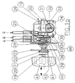
- FIG. 1 a shows a drive according to the invention partially broken open in longitudinal section
- FIG. 1 b shows the drive according to the invention according to FIG. 1 a with the housing removed
- FIG. 2 shows a section along the line AA of FIG. 1 a
- a worm shaft 30 is arranged, which interacts with a pulley 34 via a helical gear segment 33, the pulley being connected to the helical gear by means of rivets 35.
- a Bowden cable B3 which engages on the adjusting device for the backrest, is clamped onto the rope pulley 34.
- the control shaft 20 extends to the handwheel 43, via which the tensioning mechanism is actuated and the Bowden cable B3 moves, and thus an adjustment of the Backrest can be made.
- the control shaft 20 is surrounded by a tube 19, between which a latch spring 21 is arranged.
- a flange sleeve 42 runs over the selector shaft 20.
- a centering disk 24 is arranged on the flange sleeve 42 in the area of a housing 46 and is attached by means of a serrated lock washer or a snap ring 40 or a hexagon nut 41.
- the flange sleeve 42 widens within the holding plate 38 connected to the housing 46 and interacts with it.
- a cable pulley 25 is clamped, which is penetrated by a widened section of the control shaft 20, which as Switching unit is used.
- the rope pulley 25 is surrounded on one side by a stop spring 27 and interacts with it.
- the stop spring 27 is clamped on the holding plates 38 and can snap into recesses 44 in the cable pulley 25, as a result of which another Bowden cable B1 or B2 acting on the adjusting device for the backrest can be actuated.
- a latching spring 39 is provided which immediately acts as a stop in the longitudinal direction. It must also be effective in both directions, i.e. tension and compression springs at the same time.
- the two further Bowden cables B1 and B2 act on the cable pulley 25 in their peripheral region.
- the worm shaft can also be penetrated by the control shaft (not shown) and can either snap into a second or third turnbuckle and operate it. This creates a multi-function drive that allows the operation of several functions in a simple manner with one-hand operation.
- a loop, roller, wedge or free-wheel brake can also be switched on directly or indirectly in the tensioning mechanism, also externally via a Bowden cable, ie acting spatially separate from the backrest.
- the cable 45 is led into the interior of the lock shell 32 and immediately guided around the helical gear 33 by means of a spiral groove 47, which over part optionally as a toothless segment or the segment can be designed as a rope pulley.
- the helical gear 33 can be extended at one or both ends of the toothless segment, which may be designed as a rope pulley, in the direction of the center of the bearing journal 51 through the spiral groove 47, at the end of which a transverse hole 48, a depression or a threaded hole is provided , so that the rope end 49 can also be anchored within the helical tooth / rope pulley wheel, for example by a crimped nipple, cone or the like. A center of power is achieved.
- the holding plate 38 shown in Figs. 1 and 2 is e.g. by means of flat rivets 26 and a hexagon nut 36 with the two lock shells 32, which are held at a distance 50 of the helical gear 33 by means of spacers 31 and spacers 28 with pressed-in fillister head screw 29 according to FIG. 4.
Landscapes
- Engineering & Computer Science (AREA)
- Aviation & Aerospace Engineering (AREA)
- Transportation (AREA)
- Mechanical Engineering (AREA)
- Chairs For Special Purposes, Such As Reclining Chairs (AREA)
- Seats For Vehicles (AREA)
- Chair Legs, Seat Parts, And Backrests (AREA)
- Gear Transmission (AREA)
- Flexible Shafts (AREA)
Claims (8)
- Entraînement pour actionner un dossier de siège à déplacements multiples, comprenant un tendeur multiple (10) qui est traversé par un arbre (20), qui présente des mécanismes tendeurs individuels, ceux-ci agissant séparément et pouvant être actionnés au choix par déplacement de l'arbre (20), et qui est constitué par un arbre à vis sans fin (30) et par une roue tangente, cependant que tous les mécanismes tendeurs sont accouplés sur un arbre de commutation (20), que le tendeur (10) est séparé dans l'espace du dispositif de déplacement qui est destiné au dossier de siège et que les mécanismes tendeurs comprennent des câbles sous gaine (B1, B2, B3), caractérisé par le fait que les câbles sous gaine (B1, B2). peuvent être actionnés par l'intermédiaire d'une poulie (25) qui est montée sur l'arbre de commutation (20), et par le fait que la roue tangente comprend une poulie de renvoi (34) sur laquelle est placé un segment de roue dentée (33), un câble sous gaine (B3) étant serré dans la poulie de renvoi (34).
- Entraînement selon la revendication 1, caractérisé par le fait qu'un ressort d'encliquetage (39) est disposé entre l'arbre de commutation (20) et la poulie (25).
- Entraînement selon la revendication 2, caractérisé par le fait que le ressort d'encliquetage (39) peut être sollicité à la traction et à la compression, ainsi qu'en rappel élastique transversal, et qu'il constitue une butée pour le déplacement en rotation de l'arbre de commutation (20) dans la direction longitudinale du ressort.
- Entraînement selon la revendication 1, caractérisé par le fait qu'un câble sous gaine passe directement autour de la roue hélicoïdale (33) qui est réalisée le cas échéant, sur l'une de ses parties, sous la forme d'un segment sans dents ou d'un segment d'une poulie de renvoi (34).
- Entraînement selon la revendication 4, caractérisé par le fait que la roue hélicoïdale (33) est prolongée à l'une des extrémités du segment de la poulie de renvoi (34), ou des deux, dans la direction du centre d'un goujon formant palier (51), par une rainure en spirale (47) sur l'extrémité intérieure de laquelle est prévu un système de fixation (48) qui est destiné à un câble sous gaine (45, 49).
- Entraînenent selon la revendication 2, caractérisé par le fait qu'un ressort (27) agissant comme une butée pénètre dans la poulie (25).
- Entraînement selon la revendication 6, caractérisé par le fait que la poulie (25) est pourvue d'évidements (44) qui sont destinés au ressort (27).
- Entraînement selon l'une des revendications 1 à 7, caractérisé par le fait qu'un ou plusieurs freins à roue libre simples ou doubles sont montés sur l'arbre de commutation (20) à la place du mécanisme à vis sans fin ou en étant accouplés à celui-ci.
Applications Claiming Priority (3)
| Application Number | Priority Date | Filing Date | Title |
|---|---|---|---|
| AT18709/91 | 1991-09-17 | ||
| AT187091 | 1991-09-17 | ||
| PCT/AT1992/000119 WO1993005982A1 (fr) | 1991-09-17 | 1992-09-17 | Dispositif d'entrainement pour l'actionnement de dossiers a positions reglables multiples |
Publications (2)
| Publication Number | Publication Date |
|---|---|
| EP0604532A1 EP0604532A1 (fr) | 1994-07-06 |
| EP0604532B1 true EP0604532B1 (fr) | 1996-05-29 |
Family
ID=3522791
Family Applications (1)
| Application Number | Title | Priority Date | Filing Date |
|---|---|---|---|
| EP92920077A Expired - Lifetime EP0604532B1 (fr) | 1991-09-17 | 1992-09-17 | Dispositif d'entrainement pour l'actionnement de dossiers a positions reglables multiples |
Country Status (8)
| Country | Link |
|---|---|
| EP (1) | EP0604532B1 (fr) |
| JP (1) | JP2856911B2 (fr) |
| AT (1) | ATE138617T1 (fr) |
| AU (1) | AU671600B2 (fr) |
| CA (1) | CA2119353A1 (fr) |
| DE (1) | DE59206438D1 (fr) |
| ES (1) | ES2088594T3 (fr) |
| WO (1) | WO1993005982A1 (fr) |
Cited By (1)
| Publication number | Priority date | Publication date | Assignee | Title |
|---|---|---|---|---|
| DE10012758A1 (de) * | 2000-03-16 | 2001-09-20 | Volkswagen Ag | Verstellschalteranordnung zur elektrischen Verstellung eines Kraftfahrzeugsitzes |
Families Citing this family (3)
| Publication number | Priority date | Publication date | Assignee | Title |
|---|---|---|---|---|
| WO1996000666A1 (fr) * | 1994-06-28 | 1996-01-11 | Brose Fahrzeugteile Gmbh & Co. Kommanditgesellschaft | Systeme de reglage rapide, manuel et passif |
| GB0008130D0 (en) * | 2000-04-03 | 2000-05-24 | Youngflex Ag | Manual actuating means |
| DE102011016646A1 (de) | 2011-04-09 | 2012-10-11 | GM Global Technology Operations LLC (n. d. Gesetzen des Staates Delaware) | Rückenlehnenverstellvorrichtung für einen Fahrzeugsitz oder eine Fahrzeugsitzbank |
Family Cites Families (9)
| Publication number | Priority date | Publication date | Assignee | Title |
|---|---|---|---|---|
| DE332003C (de) * | 1919-06-05 | 1921-01-19 | Schweizerische Sodafabrik | Verfahren zur Kaustizierung von Soda in der Kaelte |
| AT377484B (de) * | 1978-09-06 | 1985-03-25 | Steyr Daimler Puch Ag | Rueckenlehne, insbesondere fuer kraftfahrzeugsitze |
| DE3204540A1 (de) * | 1982-02-10 | 1983-08-18 | Peter 5000 Köln Backsmann | Rueckenstuetze, insbesondere fuer kraftfahrzeugsitze |
| DE3307049C2 (de) * | 1983-02-28 | 1985-09-12 | P.A. Rentrop Hubbert & Wagner Fahrzeugausstattungen GmbH & Co KG, 3060 Stadthagen | Vorrichtung zum Verstellen eines Gegenstandes |
| DE3319397C2 (de) * | 1983-05-28 | 1986-12-18 | P.A. Rentrop, Hubbert & Wagner Fahrzeugausstattungen Gmbh & Co Kg, 3060 Stadthagen | Gelenkbeschlag für einen Sitz mit verstellbarer Rückenlehne, insbesondere Kraftfahrzeugsitz |
| DE3532295A1 (de) * | 1985-09-11 | 1987-03-19 | Schmitz & Co | Betaetigungsanordnung fuer beschlagelemente an kfz-sitzen |
| SE464287B (sv) * | 1987-10-12 | 1991-04-08 | Haakansson Bengt E W | Anordning foer att reglera objekt i foerarmiljoen i ett fordon |
| DE8801833U1 (de) * | 1988-02-12 | 1988-03-31 | Keiper Recaro GmbH & Co, 5630 Remscheid | Rückenlehne für einen Fahrzeugsitz |
| DE3817086A1 (de) * | 1988-05-19 | 1989-11-30 | Daimler Benz Ag | Einstellbare lendenstuetze fuer eine rueckenlehne |
-
1992
- 1992-09-17 AT AT92920077T patent/ATE138617T1/de not_active IP Right Cessation
- 1992-09-17 AU AU25856/92A patent/AU671600B2/en not_active Ceased
- 1992-09-17 JP JP5505612A patent/JP2856911B2/ja not_active Expired - Fee Related
- 1992-09-17 ES ES92920077T patent/ES2088594T3/es not_active Expired - Lifetime
- 1992-09-17 DE DE59206438T patent/DE59206438D1/de not_active Expired - Fee Related
- 1992-09-17 WO PCT/AT1992/000119 patent/WO1993005982A1/fr not_active Ceased
- 1992-09-17 EP EP92920077A patent/EP0604532B1/fr not_active Expired - Lifetime
- 1992-09-17 CA CA002119353A patent/CA2119353A1/fr not_active Abandoned
Cited By (2)
| Publication number | Priority date | Publication date | Assignee | Title |
|---|---|---|---|---|
| DE10012758A1 (de) * | 2000-03-16 | 2001-09-20 | Volkswagen Ag | Verstellschalteranordnung zur elektrischen Verstellung eines Kraftfahrzeugsitzes |
| DE10012758B4 (de) * | 2000-03-16 | 2009-12-17 | Volkswagen Ag | Verstellschalteranordnung zur elektrischen Verstellung eines Kraftfahrzeugsitzes |
Also Published As
| Publication number | Publication date |
|---|---|
| EP0604532A1 (fr) | 1994-07-06 |
| WO1993005982A1 (fr) | 1993-04-01 |
| AU671600B2 (en) | 1996-09-05 |
| AU2585692A (en) | 1993-04-27 |
| ES2088594T3 (es) | 1996-08-16 |
| JP2856911B2 (ja) | 1999-02-10 |
| ATE138617T1 (de) | 1996-06-15 |
| CA2119353A1 (fr) | 1993-04-01 |
| DE59206438D1 (de) | 1996-07-04 |
| JPH07502707A (ja) | 1995-03-23 |
Similar Documents
| Publication | Publication Date | Title |
|---|---|---|
| DE69811988T2 (de) | Neigungsvorrichtung | |
| EP0743221B2 (fr) | Mécanisme de réglage pour sièges de véhicules automobiles | |
| EP2448703B1 (fr) | Dispositif de perçage | |
| EP0175996A2 (fr) | Unité d'entraînement notamment pour le déplacement de glaces, de toits ouvrants, de sièges et d'accessoires d'automobiles similaires | |
| DE112012005856B4 (de) | Lenkeinrichtung für ein Fahrzeug | |
| EP0604532B1 (fr) | Dispositif d'entrainement pour l'actionnement de dossiers a positions reglables multiples | |
| DE2614684A1 (de) | Ratschen-schaltgetriebe | |
| DE102004042574A1 (de) | Scheibenbremse, insbesondere für Nutzfahrzeuge | |
| EP0230849A1 (fr) | Soupape de réglage/soupape d'arrêt | |
| DE3407159A1 (de) | Vorrichtung zur veraenderung der neigung der rueckenlehne eines fahrzeugsitzes | |
| DE4437539A1 (de) | Fahrzeugsitz mit einer Längsverstellvorrichtung und einer Sitztiefenverstellung der Sitzfläche | |
| DE3424109A1 (de) | Vorrichtung zum ankoppeln, wie z.b. bremse o.dgl., mit einer verschleissnachstelleinrichtung | |
| EP0839702A2 (fr) | Dispositif de serrage pour une colonne de direction réglable | |
| EP4107048A1 (fr) | Commande de réglage conçue pour une colonne de direction, et colonne de direction réglable par moteur pour un véhicule automobile | |
| DE29909044U1 (de) | Armlehne für einen Fahrzeugsitz | |
| DE60318973T2 (de) | Bremspedal- Nachstellungmechanismus | |
| DE10218568A1 (de) | Höhenverstelleinrichtung an einem Fahrzeugsitz | |
| AT410828B (de) | Vorrichtung zur betätigung eines kabelzuges | |
| DE102019110911B4 (de) | Türfeststeller | |
| DE29710192U1 (de) | Neigungsverstelleinrichtung für eine Kraftfahrzeugsitz-Rückenlehne | |
| DE19923668C1 (de) | Armlehne für einen Fahrzeugsitz | |
| DE3039968A1 (de) | Schaltwerk | |
| EP0235212A1 (fr) | Dispositif de tour pour guider ou serrer des barres | |
| DE102006009957B3 (de) | Bowdenzugblockiereinrichtung | |
| DE102024105319B3 (de) | Stellvorrichtung mit flexiblem Hilfsantrieb |
Legal Events
| Date | Code | Title | Description |
|---|---|---|---|
| PUAI | Public reference made under article 153(3) epc to a published international application that has entered the european phase |
Free format text: ORIGINAL CODE: 0009012 |
|
| 17P | Request for examination filed |
Effective date: 19940304 |
|
| AK | Designated contracting states |
Kind code of ref document: A1 Designated state(s): AT CH DE ES FR GB IT LI NL SE |
|
| 17Q | First examination report despatched |
Effective date: 19950707 |
|
| GRAH | Despatch of communication of intention to grant a patent |
Free format text: ORIGINAL CODE: EPIDOS IGRA |
|
| GRAA | (expected) grant |
Free format text: ORIGINAL CODE: 0009210 |
|
| AK | Designated contracting states |
Kind code of ref document: B1 Designated state(s): AT CH DE ES FR GB IT LI NL SE |
|
| PG25 | Lapsed in a contracting state [announced via postgrant information from national office to epo] |
Ref country code: NL Free format text: LAPSE BECAUSE OF FAILURE TO SUBMIT A TRANSLATION OF THE DESCRIPTION OR TO PAY THE FEE WITHIN THE PRESCRIBED TIME-LIMIT Effective date: 19960529 |
|
| REF | Corresponds to: |
Ref document number: 138617 Country of ref document: AT Date of ref document: 19960615 Kind code of ref document: T |
|
| REF | Corresponds to: |
Ref document number: 59206438 Country of ref document: DE Date of ref document: 19960704 |
|
| REG | Reference to a national code |
Ref country code: ES Ref legal event code: BA2A Ref document number: 2088594 Country of ref document: ES Kind code of ref document: T3 |
|
| REG | Reference to a national code |
Ref country code: CH Ref legal event code: NV Representative=s name: E. BLUM & CO. PATENTANWAELTE |
|
| ITF | It: translation for a ep patent filed | ||
| REG | Reference to a national code |
Ref country code: ES Ref legal event code: FG2A Ref document number: 2088594 Country of ref document: ES Kind code of ref document: T3 |
|
| PG25 | Lapsed in a contracting state [announced via postgrant information from national office to epo] |
Ref country code: SE Effective date: 19960829 |
|
| ET | Fr: translation filed | ||
| GBT | Gb: translation of ep patent filed (gb section 77(6)(a)/1977) |
Effective date: 19960903 |
|
| NLV1 | Nl: lapsed or annulled due to failure to fulfill the requirements of art. 29p and 29m of the patents act | ||
| PLBE | No opposition filed within time limit |
Free format text: ORIGINAL CODE: 0009261 |
|
| STAA | Information on the status of an ep patent application or granted ep patent |
Free format text: STATUS: NO OPPOSITION FILED WITHIN TIME LIMIT |
|
| 26N | No opposition filed | ||
| REG | Reference to a national code |
Ref country code: CH Ref legal event code: PUE Owner name: SCHUSTER, WILHELM, SEN. TRANSFER- SCHUKRA-GERAETEB |
|
| REG | Reference to a national code |
Ref country code: FR Ref legal event code: TP |
|
| PGFP | Annual fee paid to national office [announced via postgrant information from national office to epo] |
Ref country code: AT Payment date: 20010925 Year of fee payment: 10 |
|
| PGFP | Annual fee paid to national office [announced via postgrant information from national office to epo] |
Ref country code: ES Payment date: 20011001 Year of fee payment: 10 |
|
| REG | Reference to a national code |
Ref country code: GB Ref legal event code: IF02 |
|
| PGFP | Annual fee paid to national office [announced via postgrant information from national office to epo] |
Ref country code: FR Payment date: 20020910 Year of fee payment: 11 |
|
| PGFP | Annual fee paid to national office [announced via postgrant information from national office to epo] |
Ref country code: DE Payment date: 20020913 Year of fee payment: 11 |
|
| PGFP | Annual fee paid to national office [announced via postgrant information from national office to epo] |
Ref country code: GB Payment date: 20020916 Year of fee payment: 11 |
|
| PG25 | Lapsed in a contracting state [announced via postgrant information from national office to epo] |
Ref country code: AT Free format text: LAPSE BECAUSE OF NON-PAYMENT OF DUE FEES Effective date: 20020917 |
|
| PG25 | Lapsed in a contracting state [announced via postgrant information from national office to epo] |
Ref country code: ES Free format text: LAPSE BECAUSE OF NON-PAYMENT OF DUE FEES Effective date: 20020918 |
|
| PGFP | Annual fee paid to national office [announced via postgrant information from national office to epo] |
Ref country code: CH Payment date: 20020927 Year of fee payment: 11 |
|
| PG25 | Lapsed in a contracting state [announced via postgrant information from national office to epo] |
Ref country code: GB Free format text: LAPSE BECAUSE OF NON-PAYMENT OF DUE FEES Effective date: 20030917 |
|
| PG25 | Lapsed in a contracting state [announced via postgrant information from national office to epo] |
Ref country code: LI Free format text: LAPSE BECAUSE OF NON-PAYMENT OF DUE FEES Effective date: 20030930 Ref country code: CH Free format text: LAPSE BECAUSE OF NON-PAYMENT OF DUE FEES Effective date: 20030930 |
|
| PG25 | Lapsed in a contracting state [announced via postgrant information from national office to epo] |
Ref country code: DE Free format text: LAPSE BECAUSE OF NON-PAYMENT OF DUE FEES Effective date: 20040401 |
|
| REG | Reference to a national code |
Ref country code: ES Ref legal event code: FD2A Effective date: 20031011 |
|
| GBPC | Gb: european patent ceased through non-payment of renewal fee |
Effective date: 20030917 |
|
| REG | Reference to a national code |
Ref country code: CH Ref legal event code: PL |
|
| PG25 | Lapsed in a contracting state [announced via postgrant information from national office to epo] |
Ref country code: FR Free format text: LAPSE BECAUSE OF NON-PAYMENT OF DUE FEES Effective date: 20040528 |
|
| REG | Reference to a national code |
Ref country code: FR Ref legal event code: ST |
|
| PG25 | Lapsed in a contracting state [announced via postgrant information from national office to epo] |
Ref country code: IT Free format text: LAPSE BECAUSE OF NON-PAYMENT OF DUE FEES Effective date: 20050917 |