EP0604695A1 - Procédé et dispositif pour fabriquer un curseur pour fermeture à glissière - Google Patents
Procédé et dispositif pour fabriquer un curseur pour fermeture à glissière Download PDFInfo
- Publication number
- EP0604695A1 EP0604695A1 EP92811027A EP92811027A EP0604695A1 EP 0604695 A1 EP0604695 A1 EP 0604695A1 EP 92811027 A EP92811027 A EP 92811027A EP 92811027 A EP92811027 A EP 92811027A EP 0604695 A1 EP0604695 A1 EP 0604695A1
- Authority
- EP
- European Patent Office
- Prior art keywords
- mold
- zipper
- mold cores
- tool according
- pull tab
- Prior art date
- Legal status (The legal status is an assumption and is not a legal conclusion. Google has not performed a legal analysis and makes no representation as to the accuracy of the status listed.)
- Granted
Links
Images


Classifications
-
- B—PERFORMING OPERATIONS; TRANSPORTING
- B29—WORKING OF PLASTICS; WORKING OF SUBSTANCES IN A PLASTIC STATE IN GENERAL
- B29C—SHAPING OR JOINING OF PLASTICS; SHAPING OF MATERIAL IN A PLASTIC STATE, NOT OTHERWISE PROVIDED FOR; AFTER-TREATMENT OF THE SHAPED PRODUCTS, e.g. REPAIRING
- B29C45/00—Injection moulding, i.e. forcing the required volume of moulding material through a nozzle into a closed mould; Apparatus therefor
- B29C45/0017—Injection moulding, i.e. forcing the required volume of moulding material through a nozzle into a closed mould; Apparatus therefor moulding interconnected elements which are movable with respect to one another, e.g. chains or hinges
-
- A—HUMAN NECESSITIES
- A44—HABERDASHERY; JEWELLERY
- A44B—BUTTONS, PINS, BUCKLES, SLIDE FASTENERS, OR THE LIKE
- A44B19/00—Slide fasteners
- A44B19/24—Details
- A44B19/26—Sliders
-
- A—HUMAN NECESSITIES
- A44—HABERDASHERY; JEWELLERY
- A44B—BUTTONS, PINS, BUCKLES, SLIDE FASTENERS, OR THE LIKE
- A44B19/00—Slide fasteners
- A44B19/24—Details
- A44B19/26—Sliders
- A44B19/30—Sliders with means for locking in position
- A44B19/303—Self-locking sliders, e.g. slider body provided with locking projection or groove, friction means
-
- B—PERFORMING OPERATIONS; TRANSPORTING
- B29—WORKING OF PLASTICS; WORKING OF SUBSTANCES IN A PLASTIC STATE IN GENERAL
- B29C—SHAPING OR JOINING OF PLASTICS; SHAPING OF MATERIAL IN A PLASTIC STATE, NOT OTHERWISE PROVIDED FOR; AFTER-TREATMENT OF THE SHAPED PRODUCTS, e.g. REPAIRING
- B29C45/00—Injection moulding, i.e. forcing the required volume of moulding material through a nozzle into a closed mould; Apparatus therefor
- B29C45/17—Component parts, details or accessories; Auxiliary operations
- B29C45/26—Moulds
- B29C45/33—Moulds having transversely, e.g. radially, movable mould parts
- B29C45/332—Mountings or guides therefor; Drives therefor
-
- Y—GENERAL TAGGING OF NEW TECHNOLOGICAL DEVELOPMENTS; GENERAL TAGGING OF CROSS-SECTIONAL TECHNOLOGIES SPANNING OVER SEVERAL SECTIONS OF THE IPC; TECHNICAL SUBJECTS COVERED BY FORMER USPC CROSS-REFERENCE ART COLLECTIONS [XRACs] AND DIGESTS
- Y10—TECHNICAL SUBJECTS COVERED BY FORMER USPC
- Y10S—TECHNICAL SUBJECTS COVERED BY FORMER USPC CROSS-REFERENCE ART COLLECTIONS [XRACs] AND DIGESTS
- Y10S425/00—Plastic article or earthenware shaping or treating: apparatus
- Y10S425/814—Zipper
-
- Y—GENERAL TAGGING OF NEW TECHNOLOGICAL DEVELOPMENTS; GENERAL TAGGING OF CROSS-SECTIONAL TECHNOLOGIES SPANNING OVER SEVERAL SECTIONS OF THE IPC; TECHNICAL SUBJECTS COVERED BY FORMER USPC CROSS-REFERENCE ART COLLECTIONS [XRACs] AND DIGESTS
- Y10—TECHNICAL SUBJECTS COVERED BY FORMER USPC
- Y10T—TECHNICAL SUBJECTS COVERED BY FORMER US CLASSIFICATION
- Y10T24/00—Buckles, buttons, clasps, etc.
- Y10T24/25—Zipper or required component thereof
- Y10T24/2561—Slider having specific configuration, construction, adaptation, or material
- Y10T24/2566—Slider having specific configuration, construction, adaptation, or material including position locking-means attached thereto
- Y10T24/257—Slider having specific configuration, construction, adaptation, or material including position locking-means attached thereto having surface engaging element shifted by reorientation of pull tab
- Y10T24/2571—Resilient or spring biased element
Definitions
- the present invention relates to a method for producing zipper sliders, in particular by injection molding, in which the pull tab of the zipper slider is injected together with the slider body.
- a method for spraying a zipper pull with a pull tab is described in European Patent No. 0 282 987.
- the slide body is injected in a first spraying step.
- the bracket on the slide body which later receives the pull tab, is formed by an inserted mold core with a displaceably inserted auxiliary core.
- the auxiliary core is pulled out to inject the pull tab. This results in a spray channel that runs under the bracket of the slide body.
- the injection compound for the pull tab is then injected. Before the finished zipper slider with pull tab is ejected, the mandrel is then pulled out of the mold again.
- the disadvantage of this method is that the spraying process takes place in two courses.
- spraying the pull tab wait until the material of the slide body is sufficiently hardened so that the spray material of the pull tab does not bond with that of the body, since the spray material for the pull tab comes into direct contact with that of the slide body.
- An object of the present invention is to provide a method in which the zipper slider body and the pull tab are produced in a single injection cycle. Such a method is specified in claim 1.
- the further claims define preferred embodiments, Tools for carrying out the method and zipper pulls produced therewith.
- four mold cores are inserted into a mold in an approximately cross shape until they touch.
- the abutment surfaces are shaped in such a way that they form in particular the bracket attached to the slide body and the transverse web of the pull tab that passes between the bracket and the slide body.
- two of the mold cores additionally have projections which separate the connection between the rear bracket end and the slide body. This gives a rear section of the slider body which is only elastically connected to the rest of the slider body via the bracket. A cam can be formed on this section, which protrudes into the space between the links of the zipper tape. You get a self-locking zipper slider. The lock is released when the pull tab is pulled forwards or backwards, and the brackets are bent upwards by means of a wedge effect and the cam is pulled out of the zipper band.
- Fig. 1 shows a zipper slider 1 produced according to the invention with a pull tab 2 and a slider body 3.
- the bracket 4 spans the slider body 3 and serves to fasten the pull tab 2.
- the body 3 consists of the upper plate 5 and the lower plate 6, which over the separating wedge 7 are connected.
- the separating wedge 7, together with the side guides 8 and 9 on the upper base plate 5 and the lower base plate 6, serves in a known manner to guide the link belts during the opening or closing of the zipper.
- the blocking cam 10 is, as shown in FIGS. 2 and 3, formed on a wedge-shaped section 11 of the upper plate 5.
- the section 11 is separated from the rest of the base plate 5 by a gap 12 and is therefore only connected to the slide body 3 via the bracket 4.
- the gap 12 is preferably stepped, so that when the pull tab 2 is pulled and the part 11 is moved upward via the bracket 4, the projection 13 of part 11 strikes the projection 14 on the upper base plate 5 and thus the upward movement is stopped.
- the locking cam 10 is pulled out of the space between the zipper members, and the slider 1 can be pulled over the zipper straps, while in the idle state, ie without pulling on the pull tab 2, the locking cam 10 projects into the space between two zipper members and thus the Movement of slide 1 blocked.
- side guides can be shaped in the so-called "wing-lock” version as shown in FIG. 2.
- the ends of the side guides 8 and 9 leading to the separating wedge 7 can hook into the rear ends of the zipper members and thus relieve the locking cam 10.
- a depression 15 is advantageously also formed in the upper base plate 5.
- the pull tab 2 must then be pulled over the edges of the recess 15 with a certain amount of force to unlock the slide.
- FIG. 4 shows a section through a tool for producing the zipper slider 1. It consists of the front tool half 21 and the rear tool half 22.
- the front tool half 21 consists of the actuating plate 24 and the die 25.
- the actuating plate 24 also has claws 26 , the projections 27 on the die 25 engage behind with play. This arrangement acts as a limitation for a relative movement of the die 25 with respect to the actuating plate 24.
- the rear tool 22 is essentially a mirror image of the front tool 21. Instead of the ejectors 29 to 31, however, the sprue 33 runs through the actuating plate 34 and the die 35 to the channel 36, which feeds the spray compound to the molds for the zipper slider 1.
- the dies 25 and 35 have the casting molds for the zipper slider body and the pull tab in a substantially known manner.
- four mold cores 37-40 are additionally arranged to be longitudinally displaceable in the two dies 25 and 35.
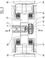
- the section in FIG. 5 shows that the mandrels 37 to 40 are arranged approximately in the manner of a cross. They can move along the arms of the cross and are pushed together towards the center of the cross during the spraying process, their front surfaces touching and completing the shape for the zipper slider 1. In particular, they form the shape for the web 41 of the pull tab 1, which passes through the eyelet formed between the bracket 4 and the upper plate 5.
- the mold cores 37 and 38 are also part of the mold for the front half of the bracket 4, in particular for the surface facing the aforementioned eyelet.
- the mandrels 39 to 40 form the shape for the surface of the rear half of the bracket 4 facing the eyelet.
- FIG. 6 shows, the shape incorporated in the dies 25 and 35 is separated into two completely separate shapes by the mandrels 37 and 40 divided the slider body 3 and the pull tab 2. Both parts can therefore be sprayed at the same time.
- the recess 15 can also be formed, which widens conically towards the periphery of the upper plate 5 due to the direction of movement of the mold cores.
- the mold cores 39 and 40 can additionally on the underside Have projections that form the gap 12 between the wedge-shaped part 11 and the upper base plate 5.
- the locking cam 10 formed on the part 11 is formed by a recess in one of the projections 43 and / or 42 of the dies 25 and 35, respectively, which model the interior of the slide body 3.
- the mold cores 37 to 40 each have a roller 44 at their rear end and are pressed outwards by at least one compression spring 47, i.e. pushed away from the center of the cross, whereby the rollers 44 are pressed against the pressure pieces 45 on the actuating plates 24 and 25, respectively.
- the actuator plates 34 and 24 are moved away from the respective dies 25.
- the mold cores 37 to 40 extend from the interior of the dies 25 and 35 under the pressure of the respective spring 47. This process ends when the respective claws 26 of the actuating plates 24 and 34 strike the projections 27 of the respective dies 25 and 35, respectively.
- the mold cores 37 to 40 are then extended so far that the tool can be opened.
- the actuating plate 24 in FIG. 5 can be moved further to the right, the die 25 being taken along, and the ejectors 29, 30 and 31 can push the finished zipper slider including the pull tab out of the die.
- FIG. 7 shows a variant of the tool.
- the representation is analogous to FIG. 5 and uses the same reference numbers, unless otherwise defined.
- the pressure pieces 45 are essentially replaced by the wedges 51, which can move in the space between the guide plates 57 and 58 and the dies 25 and 35, respectively.
- the guide plates 57 and 58 are mounted at a fixed distance from the respective die 25 or 35, so that the wedges 51 are guided with high precision.
- the mandrels 37 to 40 have sliding surfaces 52 with which they can slide over the bevels 53 of the wedges 51 with little friction.
- the wedges 51 each have a pin 54 at their outer end, which engages in a groove 55 in a control piece 56.
- the control pieces 56 are attached to the die 35 or to the actuating plate 34.
- the wedges 51 are inserted at precisely defined positions via highly precise slideways 61 which cooperate with corresponding bevels 62 on the wedges 51. If the actuating plates 24 move away from the dies 25 and 35 when the mold is opened, the pins 54 and subsequently also the wedges 51 slide outwards, and the mold cores 37 to 40 can move out of the mold.
- FIG. 8 shows a partial top view of the die 25 of the front tool 21 with a preferred embodiment of the channel 36.
- one channel 59 is required for the material for spraying the pull tab and a second one Channel 58 for the material for spraying the body 3.
Landscapes
- Engineering & Computer Science (AREA)
- Manufacturing & Machinery (AREA)
- Mechanical Engineering (AREA)
- Slide Fasteners (AREA)
- Moulds For Moulding Plastics Or The Like (AREA)
- Bag Frames (AREA)
Priority Applications (6)
| Application Number | Priority Date | Filing Date | Title |
|---|---|---|---|
| EP92811027A EP0604695B1 (fr) | 1992-12-29 | 1992-12-29 | Procédé et dispositif pour fabriquer un curseur pour fermeture à glissière |
| AT92811027T ATE135623T1 (de) | 1992-12-29 | 1992-12-29 | Verfahren und werkzeug zur herstellung eines reissverschlussschiebers |
| DK92811027.9T DK0604695T3 (da) | 1992-12-29 | 1992-12-29 | Fremgangsmåde og værktøj til fremstilling af en lynlåsskyder |
| ES92811027T ES2084980T3 (es) | 1992-12-29 | 1992-12-29 | Procedimiento y molde para la fabricacion de una corredera de cremallera. |
| DE59205782T DE59205782D1 (de) | 1992-12-29 | 1992-12-29 | Verfahren und Werkzeug zur Herstellung eines Reissverschlussschiebers |
| US08/516,932 US5604962A (en) | 1992-12-29 | 1995-08-18 | Zipper slide |
Applications Claiming Priority (1)
| Application Number | Priority Date | Filing Date | Title |
|---|---|---|---|
| EP92811027A EP0604695B1 (fr) | 1992-12-29 | 1992-12-29 | Procédé et dispositif pour fabriquer un curseur pour fermeture à glissière |
Publications (2)
| Publication Number | Publication Date |
|---|---|
| EP0604695A1 true EP0604695A1 (fr) | 1994-07-06 |
| EP0604695B1 EP0604695B1 (fr) | 1996-03-20 |
Family
ID=8212058
Family Applications (1)
| Application Number | Title | Priority Date | Filing Date |
|---|---|---|---|
| EP92811027A Expired - Lifetime EP0604695B1 (fr) | 1992-12-29 | 1992-12-29 | Procédé et dispositif pour fabriquer un curseur pour fermeture à glissière |
Country Status (6)
| Country | Link |
|---|---|
| US (1) | US5604962A (fr) |
| EP (1) | EP0604695B1 (fr) |
| AT (1) | ATE135623T1 (fr) |
| DE (1) | DE59205782D1 (fr) |
| DK (1) | DK0604695T3 (fr) |
| ES (1) | ES2084980T3 (fr) |
Cited By (7)
| Publication number | Priority date | Publication date | Assignee | Title |
|---|---|---|---|---|
| US5698243A (en) * | 1995-04-17 | 1997-12-16 | Ykk Corporation | Mold apparatus for simultaneously molding two cross-linked annular parts |
| EP0804886A3 (fr) * | 1996-04-30 | 1998-06-03 | Ykk Corporation | Curseur à verrouillage automatique et appareillage de moulage du couvercle du curseur |
| EP0850577A3 (fr) * | 1996-12-27 | 1999-01-13 | Ykk Corporation | Curseur pour fermeture à glissière et son moule métallique |
| US7674106B2 (en) * | 2006-08-16 | 2010-03-09 | Hon Hai Precision Industry Co., Ltd. | Molding apparatus |
| EP2891551A1 (fr) | 2014-01-07 | 2015-07-08 | Speedomatic AG | Outil de moulage par injection pour la fabrication d'un curseur de fermeture à glissière et la même fermeture à glissière |
| WO2019020174A1 (fr) | 2017-07-25 | 2019-01-31 | Delsey | Curseur de sécurité pour une fermeture à glissière |
| CN111152414A (zh) * | 2020-01-16 | 2020-05-15 | 浙江普光窗饰有限公司 | 一种球环形壳体用合金注塑模具 |
Families Citing this family (16)
| Publication number | Priority date | Publication date | Assignee | Title |
|---|---|---|---|---|
| JPH1057118A (ja) * | 1996-08-20 | 1998-03-03 | Ykk Corp | スライドファスナー用スライダーの胴体成形方法及びその成形金型 |
| JP3320636B2 (ja) * | 1997-06-12 | 2002-09-03 | ワイケイケイ株式会社 | インサート成形機における引手付ファスナー用スライダーの引手挿入ユニット |
| JP3560118B2 (ja) * | 1997-09-19 | 2004-09-02 | Ykk株式会社 | スライドファスナー用スライダーおよびその成形金型 |
| CN1105629C (zh) * | 1999-09-13 | 2003-04-16 | 郑荣元 | 具有成型枢转部位的塑胶模具 |
| US20080052880A1 (en) * | 2006-09-01 | 2008-03-06 | Warren Ware Sullivan | Locking slide for securely locking a zipper |
| US20080292837A1 (en) * | 2007-05-21 | 2008-11-27 | Mackal Glenn H | Apparatus and Method for Injection Molding a Fully-Assembled Multi-Component Articulatable Device |
| US11006703B2 (en) | 2016-04-01 | 2021-05-18 | Shah Technologies, LLC | Metal one piece slide and pull for slide fastener |
| US10064457B2 (en) | 2016-12-20 | 2018-09-04 | Shah Technologies, LLC | Metal one piece locking slide and pull for slide fastener |
| JP7084909B2 (ja) | 2016-04-01 | 2022-06-15 | シャー テクノロジーズ エルエルシー | スライドファスナのための金属一体ロックスライドおよび引手 |
| US11432621B2 (en) | 2016-04-01 | 2022-09-06 | Shah Technologies, LLC | Metal one piece security slide and pull for slide fastener |
| US10064455B2 (en) | 2016-04-01 | 2018-09-04 | Shah Technologies, LLC | Metal one piece slide and pull for slide fastener |
| CN108688064A (zh) * | 2017-04-12 | 2018-10-23 | 浙江伟星实业发展股份有限公司 | 一种注塑拉链排牙设备 |
| CN110216846A (zh) * | 2018-03-04 | 2019-09-10 | 赵红艳 | 一种内外双抽芯结构抽芯机构 |
| JP6518806B2 (ja) * | 2018-03-09 | 2019-05-22 | Ykk株式会社 | スライドファスナー用スライダー及びスライドファスナー |
| AU2019329962B2 (en) | 2018-08-31 | 2025-05-01 | Shah Technologies, LLC | Metal one piece slide and pull for slide fastener |
| KR20240022492A (ko) | 2021-05-14 | 2024-02-20 | 스하 테크놀로지스 엘엘씨 | 슬라이드 패스너용 금속 일체형 보안 슬라이드 및 당김 부재 |
Citations (5)
| Publication number | Priority date | Publication date | Assignee | Title |
|---|---|---|---|---|
| US2509278A (en) * | 1946-02-07 | 1950-05-30 | Conmar Prod Corp | Mold for producing interlocked slider bodies and pull for slide fasteners |
| US2736062A (en) * | 1956-02-28 | scheuermann etal | ||
| FR2145453A1 (fr) * | 1971-07-12 | 1973-02-23 | Terracina Silvano | |
| US4210196A (en) * | 1978-06-01 | 1980-07-01 | Lewis Weiner | Die casting apparatus |
| US5073103A (en) * | 1990-10-01 | 1991-12-17 | Hseng Chee Enterprise Pte, Ltd | Integral sliding member of a slide fastener and the molding device thereof |
Family Cites Families (6)
| Publication number | Priority date | Publication date | Assignee | Title |
|---|---|---|---|---|
| US1890336A (en) * | 1931-06-02 | 1932-12-06 | Frank E Nodine | Locking means |
| US2274161A (en) * | 1938-06-30 | 1942-02-24 | Talon Inc | Molded slider for slide fasteners |
| DE1608787B1 (de) * | 1962-05-15 | 1969-09-04 | Bjoerklund Geb Simberg | Dauerform zum Giessen eines Reissverschlussschlosses |
| NL6703918A (fr) * | 1966-04-01 | 1967-10-02 | ||
| EP0356600B1 (fr) * | 1988-07-15 | 1993-04-07 | Opti Patent-, Forschungs- und Fabrikations-AG | Procédé et machine pour fabriquer des fermetures à glissière |
| DE4139480C2 (de) * | 1991-11-29 | 1995-03-23 | M & S Werkzeugbau Ges M B H | Schieber für einen Reissverschluß |
-
1992
- 1992-12-29 AT AT92811027T patent/ATE135623T1/de active
- 1992-12-29 DK DK92811027.9T patent/DK0604695T3/da active
- 1992-12-29 ES ES92811027T patent/ES2084980T3/es not_active Expired - Lifetime
- 1992-12-29 DE DE59205782T patent/DE59205782D1/de not_active Expired - Lifetime
- 1992-12-29 EP EP92811027A patent/EP0604695B1/fr not_active Expired - Lifetime
-
1995
- 1995-08-18 US US08/516,932 patent/US5604962A/en not_active Expired - Lifetime
Patent Citations (5)
| Publication number | Priority date | Publication date | Assignee | Title |
|---|---|---|---|---|
| US2736062A (en) * | 1956-02-28 | scheuermann etal | ||
| US2509278A (en) * | 1946-02-07 | 1950-05-30 | Conmar Prod Corp | Mold for producing interlocked slider bodies and pull for slide fasteners |
| FR2145453A1 (fr) * | 1971-07-12 | 1973-02-23 | Terracina Silvano | |
| US4210196A (en) * | 1978-06-01 | 1980-07-01 | Lewis Weiner | Die casting apparatus |
| US5073103A (en) * | 1990-10-01 | 1991-12-17 | Hseng Chee Enterprise Pte, Ltd | Integral sliding member of a slide fastener and the molding device thereof |
Cited By (11)
| Publication number | Priority date | Publication date | Assignee | Title |
|---|---|---|---|---|
| US5698243A (en) * | 1995-04-17 | 1997-12-16 | Ykk Corporation | Mold apparatus for simultaneously molding two cross-linked annular parts |
| EP0804886A3 (fr) * | 1996-04-30 | 1998-06-03 | Ykk Corporation | Curseur à verrouillage automatique et appareillage de moulage du couvercle du curseur |
| US5848455A (en) * | 1996-04-30 | 1998-12-15 | Ykk Corporation | Auto-lock slide fastener slider and apparatus for molding slider cover |
| US6109908A (en) * | 1996-04-30 | 2000-08-29 | Ykk Corporation | Apparatus for molding a slider cover |
| EP0850577A3 (fr) * | 1996-12-27 | 1999-01-13 | Ykk Corporation | Curseur pour fermeture à glissière et son moule métallique |
| US5991981A (en) * | 1996-12-27 | 1999-11-30 | Ykk Corporation | Slider for slide fastener and a metal mold for the same |
| US6533239B1 (en) | 1996-12-27 | 2003-03-18 | Ykk Corporation | Metal mold for manufacturing a slider for a slide fastener |
| US7674106B2 (en) * | 2006-08-16 | 2010-03-09 | Hon Hai Precision Industry Co., Ltd. | Molding apparatus |
| EP2891551A1 (fr) | 2014-01-07 | 2015-07-08 | Speedomatic AG | Outil de moulage par injection pour la fabrication d'un curseur de fermeture à glissière et la même fermeture à glissière |
| WO2019020174A1 (fr) | 2017-07-25 | 2019-01-31 | Delsey | Curseur de sécurité pour une fermeture à glissière |
| CN111152414A (zh) * | 2020-01-16 | 2020-05-15 | 浙江普光窗饰有限公司 | 一种球环形壳体用合金注塑模具 |
Also Published As
| Publication number | Publication date |
|---|---|
| DE59205782D1 (de) | 1996-04-25 |
| US5604962A (en) | 1997-02-25 |
| DK0604695T3 (da) | 1996-04-15 |
| EP0604695B1 (fr) | 1996-03-20 |
| ES2084980T3 (es) | 1996-05-16 |
| ATE135623T1 (de) | 1996-04-15 |
Similar Documents
| Publication | Publication Date | Title |
|---|---|---|
| EP0604695B1 (fr) | Procédé et dispositif pour fabriquer un curseur pour fermeture à glissière | |
| DE69718743T2 (de) | Verfahren und Vorrichtung zur Herstellung von Bürstenkörpern für Zahnbürsten | |
| EP0356600B1 (fr) | Procédé et machine pour fabriquer des fermetures à glissière | |
| DE60132538T2 (de) | Einstellbare Nockenführung der Werkzeughälften einer Spritzgiessmaschine | |
| DE7835440U1 (de) | Form zur herstellung von formstuecken mit hintergreifenden teilen | |
| DE1529946B2 (de) | Spritzgiessform zum herstellen von hinterschneidungen auf weisenden behaeltern aus kunststoff | |
| DE2926985C2 (de) | Spritzgießvorrichtung zum intermittierenden Herstellen einer fortlaufenden Reißverschluß-Gliederkette | |
| DE3247723C2 (de) | Spritzgießform | |
| CH206488A (de) | Giessform für Kunststoffe. | |
| EP0620094B1 (fr) | Procédé et dispositif pour fabriquer une fermeture à glissière | |
| DE60104602T2 (de) | Befestigungstruktur eines Verbindergehäuses und einer von hinten angebrachten Kontakthalterung | |
| DE102006003588A1 (de) | Schnallenvorrichtung, Spritzwerkzeug und Spritzgießverfahren | |
| DE19949851C2 (de) | Kunststoff-Spritzgießmaschine, Handlingsystem sowie Verfahren zum Überführen eines Gegenstandes | |
| DE19528414A1 (de) | Vorrichtung zur Herstellung von Spritzguß-Formteilen | |
| DE2927060C2 (de) | Vorrichtung zum Spritzgießen einer fortlaufenden Reißverschlußkette | |
| DE202017101592U1 (de) | Druckgussform | |
| DE69801306T2 (de) | Metallische Spritzgiessform zur gratenfreien Herstellung von Produkten aus synthetischem Kunstharz | |
| EP0303834A1 (fr) | Moule d'injection | |
| DE813756C (de) | Verfahren zum automatischen Herstellen von Spritzgussstuecken | |
| AT506116B1 (de) | Verfahren zum betreiben einer spritzgiesseinrichtung | |
| DE102006016078A1 (de) | Druckgussform | |
| DE2727257C3 (de) | Niederdruckgießmaschine | |
| DE4203696C2 (de) | Vorrichtung zum Spritzgießen eines Formteils aus Kunststoff | |
| DE3040072A1 (de) | Spritzvorrichtung fuer das aufspritzen von anfangsstoppteilen und/oder entstoppteilen auf reissverschluss-halbzeugband | |
| DE1529946C (de) | Spritzgießform zum Herstellen von Hinterschneidungen aufweisenden Behaltern aus Kunststoff |
Legal Events
| Date | Code | Title | Description |
|---|---|---|---|
| PUAI | Public reference made under article 153(3) epc to a published international application that has entered the european phase |
Free format text: ORIGINAL CODE: 0009012 |
|
| AK | Designated contracting states |
Kind code of ref document: A1 Designated state(s): AT BE CH DE DK ES FR GB GR IE IT LI LU MC NL PT SE |
|
| 17P | Request for examination filed |
Effective date: 19940718 |
|
| RBV | Designated contracting states (corrected) |
Designated state(s): AT BE CH DE DK ES FR GB IT LI SE |
|
| 17Q | First examination report despatched |
Effective date: 19950831 |
|
| GRAH | Despatch of communication of intention to grant a patent |
Free format text: ORIGINAL CODE: EPIDOS IGRA |
|
| GRAA | (expected) grant |
Free format text: ORIGINAL CODE: 0009210 |
|
| ITF | It: translation for a ep patent filed | ||
| AK | Designated contracting states |
Kind code of ref document: B1 Designated state(s): AT BE CH DE DK ES FR GB IT LI SE |
|
| REF | Corresponds to: |
Ref document number: 135623 Country of ref document: AT Date of ref document: 19960415 Kind code of ref document: T |
|
| REG | Reference to a national code |
Ref country code: CH Ref legal event code: NV Representative=s name: AMMANN PATENTANWAELTE AG BERN |
|
| REG | Reference to a national code |
Ref country code: DK Ref legal event code: T3 |
|
| GBT | Gb: translation of ep patent filed (gb section 77(6)(a)/1977) |
Effective date: 19960321 |
|
| REF | Corresponds to: |
Ref document number: 59205782 Country of ref document: DE Date of ref document: 19960425 |
|
| REG | Reference to a national code |
Ref country code: ES Ref legal event code: FG2A Ref document number: 2084980 Country of ref document: ES Kind code of ref document: T3 |
|
| ET | Fr: translation filed | ||
| PLBE | No opposition filed within time limit |
Free format text: ORIGINAL CODE: 0009261 |
|
| 26N | No opposition filed | ||
| REG | Reference to a national code |
Ref country code: GB Ref legal event code: IF02 |
|
| REG | Reference to a national code |
Ref country code: CH Ref legal event code: PUE Owner name: SPEEDOMATIC AG Free format text: MAYERHOFER, FRIEDRICH#ROLLIWEG 15#CH-2543 LENGNAU (CH) -TRANSFER TO- SPEEDOMATIC AG#ROLLIWEG 15 POSTFACH 391#2543 LENGNAU (CH) |
|
| REG | Reference to a national code |
Ref country code: GB Ref legal event code: 732E |
|
| REG | Reference to a national code |
Ref country code: ES Ref legal event code: PC2A |
|
| REG | Reference to a national code |
Ref country code: FR Ref legal event code: TP |
|
| PGFP | Annual fee paid to national office [announced via postgrant information from national office to epo] |
Ref country code: FR Payment date: 20110104 Year of fee payment: 19 Ref country code: DK Payment date: 20101210 Year of fee payment: 19 Ref country code: AT Payment date: 20101214 Year of fee payment: 19 |
|
| PGFP | Annual fee paid to national office [announced via postgrant information from national office to epo] |
Ref country code: CH Payment date: 20101222 Year of fee payment: 19 |
|
| PGFP | Annual fee paid to national office [announced via postgrant information from national office to epo] |
Ref country code: GB Payment date: 20101221 Year of fee payment: 19 Ref country code: SE Payment date: 20101214 Year of fee payment: 19 |
|
| PGFP | Annual fee paid to national office [announced via postgrant information from national office to epo] |
Ref country code: IT Payment date: 20101229 Year of fee payment: 19 Ref country code: DE Payment date: 20101222 Year of fee payment: 19 |
|
| PGFP | Annual fee paid to national office [announced via postgrant information from national office to epo] |
Ref country code: ES Payment date: 20101223 Year of fee payment: 19 Ref country code: BE Payment date: 20110124 Year of fee payment: 19 |
|
| BERE | Be: lapsed |
Owner name: *SPEEDOMATIC A.G. Effective date: 20111231 |
|
| REG | Reference to a national code |
Ref country code: DK Ref legal event code: EBP |
|
| REG | Reference to a national code |
Ref country code: CH Ref legal event code: PL Ref country code: SE Ref legal event code: EUG |
|
| GBPC | Gb: european patent ceased through non-payment of renewal fee |
Effective date: 20111229 |
|
| REG | Reference to a national code |
Ref country code: FR Ref legal event code: ST Effective date: 20120831 |
|
| REG | Reference to a national code |
Ref country code: DE Ref legal event code: R119 Ref document number: 59205782 Country of ref document: DE Effective date: 20120703 |
|
| PG25 | Lapsed in a contracting state [announced via postgrant information from national office to epo] |
Ref country code: GB Free format text: LAPSE BECAUSE OF NON-PAYMENT OF DUE FEES Effective date: 20111229 Ref country code: BE Free format text: LAPSE BECAUSE OF NON-PAYMENT OF DUE FEES Effective date: 20111231 Ref country code: DE Free format text: LAPSE BECAUSE OF NON-PAYMENT OF DUE FEES Effective date: 20120703 Ref country code: CH Free format text: LAPSE BECAUSE OF NON-PAYMENT OF DUE FEES Effective date: 20111231 Ref country code: LI Free format text: LAPSE BECAUSE OF NON-PAYMENT OF DUE FEES Effective date: 20111231 Ref country code: SE Free format text: LAPSE BECAUSE OF NON-PAYMENT OF DUE FEES Effective date: 20111230 |
|
| PG25 | Lapsed in a contracting state [announced via postgrant information from national office to epo] |
Ref country code: IT Free format text: LAPSE BECAUSE OF NON-PAYMENT OF DUE FEES Effective date: 20111229 |
|
| REG | Reference to a national code |
Ref country code: AT Ref legal event code: MM01 Ref document number: 135623 Country of ref document: AT Kind code of ref document: T Effective date: 20111229 |
|
| PG25 | Lapsed in a contracting state [announced via postgrant information from national office to epo] |
Ref country code: DK Free format text: LAPSE BECAUSE OF NON-PAYMENT OF DUE FEES Effective date: 20120102 Ref country code: AT Free format text: LAPSE BECAUSE OF NON-PAYMENT OF DUE FEES Effective date: 20111229 |
|
| PG25 | Lapsed in a contracting state [announced via postgrant information from national office to epo] |
Ref country code: FR Free format text: LAPSE BECAUSE OF NON-PAYMENT OF DUE FEES Effective date: 20120102 |
|
| REG | Reference to a national code |
Ref country code: ES Ref legal event code: FD2A Effective date: 20130703 |
|
| PG25 | Lapsed in a contracting state [announced via postgrant information from national office to epo] |
Ref country code: ES Free format text: LAPSE BECAUSE OF NON-PAYMENT OF DUE FEES Effective date: 20111230 |