EP0604712B1 - Cadre en deux matériaux avec propriétés différentes pour une tête d'impression thermique à jet d'encre - Google Patents
Cadre en deux matériaux avec propriétés différentes pour une tête d'impression thermique à jet d'encre Download PDFInfo
- Publication number
- EP0604712B1 EP0604712B1 EP93114954A EP93114954A EP0604712B1 EP 0604712 B1 EP0604712 B1 EP 0604712B1 EP 93114954 A EP93114954 A EP 93114954A EP 93114954 A EP93114954 A EP 93114954A EP 0604712 B1 EP0604712 B1 EP 0604712B1
- Authority
- EP
- European Patent Office
- Prior art keywords
- ink
- frame member
- passageway
- plastic material
- reservoir
- Prior art date
- Legal status (The legal status is an assumption and is not a legal conclusion. Google has not performed a legal analysis and makes no representation as to the accuracy of the status listed.)
- Expired - Lifetime
Links
Images


Classifications
-
- B—PERFORMING OPERATIONS; TRANSPORTING
- B41—PRINTING; LINING MACHINES; TYPEWRITERS; STAMPS
- B41J—TYPEWRITERS; SELECTIVE PRINTING MECHANISMS, i.e. MECHANISMS PRINTING OTHERWISE THAN FROM A FORME; CORRECTION OF TYPOGRAPHICAL ERRORS
- B41J2/00—Typewriters or selective printing mechanisms characterised by the printing or marking process for which they are designed
- B41J2/005—Typewriters or selective printing mechanisms characterised by the printing or marking process for which they are designed characterised by bringing liquid or particles selectively into contact with a printing material
- B41J2/01—Ink jet
- B41J2/17—Ink jet characterised by ink handling
- B41J2/175—Ink supply systems ; Circuit parts therefor
- B41J2/17503—Ink cartridges
- B41J2/17553—Outer structure
-
- B—PERFORMING OPERATIONS; TRANSPORTING
- B29—WORKING OF PLASTICS; WORKING OF SUBSTANCES IN A PLASTIC STATE IN GENERAL
- B29C—SHAPING OR JOINING OF PLASTICS; SHAPING OF MATERIAL IN A PLASTIC STATE, NOT OTHERWISE PROVIDED FOR; AFTER-TREATMENT OF THE SHAPED PRODUCTS, e.g. REPAIRING
- B29C45/00—Injection moulding, i.e. forcing the required volume of moulding material through a nozzle into a closed mould; Apparatus therefor
- B29C45/16—Making multilayered or multicoloured articles
- B29C45/1657—Making multilayered or multicoloured articles using means for adhering or bonding the layers or parts to each other
-
- B—PERFORMING OPERATIONS; TRANSPORTING
- B41—PRINTING; LINING MACHINES; TYPEWRITERS; STAMPS
- B41J—TYPEWRITERS; SELECTIVE PRINTING MECHANISMS, i.e. MECHANISMS PRINTING OTHERWISE THAN FROM A FORME; CORRECTION OF TYPOGRAPHICAL ERRORS
- B41J2/00—Typewriters or selective printing mechanisms characterised by the printing or marking process for which they are designed
- B41J2/005—Typewriters or selective printing mechanisms characterised by the printing or marking process for which they are designed characterised by bringing liquid or particles selectively into contact with a printing material
- B41J2/01—Ink jet
- B41J2/17—Ink jet characterised by ink handling
- B41J2/175—Ink supply systems ; Circuit parts therefor
- B41J2/17503—Ink cartridges
- B41J2/17506—Refilling of the cartridge
- B41J2/17509—Whilst mounted in the printer
-
- B—PERFORMING OPERATIONS; TRANSPORTING
- B41—PRINTING; LINING MACHINES; TYPEWRITERS; STAMPS
- B41J—TYPEWRITERS; SELECTIVE PRINTING MECHANISMS, i.e. MECHANISMS PRINTING OTHERWISE THAN FROM A FORME; CORRECTION OF TYPOGRAPHICAL ERRORS
- B41J2/00—Typewriters or selective printing mechanisms characterised by the printing or marking process for which they are designed
- B41J2/005—Typewriters or selective printing mechanisms characterised by the printing or marking process for which they are designed characterised by bringing liquid or particles selectively into contact with a printing material
- B41J2/01—Ink jet
- B41J2/17—Ink jet characterised by ink handling
- B41J2/175—Ink supply systems ; Circuit parts therefor
- B41J2/17503—Ink cartridges
- B41J2/17513—Inner structure
-
- B—PERFORMING OPERATIONS; TRANSPORTING
- B41—PRINTING; LINING MACHINES; TYPEWRITERS; STAMPS
- B41J—TYPEWRITERS; SELECTIVE PRINTING MECHANISMS, i.e. MECHANISMS PRINTING OTHERWISE THAN FROM A FORME; CORRECTION OF TYPOGRAPHICAL ERRORS
- B41J2/00—Typewriters or selective printing mechanisms characterised by the printing or marking process for which they are designed
- B41J2/005—Typewriters or selective printing mechanisms characterised by the printing or marking process for which they are designed characterised by bringing liquid or particles selectively into contact with a printing material
- B41J2/01—Ink jet
- B41J2/17—Ink jet characterised by ink handling
- B41J2/175—Ink supply systems ; Circuit parts therefor
- B41J2/17503—Ink cartridges
- B41J2/1752—Mounting within the printer
- B41J2/17523—Ink connection
-
- B—PERFORMING OPERATIONS; TRANSPORTING
- B41—PRINTING; LINING MACHINES; TYPEWRITERS; STAMPS
- B41J—TYPEWRITERS; SELECTIVE PRINTING MECHANISMS, i.e. MECHANISMS PRINTING OTHERWISE THAN FROM A FORME; CORRECTION OF TYPOGRAPHICAL ERRORS
- B41J2/00—Typewriters or selective printing mechanisms characterised by the printing or marking process for which they are designed
- B41J2/005—Typewriters or selective printing mechanisms characterised by the printing or marking process for which they are designed characterised by bringing liquid or particles selectively into contact with a printing material
- B41J2/01—Ink jet
- B41J2/17—Ink jet characterised by ink handling
- B41J2/175—Ink supply systems ; Circuit parts therefor
- B41J2/17503—Ink cartridges
- B41J2/17559—Cartridge manufacturing
-
- B—PERFORMING OPERATIONS; TRANSPORTING
- B29—WORKING OF PLASTICS; WORKING OF SUBSTANCES IN A PLASTIC STATE IN GENERAL
- B29C—SHAPING OR JOINING OF PLASTICS; SHAPING OF MATERIAL IN A PLASTIC STATE, NOT OTHERWISE PROVIDED FOR; AFTER-TREATMENT OF THE SHAPED PRODUCTS, e.g. REPAIRING
- B29C45/00—Injection moulding, i.e. forcing the required volume of moulding material through a nozzle into a closed mould; Apparatus therefor
- B29C45/16—Making multilayered or multicoloured articles
- B29C45/1657—Making multilayered or multicoloured articles using means for adhering or bonding the layers or parts to each other
- B29C2045/1665—Shrinkage bonds
Definitions
- the present invention is related to the following pending and commonly assigned U.S. patent applications: INK PRESSURE REGULATOR FOR A THERMAL INK-JET PRINTER, serial number 07/928,811, filed August 12, 1992, by Tofigh Khodapanah et al.; COLLAPSIBLE INK RESERVOIR STRUCTURE AND PRINTER INK CARTRIDGE, serial number 07/929,615, filed August 12, 1992, by George T. Kaplinsky et al. (EP-A-0583153); COMBINED FILTER/AIR CHECK VALVE FOR THERMAL INK-JET PEN, by George T.
- Swanson et al. filed concurrently herewith, attorney docket number 1092607-1; RIGID LOOP CASE STRUCTURE FOR THERMAL INK-JET PEN, by David W. Swanson et al., filed concurrently herewith, attorney docket number 1093060-1; SPRING-BAG PRINTER INK CARTRIDGE WITH VOLUME INDICATOR, by David S. Hunt et al., application serial number 07/717,735, filed June 19, 1991 EP-A-0519664); and NEGATIVE PRESSURE INK DELIVERY SYSTEM, by George T. Kaplinsky et al., filed concurrently herewith, attorney docket number 1093058-1; the entire disclosures of which are incorporated herein by this reference.
- This invention relates to ink reservoirs for thermal ink-jet (“TIJ”) print cartridges.
- TIJ thermal ink-jet
- TIJ technology is widely used in computer printers.
- a TIJ includes a print head typically comprising several tiny controllable ink-jets, which are selectively activated to release a jet or spray of ink from an ink reservoir onto the print media (such as paper) in order to create an image or portion of an image.
- TIJ printers are described, for example, in the Hewlett-Packard Journal, Volume 36, Number 5, May, 1985, and Volume 39, Number 4, August, 1988.
- the present invention provides a printer ink cartridge according to claim 1 and a method for filling an ink reservoir of a printer ink cartridge according to claim 13.
- a printer ink cartridge including an ink reservoir includes a frame structure comprising an external frame structural member fabricated from a first rigid plastic material and an interior frame member fabricated from a second plastic material having properties dissimilar to properties of the first plastic material, in that the second material is softer and more ductile.
- First and second impervious membranes formed of a third different plastic material joined to the interior frame member to form, with that member, the ink reservoir.
- the second plastic material is compatible with the third plastic material to permit a leak-proof joinder of the membranes to the interior frame member.
- the second plastic material and said third plastic material are compatible such that said membranes can be sealed to said inner frame member by application of heat and pressure.
- the external frame member comprises an inner surface to which the interior member is attached, the inner surface including a plurality of locking features formed therein.
- the interior member is formed by injection molding of the second plastic material in a molten state, the second plastic material being characterized by a shrinkage rate upon cooling thereof. During the injection molding, the molten material flows around the locking features of the external frame member. When the molten material cools, the inner frame member is locked to the external frame member at the locking features.
- the locking features preferably include a protruding rib extending from the surface of the external member, defined by undercut sides, wherein during the injection molding, the molten second plastic material flows around the rib and against the undercut sides.
- the pen further includes an ink fill port comprising a passageway extending through the external frame member and the interior member in communication with the ink reservoir, and means for sealing said passageway.
- an ink fill port comprising a passageway extending through the external frame member and the interior member in communication with the ink reservoir, and means for sealing said passageway.
- the passageway is lined with the second material, and the sealing means is a ball slightly larger in cross-section than the diameter of the passageway. The ball is press-fit into the passageway to seal it.
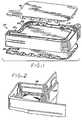
- FIGS. 1-17 illustrate a thermal ink-jet pen cartridge 50 embodying the present invention.
- the pen 50 comprises an external frame structure 60 which defines a closed band or loop defining the periphery of the pen 50.
- the pen structure 60 comprises two chemically dissimilar plastic members 78 and 68.
- the external plastic member 78 is molded from a relatively rigid engineering plastic such as a glass-filled modified polyphenylene oxide, such as the material marketed under the trademark "NORYL" by General Electric Company.
- An inner plastic member 68 is injection molded to the inner periphery of the external plastic member 78, and is fabricated of a plastic material suitable for attaching the ink reservoir membranes 64 and 66.
- a plastic suitable for the inner plastic member 68 is a polyolefin alloy or 10 percent glass-filled polyethylene.
- the frame 60 defines a generally rectilinear open volume region 110 and a snout region 75 protruding from one corner of region 110.
- the external plastic member 78 is molded to form a standpipe 93 with an interior opening or channel 94 formed therein.
- the standpipe channel 94 communicates with a TIJ printhead 76 secured across the external end of the snout opening 94. Ink flows through the standpipe channel 94 to supply the printhead 76 with ink. As drops of ink are forced outwardly through the printhead nozzles, ink flows through the standpipe 94 from the reservoir 62 via the fluid paths indicated generally by arrows 97 and 99 to replenish the ink supply available to the printhead 76.
- the inner plastic member 68 further includes a support rib 120 which extends across the throat of the snout region 75, separating the snout region from the main ink reservoir area 62.
- a generally rectangular chamber area 122 is formed by a surrounding structure of the inner member 68 extending between the rib 120 and the inner opening of the standpipe channel 94.
- First and second membranes 64 and 66 are attached to the inner plastic member 68 through heat staking, adhesives or other bonding processes, to form a leak-proof seal between the inner plastic member 68 and the membranes.
- the membranes 64 and 66 are formed of a material which is impermeable to the ink to be stored within the ink reservoir, and compatible with the plastic of material from which the inner plastic member 68 is fabricated.
- a preferred material for the membranes 64 and 66 is ethylene-vinyl acetate (EVA).
- EVA ethylene-vinyl acetate
- the ink delivery system includes a spring 74 which applies a separating force against two opposed piston plates 72A and 72B inside the ink reservoir to separate the membranes 64 and 66.
- the spring and piston elements maintain negative pressure on the ink in the reservoir to keep the ink from drooling from the printhead 76.
- atmospheric pressure on the membranes 64 and 66 result in compression of the spring with the plates 72A and 72B drawn toward each other.
- the membranes 64 and 66 extend over the standpipe region, and in this embodiment are heat staked along the edge regions 68A, 68B and 68C (FIG. 4) to maintain the sealing of the membranes along the periphery of the snout region 75.
- the membranes 64 and 66 are not sealed to the region of the rib 120.
- Standoffs 69A and 69B comprising the inner plastic member 68 hold the membranes off the area of rib 120, to ensure the membranes do not sag against the support rib structure and thereby close off the ink flow from the ink reservoir to the standpipe 93.
- An air check valve is provided in the fluid path between the printhead 76 and the ink reservoir 62, to prevent air bubbles from travelling from the printhead into the reservoir 62.
- the valve also serves the function of a filter to prevent particulate contaminates from flowing from the ink reservoir 62 to the printhead 76 and clogging the printhead nozzles.
- the valve includes two valve members 90, 92 one on each side of the frame.
- the valve members 90 and 92 each comprise, in this exemplary embodiment, a section of finely woven stainless steel mesh, the edges of which are attached to the inner plastic member.
- the mesh has a nominal passage dimension of 15 microns between adjacent mesh strands, and has a typical thickness of less than 0.127 cm (0.005 inches).
- each mesh member 90 and 92 is square, and covers an area of about one centimeter by one centimeter.
- a mesh marketed under the tradename RIGIMESH-J by Engle Tool and Die, Eugene, Oregon, is suitable for performing the function of the check valve.
- the mesh passage size is sufficiently small that, while ink may pass through the passages of the mesh, air bubbles under normal atmospheric pressure will not pass through the mesh passages which are wetted by the ink.
- the required air bubble pressure necessary to permit bubbles to pass through the mesh in this embodiment, about 30 inches of water, is well above that experienced by the pen under any typical storage, handling or operational conditions. As a result, the mesh serves the function of an air check valve for the pen.
- a second function fulfilled by the mesh valve is that of a particulate filter, preventing particles as small as 15 microns from passing through the mesh. It is known to use a mesh of this mesh opening size in a particulate filter in vented, foam-filled ink reservoirs, Such reservoirs have no need for an air check valve.
- FIGS. 4 and 5 illustrate the snout region 75 of the pen 50.
- FIG. 4 is a cross-section taken along line 4-4 of FIG. 3.
- FIG. 5 is a view of the snout without the covers and valve element 90 and 92 in place.
- the frame member 78 includes a pair of inwardly facing tabs 78A and 78B which provide support to the portion of inner frame member 68 molded around the inner periphery of the snout region 75.
- the tabs 78A and 78B also serve as coring features for molding of the inner member 68.
- the frame member 68 defines inner chamber 122, with a rectilinear frame portion extending around the periphery of the chamber.
- the frame portion is defined by side regions 68A-D.
- the width of member 68 defines the width of the chamber 122.
- the side regions 68A-D thus define a window into the chamber 122 on each cover-facing side of the member 68.
- Each side of the chamber 122 which extends in a perpendicular sense to the plane of the covers 70 and 80 is defined by the plastic comprising member 68.
- the printer in which the pen 50 is installed may include a priming station to apply a vacuum to the printhead to withdraw the air bubbles through the print-head, and draw ink from the reservoir to fill the standpipe opening and the chamber 122.
- a priming station to apply a vacuum to the printhead to withdraw the air bubbles through the print-head, and draw ink from the reservoir to fill the standpipe opening and the chamber 122.
- Such priming stations are known in the art.
- the frame member 68 is molded to define a thin lip 124 which protrudes from the side regions 68A-D and extends around the periphery of the frame portion. Such a lip is defined on each cover-facing side of the member 68; only lip 124 is visible in FIG. 5.
- the heated die member is positioned over the mesh member, and brought downwardly against the mesh member with force.
- the temperature of the die member is sufficient to soften or melt the plastic material defining the lip 124, so that some of the molten plastic flows into the adjacent interstices of the mesh.
- the mesh member firmly attached to the member 68 all around the periphery of the window into the chamber 122.
- FIGS. 6-9 illustrate the location and structure of the ink fill port 130 of pen 50.
- the fill port 130 is located in a flat surface 60A of the frame 60 adjacent the pen snout region 75.
- the ink reservoir 62 is filled with ink via the port 130, which is thereafter sealed off by insertion of a stainless steel ball 132.
- the external frame member 78 is molded to form an opening of circular cross-section, whose diameter transitions abruptly from a smaller diameter in the region 134 in which the ball 132 is captured, to a larger diameter in the region 136 adjacent the surface 60A.
- the ball 132 has a diameter of .187 inches (4.76 mm)
- the smaller diameter of the frame member 78 in the region 134 is .236 inches (6.0 mm)
- the larger diameter of the frame 78 in the region 136 is .283 inches (7.2 mm).
- the molten plastic flows through the opening formed for the ink fill port in the member 78 and around a mold pin inserted therein to form the fill port structure comprising the inner member 68.
- the molten plastic flows around the material forming the member 78 at region 134, providing a lining thereover.
- the inner member 68 thus formed defines the fill port opening 130 which communicates with the ink reservoir 62.
- the diameter of the fill port opening 130 tapers from a first diameter of the opening adjacent the surface to a second, smaller diameter at 138 adjacent the reservoir 62 which is substantially smaller than the diameter of the ball 132.
- the first diameter is .179 inches and the second diameter is .120 inches.
- the pen is held with the snout region 75 in an upright position as shown in FIG. 6.
- a needle is lowered through the fill port opening 130 down into the ink reservoir nearly touching the bottom of the reservoir. This is done so that the ink falls the shortest distance possible, as some inks will foam if they fall, which makes priming difficult later.
- the pen reservoir is then filled with ink through the ink fill needle by a pumping means to the point that the ink in the reservoir is nearly touching the inside of the ink fill hole. At this point the needle is drawn out of the pen and a ball 132 is placed over the ink fill opening 130.
- the ball fits tightly within the opening 138, as it must displace some of the plastic material surrounding the opening 130, due to its size relative to the opening size.
- the ball 130 is then pressed into the ink fill 130B by a pressing tool 140 (FIG. 9) such that it just touches the inner diameter at 138 at the bottom of the ink fill opening 130.
- the ink is contained in the pen reservoir; however, an air path exists from the top of the free surface of the ink through the printhead nozzles which must be removed to establish the initial pen back pressure.
- the air is pulled from the pen with the pen 50 tilted on a 30 degree angle such that the highest point is the snout region 75. This is done because the air will float to the highest point which then is the snout region, and thereby facilitating pulling the air from the pen by the primer.
- a suction head is then placed over the nozzle region of the thermal ink-jet head and vacuum pulled. As the vacuum removes air from the pen and the ink level will risen wet out the filter, and eventually make its way up to and through the printhead nozzles. This process has been characterized such that a known amount of ink will be pulled through the nozzles to establish the initial back pressure in the pen at -2,54 cm (-1 inch)of water.
- the top surface of the printhead is washed with clean water and an air knife to remove any excess ink from the priming process.
- the pen may be turned in any orientation with the ink remaining in the pen.
- FIGS. 10 and 11 show in isolation the outer plastic member 78 comprising the pen 50.
- the plastic member 78 presents an exterior flat surface 142, but that the inner side of member 78 presents several steps to increase the thickness of member 78, forming a plateau 146.
- a rib feature 144 is formed along the center of the member 78 extending from plateau 146, and includes undercut sides 144A and 144B. The rib 144 extends along part or nearly all of the sides of the frame member 78, as shown in FIG. 10.
- FIG. 12 is a side elevation view corresponding to FIG. 10, but showing the inner frame member 78 molded onto the outer frame member 78.
- the frame member 78 extends along the plateau 146, and covers the rib 144.
- the undercut sides of the rib provide a locking means for locking the member 68 onto the member 68.
- the member 68 has a thickness T (.059 inches) and a width W (.354 inches) in the area shown in FIG. 13.
- the sides 148 and 150 of the member 68 which extend generally perpendicular to the frame member 78 provide surfaces to which the ink reservoir membranes 64 and 66 may be attached.
- the material forming the inner member 68 has a shrink rate as it cools from the molten state. This material is molded inside the outer frame 78 and tends to shrink away from the frame 78 as it cools. To keep the inner plastic member 68 attached to the exterior frame member 78, it is molded onto the undercut features 144 which are molded as part of the member 78. As the material forming member 68 cools, it locks onto the external frame 78 by these features 144, thereby countering the forces of the material forming member 68 to pull away from the external frame 78 due to the shrinkage of that material.
- the locking rib 144 shown has a simple cross section which is easy to mold.
- a soft polyolefin alloy can be used as the material for member 68, as it adheres chemically to the surface of the NORYL material and has a shrink rate that is very low (about equal to the NORYL 6.35 mm/m (2.5 mills/inch) so that the forces created during the shrinking process are lower than, for example, pure polyethylene which is about 50.8 mm/m (20 mils/inch).
- FIGS. 14 and 15 show the structure of the members 68 and 78 in the snout region in further detail.
- the material of the inner member 68 flows over the ribs 78A and 78B, and covers the standpipe 93, locking onto the rib 93A.
- FIG. 16 is a cross-section taken along line 16-16 of FIG. 6. Elements defining the ink reservoir are visible here. Attachment of the spring bag membranes 64 and 66 to the opposed side surfaces 148 and 150 of the inner member 68 is illustrated. FIG. 17 in particular is an enlarged view illustrating the heat staked attachment of the membrane 66 to surface 148 of the inner frame member 68. Heat staking per se is well known in the plastics art.
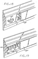
- FIGS. 18 and 19 illustrate two alternate embodiments of the locking features which may be formed on the inner surface of the frame member 78, instead of the undercut rib 144.
- FIG. 18 shows a frame member 78' which employs locking features 144', essentially small handle-like features with an opening 160 into which the molten plastic flows when the inner member 68' is molded.
- FIG. 19 shows a frame member 78'' which includes locking features 144'' which include rounded undercut openings 162 formed therein. The molten plastic flows into the undercut openings 162 when the inner member 68'' is molded.
- a method of molding the inner member 68 to the outer frame element 78 is described in the referenced application serial number 07/853,372. Briefly, the frame element 78 of modified polyphenylene oxide, i.e., a first molded material is fabricated in a plastic injection mold. This part 78 is referred to as the "first shot.” The first shot 78 is next inserted into a second mold where the second molded material is molded onto it. This "second shot” has a degree of shrinkage upon cooling.
- the inner frame member 68 can be made of a softer, more ductile material (such as a polyolefin alloy)than the engineering plastic of the exterior member 78, which also acts somewhat as a dampener in the event the pen is dropped. This tends to prevent cracking, membrane tears and other damage. Moreover, a soft, ductile material for the inner member 68, more like rubber than an engineering plastic, is not as prone to stress cracking.
- a polyethylene based material such as a polyolefin alloy to fabricate the inner member 68 has the further benefits of a low moisture transmission rate, thereby maintaining the ink contents of the reservoir against leakage or evaporation, and chemical compatibility with the chemicals constituting the inks used in the pen.
- the filters 90 and 92 can be readily attached to such materials for the member 68, in contrast to an engineering plastic, since the polyolefin based materials have a lower heat staking temperature, and the material readily wicks into the mesh of the filter, thereby providing a reliable joint between the inner member 68 and the air check valve/filter members 90 and 92.
- the core pin defining the standpipe chamber must engage the first shot material which forms element 78 and make a seal tight enough to keep the molten second shot material forming the inner frame member 68, which is under pressure, from entering.
- the engagement of the core pin on the inside of the standpipe 93 is a source of contamination, as the action of the engagement can cause particles to abrade off the wall of the first shot material and be left behind to later cause a contamination issue.
- the area of shut off and wiping of the core pin has been minimized by the design of the core pin 170 shown in FIG. 20.
- the second shot material forming member 68 is allowed to partially line the inside of the standpipe opening 94 to lessen the wiping action.
- FIG. 20 shows the two mold halves 174 and 176 which are brought together onto the frame structure 78 to define the mold cavity for the second shot molding of the inner frame member 68 at the snout region 75.
- the channel pin 172 fits across the mold halves.
- the mold cavity pin 170 is inserted into the standpipe opening, and its tip is received within a recession formed in the pin 172.
- the pin 170 is tapered to define an annular space above the shoulder 170A between the pin and the standpipe opening formed in the member 78.
- the pin 170 fits tightly within the standpipe opening below the shoulder 170A, forming a shutoff area 170B preventing the second shot material from flowing into the area 170B during molding.
- This pin configuration permits the second shot material to flow into the annular space, forming a lining covering the interior of the standpipe down to the shutoff region 170B.
- the surfaces 79A and 79B of the external member 78 also serve as shutoff surfaces which are contacted by surfaces of the mold halves, preventing the second shot material from flowing past the joint between the surfaces 79A and 79B and the mold halves.
- Another method to minimize the contamination problem is to automate the loading of the first-shot frame element 78 into the mold of the second shot machine.
- This automation uses a robot loader, which are conventional in the molding industry to place the frames into the second shot mold prior to molding.
- the frame can be loaded into the robot loader either by hand, by automated feeder systems, or a robot could be used to pick frames out of the first shot molding machine and place them into the second molding machine. All of these uses of automation allows for a better controlled environment which helps to keep the parts clean.
- This two material frame may also be produced by the two-shot molding technique, whereby one molding machine has the means for molding the first material, moving that just-molded shot into position for the barrel of the second material, then molding the second material to complete the part.
- two-shot molding processes are known in the art.
- the material with the higher melting temperature the engineering plastic of the external member 78
- the material with the lower melting point the polyolefin alloy or polyethylene based material
- this molding process may be reversed, with the higher melting temperature material molded over a lower melting temperature inner plastic member in an insert molding process.
- the interlock features between the frame members 68 and 78 will be formed on the first shot, i.e. the inner plastic member 68, with sufficient undercuts to lock the two materials together.
- the mold temperature needs to stay near or lower than the melting point of the low temperature first shot.
- the first shot will melt along the interface of the plastics.
- the molding conditions must be such that the first shot maintains its integrity, only being affected along the interface, and not getting washed out as the second shot is molded over the first shot.
- FIG. 21 illustrate such an insert molding process at the area of the standpipe of the pen 50.
- the member 68 is molded first in a first shot mold. Then, using surface of the member 68 to define some of the second shot mold surfaces, the external engineering plastic member 78 is molded over member 68.
- a core pin 180 and mold cap 182 define the inner standpipe opening and the top of the standpipe area.
- An outer ring of 184 of engineering plastic is formed over the first shot plastic 68, forming a compression ring to compress the lower temperature material of member 68 onto the inner standpipe formed by the second shot. As the second shot material cools, it compresses the first shot material against the second shot material at 186 defining the standpipe.
- FIG. 22 shows an alternate insert molding configuration for the standpipe, with the lower temperature material molded first.
- the second shot does not define a compression ring about the low temperature material surrounding the standpipe, so that the bonding between the two material is due solely to the chemical bond between the two materials which will be aided as the second shot material will melt the interface and help to cause a better bond than in the case of the molding the lower temperature material last.
- the second shot is cooling as it fills the mold and is not as hot in all areas along the joint as is possible in this case, due to the higher temperature of the second shot material and its heat capacity.
- the arrangement of FIG. 21 is superior to that of FIG. 22, as the former arrangement produces both a chemical and mechanical seal.
- Such an insert molding process of the high temperature material over the low temperature plastic material has several advantages.
- a main benefit is in the area of the standpipe.
- the core pin 180 that molds the standpipe opening to the TIJ printhead need only retract from the second shot after molding, and thus eliminates the abrasion problem described above.
- the core pin 182 in this case must retract, which can cause abrasion, but since the hole it is retracting from was formed by the very same core pin, the fit between the core pin and standpipe is very accurate and leads to less abrasion than in the case where the engineering plastic is the first shot material.
- Another molding process which can be used to fabricate the frame members 68 and 78 is a two-molding process with the higher temperature engineering plastic material molded over the lower temperature polyolefin.
- the first shot part must be carried inside of a core from which it tends to shrink away from and become loose.
- the first shot is molded onto a core which it shrinks onto tightly, and then the second shot is molded over the first shot, and it too shrinks tightly over the first shot.
- FIG. 23 illustrates an alternate embodiment of the snout end of the pen in its form prior to molding the inner plastic member 68 onto the engineering plastic frame member 78.
- the member 78''' defines an interior, upright fluid standpipe 98''' having an interior opening 94''' defined therein which extends through the standpipe to an opening formed in the exterior surface of the frame member 78'''. It is through this opening that the ink will flow from the reservoir to the printhead, which will be positioned at the snout end.
- FIG. 2 illustrates the open region 202 surrounding the upwardly extending fluid standpipe 98''' within the frame 78'''.
- a pair of spaced ribs 93A''' and 93B''' protrude from the exterior side of the standpipe 93'''.
- a strut 204 is formed across the throat of the snout 75''' region.
- the frame member 78''' is shown with the inner member 68''' molded to the inside surface of the frame member 78'''.
- the material forming the inner member 68''' has been molded around the periphery of the standpipe 98''', without covering the opening 94''', and provides a surface to which the spring bag film membranes may be staked.
Landscapes
- Engineering & Computer Science (AREA)
- Manufacturing & Machinery (AREA)
- Mechanical Engineering (AREA)
- Ink Jet (AREA)
- Injection Moulding Of Plastics Or The Like (AREA)
Claims (17)
- Cartouche d'encre pour imprimante (50) incluant un réservoir d'encre (62) comprenant :une structure de cadre (60) comprenant un élément de structure de cadre extérieur (78) fabriqué à partir d'un premier matériau plastique rigide et un élément de cadre intérieur (68) fabriqué à partir d'un second matériau plastique différent;de première et seconde membranes imperméables (64, 66) formées à partir d'un troisième matériau plastique différent, lesdites membranes étant reliées audit élément de cadre intérieur (68) pour former, avec ladite structure de cadre, ledit réservoir d'encre (62);
dans laquelle ledit second matériau plastique est compatible avec ledit troisième matériau plastique pour permettre une liaison sans fuites desdites membranes sur ledit élément de cadre intérieur; et
dans laquelle un passage de renouvellement d'encre (130) s'étend à travers ladite structure de cadre extérieure (78) et ledit élément de cadre intérieur (68) et en communication avec ledit réservoir d'encre, et
dans laquelle ledit passage est chemisé avec ledit second matériau plastique. - Cartouche d'encre selon la revendication 1, caractérisée, de plus, en ce que ledit second matériau plastique et ledit troisième matériau plastique sont compatibles, de sorte que lesdites membranes (64, 66) peuvent être scellées sur ledit élément de cadre intérieur (68) par application de chaleur et de pression.
- Cartouche d'encre selon la revendication 1, ou la revendication 2 caractérisée, de plus, en ce qu'une première ouverture est formée dans ladite structure de cadre extérieure (78) ledit second matériau plastique deladite structure de cadre intérieur (68) est disposé à travers ladite première ouverture et définissant ledit passage (130), ledit passage procurant un orifice pour distribuer l'encre dans ledit réservoir d'encre.
- Cartouche d'encre selon la revendication 3 caractérisée de plus par un moyen (132) pour rendre étanche ledit passage.
- Cartouche d'encre selon la revendication 4, dans laquelle ledit passage est caractérisé par une section transversale circulaire d'un certain diamètre de passage, et comprenant, de plus, un moyen (132) pour rendre étanche ledit passage, ledit moyen d'étanchéité comprenant un élément sphérique ayant un diamètre légèrement plus grand que ledit diamètre de passage, ledit élément sphérique étant introduit à force dans ledit passage (130) pour rendre étanche ledit passage.
- Cartouche d'encre selon l'une quelconque des revendications précédentes caractérisée, de plus, en ce que ledit élément de cadre extérieur (78) comprend une surface intérieure sur laquelle ledit élément de cadre intérieur (68) est fixé, ladite surface intérieure incluant un ou plusieurs motifs de verrouillage (144) formés dedans, et en ce que ledit élément de cadre intérieur (68) est formé par moulage par injection dudit second matériau plastique dans un état fondu, ledit second matériau plastique étant caractérisé par un certain taux de retrait lors du refroidissement de celui-ci, et dans laquelle pendant ledit moulage par injection ledit matériau fondu s'écoule autour dudit motif de verrouillage dudit élément de cadre extérieur, sur quoi ledit matériau fondu se refroidit et, de ce fait, verrouille ledit élément de cadre intérieur (68) audit élément de cadre extérieur (78) sur lesdits motifsde verrouillage (144).
- Cartouche d'encre selon la revendication 6 caractérisée, de plus, en ce que ledit motif de verrouillage (144) comprend une nervure en saillie s'étendant depuis ladite surface, ladite nervure définie par des côtés en contre-dépouille (144A 144B), dans laquelle pendant ledit moulage par injection, ledit second matériau plastique fondu s'écoule autour de ladite nervure contre lesdits côtés en contredépouille.
- Cartouche d'encre selon la revendication 6 caractérisée, de plus, en ce que ledit motif de verrouillage (144) comprend un élément en forme de poignée (144') ayant une ouverture de poignée (160) formée dedans, dans laquelle pendant ledit moulage par injection, ledit matériau plastique fondu s'écoule autour de ladite caractéristique en forme de poignée dans ladite ouverture de poignée pour verrouiller dessus ledit élément en matière plastique extérieur (78).
- Cartouche d'encre selon l'une quelconque des revendications précédentes caractérisée, de plus, en ce que ledit élément de cadre extérieur (78) définit un anneau pratiquement fermé autour dudit réservoir d'encre (62), ledit anneau présentant un côté faisant face vers l'intérieur, ladite surface intérieure s'étendant autour d'au moins une partie dudit côté faisant face vers l'intérieur.
- Cartouche d'encre selon l'une quelconque des revendications précédentes caractérisée, de plus, en ce que ledit élément de cadre intérieur (68) comprend des première et seconde surfaces opposées (148) sur lesquelles lesdites première et seconde membranes (64, 66) sont reliées.
- Cartouche d'encre selon l'une quelconque des revendications 1 à 5, caractérisée, de plus, par des moyens de fixation dudit élément de cadre extérieur (78) et dudit élément de cadre intérieur (68) ensemble, comprenant un premier jeu d'éléments (144) formés sur une surface intérieure dudit élément de cadre extérieur et un second jeu de motifs formés sur une surface dudit élément de cadre intérieur (68) à fixer sur ledit élément de cadre extérieur, dans laquelle les motifs dudit premier jeu se verrouillent mécaniquement avec les motifs dudit second jeu.
- Cartouche d'encre selon la revendication 11 caractérisée, de plus, en ce que ledit élément extérieur (78) et formé par moulage par injection dudit premier matériau dans un état fondu, ledit premier matériau étant caractérisé par un certain faux de retrait lors du refroidissement de celui-ci, et dans laquelle pendant ledit moulage par injection ledit premier matériau fondu s'écoule autour dudit second jeu de motifs dudit élément intérieur, sur quoi ledit matériau fondu se refroidit, formant ledit premier jeu de motifs qui est verrouillé mutuellement avec ledit second jeu de motifs.
- Procédé pour distribuer de l'encre dans un réservoir d'encre d'une cartouche à plume d'imprimante, comprenant une séquence des étapes suivantes :création d'une cartouche à plume d'imprimante incluant une structure de cadre (60) comprenant un élément de structure de cadre extérieur (78) fabriqué à partir d'un premier matériau plastique rigide, et un élément de cadre intérieur (68) fabriqué à partir d'un second matériau plastique différent, ledit élément intérieur chemisant une surface intérieure dudit élément de cadre extérieur, des première et seconde membranes imperméables (64, 66) formées à partir d'un troisième matériau plastique lié audit élément de cadre intérieur pour former avec ledit élément de cadre intérieur, un réservoir d'encre (62) pour contenir une alimentation d'encre, et un orifice de renouvellement d'encre (130) comprenant un passage défini à travers ledit élément de cadre extérieur, ledit passage chemisé avec ledit second matériau dudit élément intérieur et communiquant avec l'intérieur dudit réservoir; etinjection de l'encre dans ledit réservoir d'encre à partir d'une alimentation d'encre à travers ledit orifice.
- Procédé selon la revendication 13 comprenant, de plus, l'étape de positionnement deladite plume de sorte que ledit orifice (130) fait face vers le haut, et dans lequel ladite étape d'injection de l'encre dans ledit réservoir comprend les étapes d'insertion d'un tube creux à travers ledit passage dans ledit réservoir (62), et l'injection d'un écoulement d'encre à travers ledit tube dans ledit réservoir.
- Procédé selon la revendication 14, dans lequel ledit tube est inséré dans pratiquement toute la hauteur dudit réservoir pour réduire les éclaboussures et la formation de mousse de ladite encre pendant ladite étape de remplissage.
- Procédé selon l'une quelconque des revendications 13, 14 ou 15 comprenant, de plus, l'étape de fermeture hermétique dudit orifice après injection deladite encre dans ledit réservoir.
- Procédé selon la revendication 16 dans lequel ledit passage (130) a une section transversale circulaire d'un premier diamètre, et ledit élément d'étanchéité (132) a une section transversale circulaire d'un second diamètre et dans lequel ledit second diamètre est plus grand que ledit premier diamètre.
Applications Claiming Priority (2)
| Application Number | Priority Date | Filing Date | Title |
|---|---|---|---|
| US994807 | 1992-12-22 | ||
| US07/994,807 US5515092A (en) | 1992-03-18 | 1992-12-22 | Two material frame having dissimilar properties for thermal ink-jet cartridge |
Publications (2)
| Publication Number | Publication Date |
|---|---|
| EP0604712A1 EP0604712A1 (fr) | 1994-07-06 |
| EP0604712B1 true EP0604712B1 (fr) | 1998-11-04 |
Family
ID=25541076
Family Applications (1)
| Application Number | Title | Priority Date | Filing Date |
|---|---|---|---|
| EP93114954A Expired - Lifetime EP0604712B1 (fr) | 1992-12-22 | 1993-09-16 | Cadre en deux matériaux avec propriétés différentes pour une tête d'impression thermique à jet d'encre |
Country Status (4)
| Country | Link |
|---|---|
| US (3) | US5515092A (fr) |
| EP (1) | EP0604712B1 (fr) |
| JP (1) | JP3310436B2 (fr) |
| DE (1) | DE69321927T2 (fr) |
Families Citing this family (59)
| Publication number | Priority date | Publication date | Assignee | Title |
|---|---|---|---|---|
| US5757406A (en) * | 1992-08-12 | 1998-05-26 | Hewlett-Packard Company | Negative pressure ink delivery system |
| US5748216A (en) * | 1991-06-19 | 1998-05-05 | Hewlett-Packard Company | Inkjet print cartridge having valve connectable to an external ink reservoir for recharging the print cartridge |
| US5963238A (en) * | 1991-06-19 | 1999-10-05 | Hewlett-Packard Company | Intermittent refilling of print cartridge installed in an inkjet printer |
| US5777648A (en) * | 1991-06-19 | 1998-07-07 | Hewlett-Packard Company | Inkjet print cartridge having an ink fill port for initial filling and a recharge port with recloseable seal for recharging the print cartridge with ink |
| US5852458A (en) * | 1991-08-27 | 1998-12-22 | Hewlett-Packard Company | Inkjet print cartridge having a first inlet port for initial filling and a second inlet port for ink replenishment without removing the print cartridge from the printer |
| US5515092A (en) * | 1992-03-18 | 1996-05-07 | Hewlett-Packard Company | Two material frame having dissimilar properties for thermal ink-jet cartridge |
| US5984463A (en) * | 1992-03-18 | 1999-11-16 | Hewlett-Packard Company | Two material frame having dissimilar properties for thermal ink-jet cartridge |
| US5464578A (en) * | 1992-03-18 | 1995-11-07 | Hewlett-Packard Company | Method of making a compact fluid coupler for thermal inkjet print cartridge ink reservoir |
| US5675367A (en) * | 1992-12-23 | 1997-10-07 | Hewlett-Packard Company | Inkjet print cartridge having handle which incorporates an ink fill port |
| US6000791A (en) * | 1992-12-23 | 1999-12-14 | Hewlett-Packard Company | Printer having a removable print cartridge with handle incorporating an ink inlet value |
| US5574489A (en) * | 1994-03-30 | 1996-11-12 | Hewlett-Packard Company | Ink cartridge system for ink-jet printer |
| US5673073A (en) * | 1994-09-29 | 1997-09-30 | Hewlett-Packard Company | Syringe for filling print cartridge and establishing correct back pressure |
| US5751320A (en) * | 1994-09-29 | 1998-05-12 | Hewlett-Packard Company | Ink recharger for inkjet print cartridge having sliding valve connectable to print cartridge |
| US5686949A (en) * | 1994-10-04 | 1997-11-11 | Hewlett-Packard Company | Compliant headland design for thermal ink-jet pen |
| US5751323A (en) * | 1994-10-04 | 1998-05-12 | Hewlett-Packard Company | Adhesiveless printhead attachment for ink-jet pen |
| US5896153A (en) * | 1994-10-04 | 1999-04-20 | Hewlett-Packard Company | Leak resistant two-material frame for ink-jet print cartridge |
| JP3251845B2 (ja) | 1995-04-17 | 2002-01-28 | キヤノン株式会社 | 負圧を与える液体収納容器、該容器の製造方法、該容器とインクジェット記録ヘッドとを一体化したインクジェットカートリッジ及びインクジェット記録装置 |
| DE29507743U1 (de) * | 1995-05-10 | 1996-09-12 | Pelikan Produktions Ag, Egg | Druckkopf für einen Ink-Jet-Printer |
| USD419593S (en) * | 1997-12-25 | 2000-01-25 | Canon Kabushiki Kaisha | Ink tank for printer |
| US5992992A (en) * | 1998-06-11 | 1999-11-30 | Lexmark International, Inc. | Pressure control device for an ink jet printer |
| USD430897S (en) * | 1999-06-11 | 2000-09-12 | Lexmark International, Inc. | Ink cartridge for printer |
| US6485979B1 (en) | 1999-08-05 | 2002-11-26 | 3M Innovative Properties Company | Electronic system for tracking and monitoring articles to be sterilized and associated method |
| US6264313B1 (en) | 1999-09-10 | 2001-07-24 | Nypro, Inc. | Fluid delivery manifold and method of manufacturing the same |
| AU2005200944B2 (en) * | 1999-12-09 | 2006-03-30 | Memjet Technology Limited | Printhead Assembly Having Two-Shot Ink Supply Molding |
| US7182441B2 (en) * | 1999-12-09 | 2007-02-27 | Silverbrook Research Pty Ltd | Printhead module |
| AU767236B2 (en) * | 1999-12-09 | 2003-11-06 | Memjet Technology Limited | An ink supply device for a four color modular printhead |
| AUPQ455999A0 (en) * | 1999-12-09 | 2000-01-06 | Silverbrook Research Pty Ltd | Memjet four color modular print head packaging |
| US7677698B2 (en) * | 1999-12-09 | 2010-03-16 | Silverbrook Research Pty Ltd | Modular printhead assembly with reservoir mounted printhead modules |
| USD441787S1 (en) | 2000-02-08 | 2001-05-08 | Lexmark International, Inc. | Ink cartridge for printer |
| USD437611S1 (en) | 2000-02-08 | 2001-02-13 | Lexmark International, Inc. | Ink cartridge for printer |
| US6260961B1 (en) | 2000-03-02 | 2001-07-17 | Hewlett-Packard Company | Unitary one-piece body structure for ink-jet cartridge |
| US6250751B1 (en) | 2000-03-28 | 2001-06-26 | Lexmark International, Inc. | Ink jet printer cartridge manufacturing method and apparatus |
| US6823624B2 (en) | 2001-07-17 | 2004-11-30 | S.I.T., Inc. | Plastic article with protuberance |
| US6625394B2 (en) | 2001-12-21 | 2003-09-23 | Eastman Kodak Company | Two-shot molded seal integrity indicator, underwater camera, and method |
| US6574429B1 (en) | 2001-12-21 | 2003-06-03 | Eastman Kodak Company | Underwater camera having viewports bearing on viewfinder tunnel of frame |
| US6636697B2 (en) | 2001-12-21 | 2003-10-21 | Eastman Kodak Company | Depressurized underwater one-time-use camera with seal integrity indicator and method |
| US6636695B2 (en) | 2001-12-21 | 2003-10-21 | Eastman Kodak Company | Dual action shutter release with thumbwheel brake and methods |
| US6618555B2 (en) | 2001-12-21 | 2003-09-09 | Eastman Kodak Company | Underwater one-time-use camera having camera frame assembly retained in front housing part at unloading |
| US6574435B1 (en) | 2001-12-21 | 2003-06-03 | Eastman Kodak Company | Underwater camera housing having sealed pivotable shutter actuator and method |
| US6523579B1 (en) | 2002-02-06 | 2003-02-25 | Hewlett-Packard Company | Method of manufacturing an ink jet print cartridge and ink jet print cartridge manufactured using the same |
| US6702435B2 (en) * | 2002-07-18 | 2004-03-09 | Eastman Kodak Company | Ink cartridge having ink identifier oriented to provide ink identification |
| KR100453057B1 (ko) | 2002-09-06 | 2004-10-15 | 삼성전자주식회사 | 잉크젯 프린터에 있어서 인쇄제어방법 |
| US6883907B2 (en) * | 2002-10-24 | 2005-04-26 | Hewlett-Packard Development Company, L.P. | Ink cartridge and expansible bladder for an ink cartridge |
| US6966639B2 (en) * | 2003-01-28 | 2005-11-22 | Hewlett-Packard Development Company, L.P. | Ink cartridge and air management system for an ink cartridge |
| JP2004268575A (ja) * | 2003-02-19 | 2004-09-30 | Seiko Epson Corp | 液体貯留手段及び液体噴射装置 |
| US7296204B2 (en) * | 2003-05-30 | 2007-11-13 | Wegener Communications, Inc. | Error correction apparatus and method |
| US6817707B1 (en) | 2003-06-18 | 2004-11-16 | Lexmark International, Inc. | Pressure controlled ink jet printhead assembly |
| US7384133B2 (en) * | 2003-08-08 | 2008-06-10 | Seiko Epson Corporation | Liquid container capable of maintaining airtightness |
| US7159974B2 (en) * | 2003-10-06 | 2007-01-09 | Lexmark International, Inc. | Semipermeable membrane for an ink reservoir and method of attaching the same |
| CN2726881Y (zh) * | 2004-09-06 | 2005-09-21 | 聂瑞权 | 喷墨打印机墨盒 |
| US7775645B2 (en) * | 2005-09-29 | 2010-08-17 | Brother Kogyo Kabushiki Kaisha | Methods of forming cartridges, such as ink cartridges |
| US8025376B2 (en) * | 2005-09-29 | 2011-09-27 | Brother Kogyo Kabushiki Kaisha | Ink cartridges |
| US20070146446A1 (en) * | 2005-12-22 | 2007-06-28 | Buchanan Jeffery J | Ink jet cartridge comprising a porous core and methods for manufacturing the same |
| US20070287983A1 (en) * | 2006-06-07 | 2007-12-13 | Richard Worthington Lodge | Absorbent article having an anchored core assembly |
| KR100916920B1 (ko) | 2008-02-01 | 2009-09-09 | 삼성모바일디스플레이주식회사 | 잉크 카트리지 |
| JP4852562B2 (ja) * | 2008-03-24 | 2012-01-11 | セイコーエプソン株式会社 | 液体収容体 |
| US8091993B2 (en) * | 2008-05-22 | 2012-01-10 | Videojet Technologies Inc. | Ink containment system and ink level sensing system for an inkjet cartridge |
| US8272704B2 (en) | 2008-05-22 | 2012-09-25 | Zipher Limited | Ink containment system and ink level sensing system for an inkjet cartridge |
| JP5565029B2 (ja) * | 2010-03-29 | 2014-08-06 | セイコーエプソン株式会社 | 液体容器および液体消費装置 |
Family Cites Families (11)
| Publication number | Priority date | Publication date | Assignee | Title |
|---|---|---|---|---|
| US2609570A (en) * | 1951-01-22 | 1952-09-09 | Elmer L Danielson | Method for forming a multipart plastic article |
| DE2704735C2 (de) * | 1977-02-04 | 1982-08-05 | Siemens AG, 1000 Berlin und 8000 München | Auslaufsicherer Tintenvorratsbehälter |
| US4385025A (en) * | 1979-10-22 | 1983-05-24 | Barry Wright Corporation | Method of coinjection molding of thermoplastic and thermoplastic elastomer |
| US4512720A (en) * | 1983-04-12 | 1985-04-23 | Barry Wright Corporation | Pump impellers and manufacture thereof by co-injection molding |
| CA2019290A1 (fr) * | 1990-01-12 | 1991-07-12 | Bruce Cowger | Compensateur de pression pour plumes reservoir |
| US5047790A (en) * | 1990-01-12 | 1991-09-10 | Hewlett-Packard Company | Controlled capillary ink containment for ink-jet pens |
| US5359353A (en) * | 1991-06-19 | 1994-10-25 | Hewlett-Packard Company | Spring-bag printer ink cartridge with volume indicator |
| US5280300A (en) * | 1991-08-27 | 1994-01-18 | Hewlett-Packard Company | Method and apparatus for replenishing an ink cartridge |
| US5515092A (en) * | 1992-03-18 | 1996-05-07 | Hewlett-Packard Company | Two material frame having dissimilar properties for thermal ink-jet cartridge |
| US5464578A (en) * | 1992-03-18 | 1995-11-07 | Hewlett-Packard Company | Method of making a compact fluid coupler for thermal inkjet print cartridge ink reservoir |
| US5325119A (en) * | 1992-08-12 | 1994-06-28 | Hewlett-Packard Company | Variable rate spring ink pressure regulator for a thermal ink jet printer |
-
1992
- 1992-12-22 US US07/994,807 patent/US5515092A/en not_active Expired - Lifetime
-
1993
- 1993-09-16 DE DE69321927T patent/DE69321927T2/de not_active Expired - Lifetime
- 1993-09-16 EP EP93114954A patent/EP0604712B1/fr not_active Expired - Lifetime
- 1993-12-21 JP JP34544393A patent/JP3310436B2/ja not_active Expired - Lifetime
-
1995
- 1995-06-07 US US08/483,612 patent/US5874978A/en not_active Expired - Lifetime
-
1996
- 1996-05-01 US US08/641,408 patent/US5737002A/en not_active Expired - Lifetime
Also Published As
| Publication number | Publication date |
|---|---|
| DE69321927D1 (de) | 1998-12-10 |
| US5737002A (en) | 1998-04-07 |
| US5874978A (en) | 1999-02-23 |
| US5515092A (en) | 1996-05-07 |
| JP3310436B2 (ja) | 2002-08-05 |
| DE69321927T2 (de) | 1999-06-02 |
| JPH06293139A (ja) | 1994-10-21 |
| EP0604712A1 (fr) | 1994-07-06 |
Similar Documents
| Publication | Publication Date | Title |
|---|---|---|
| EP0604712B1 (fr) | Cadre en deux matériaux avec propriétés différentes pour une tête d'impression thermique à jet d'encre | |
| US5594483A (en) | Ink-jet cartridge with ink filtration | |
| KR100235281B1 (ko) | 잉크제트 인쇄 시스템과 잉크제트 프린트 카트리지의 충전 및 보충방법 | |
| KR100233977B1 (ko) | 잉크보충 시스템과 잉크제트 프린트 카트리지의 보충방법 및 프린트 카트리지 보충 시스템 이용방법 | |
| EP0795409B1 (fr) | Systèmes d'impression | |
| CN100411873C (zh) | 墨盒 | |
| US6003984A (en) | Ink-jet swath printer with auxiliary ink reservoir | |
| KR100254763B1 (ko) | 인쇄시스템과프린트카트리지재충전방법 | |
| CA2093981C (fr) | Reservoir d'encre repliable et cartouche d'encre d'imprimante | |
| EP2326510B1 (fr) | Réservoir d'encre pour imprimantes à jet d'encre | |
| US7025448B2 (en) | Fluid interconnect in a replaceable ink reservoir for pigmented ink | |
| KR100235283B1 (ko) | 잉크제트 인쇄 시스템과 잉크제트 프린트 카트리지 충전방법 | |
| US6916088B2 (en) | Ink container configured to establish reliable fluidic connection to a receiving station | |
| EP0841174A2 (fr) | Cadre en deux matériaux avec propriétés différentes pour cartouche d'impression thermique à jet d'encre | |
| EP0745481A2 (fr) | Imprimante à jet d'encre avec réservoir auxiliaire | |
| JP3267488B2 (ja) | インク記録ヘッド用インクタンクのインク再充填装置およびインク再充填方法 | |
| JP3613346B2 (ja) | インクカートリッジへのインクの充填方法 | |
| JPH11309870A (ja) | ヘッドカートリッジ、インクジェットカートリッジ、インクジェット記録装置、およびヘッドカートリッジと液体供給容器との結合方法 | |
| CN100548694C (zh) | 用于喷墨记录装置的墨盒 | |
| JPH10315497A (ja) | インクカートリッジ | |
| KR0152424B1 (ko) | 액체용기, 액체용기유닛, 잉크제트카트리지, 잉크제트헤드 및 프린터 | |
| JPH0872257A (ja) | インク記録ヘッド用インクタンクのインク再充填方法および再充填装置 | |
| JPH0781083A (ja) | インクカートリッジ及び該カートリッジを有するインクジェット記録ユニット、該記録ユニットを有する記録装置 | |
| HK1058335B (en) | Ink container configured to establish reliable fluidic connection to a receiving station |
Legal Events
| Date | Code | Title | Description |
|---|---|---|---|
| PUAI | Public reference made under article 153(3) epc to a published international application that has entered the european phase |
Free format text: ORIGINAL CODE: 0009012 |
|
| AK | Designated contracting states |
Kind code of ref document: A1 Designated state(s): DE FR GB IT |
|
| 17P | Request for examination filed |
Effective date: 19941206 |
|
| 17Q | First examination report despatched |
Effective date: 19951206 |
|
| GRAG | Despatch of communication of intention to grant |
Free format text: ORIGINAL CODE: EPIDOS AGRA |
|
| GRAG | Despatch of communication of intention to grant |
Free format text: ORIGINAL CODE: EPIDOS AGRA |
|
| GRAH | Despatch of communication of intention to grant a patent |
Free format text: ORIGINAL CODE: EPIDOS IGRA |
|
| GRAH | Despatch of communication of intention to grant a patent |
Free format text: ORIGINAL CODE: EPIDOS IGRA |
|
| GRAA | (expected) grant |
Free format text: ORIGINAL CODE: 0009210 |
|
| AK | Designated contracting states |
Kind code of ref document: B1 Designated state(s): DE FR GB IT |
|
| REF | Corresponds to: |
Ref document number: 69321927 Country of ref document: DE Date of ref document: 19981210 |
|
| ET | Fr: translation filed | ||
| ITF | It: translation for a ep patent filed | ||
| PLBE | No opposition filed within time limit |
Free format text: ORIGINAL CODE: 0009261 |
|
| 26N | No opposition filed | ||
| REG | Reference to a national code |
Ref country code: GB Ref legal event code: 732E |
|
| REG | Reference to a national code |
Ref country code: FR Ref legal event code: TP |
|
| REG | Reference to a national code |
Ref country code: GB Ref legal event code: IF02 |
|
| REG | Reference to a national code |
Ref country code: GB Ref legal event code: 732E Free format text: REGISTERED BETWEEN 20120329 AND 20120404 |
|
| PGFP | Annual fee paid to national office [announced via postgrant information from national office to epo] |
Ref country code: GB Payment date: 20120925 Year of fee payment: 20 |
|
| PGFP | Annual fee paid to national office [announced via postgrant information from national office to epo] |
Ref country code: IT Payment date: 20120924 Year of fee payment: 20 Ref country code: FR Payment date: 20121001 Year of fee payment: 20 |
|
| PGFP | Annual fee paid to national office [announced via postgrant information from national office to epo] |
Ref country code: DE Payment date: 20120927 Year of fee payment: 20 |
|
| REG | Reference to a national code |
Ref country code: DE Ref legal event code: R071 Ref document number: 69321927 Country of ref document: DE |
|
| REG | Reference to a national code |
Ref country code: GB Ref legal event code: PE20 Expiry date: 20130915 |
|
| PG25 | Lapsed in a contracting state [announced via postgrant information from national office to epo] |
Ref country code: DE Free format text: LAPSE BECAUSE OF EXPIRATION OF PROTECTION Effective date: 20130917 |
|
| PG25 | Lapsed in a contracting state [announced via postgrant information from national office to epo] |
Ref country code: GB Free format text: LAPSE BECAUSE OF EXPIRATION OF PROTECTION Effective date: 20130915 |