EP0604714A1 - Outil de support pour bouchon obturateur de conduite de vapeur - Google Patents
Outil de support pour bouchon obturateur de conduite de vapeur Download PDFInfo
- Publication number
- EP0604714A1 EP0604714A1 EP93115549A EP93115549A EP0604714A1 EP 0604714 A1 EP0604714 A1 EP 0604714A1 EP 93115549 A EP93115549 A EP 93115549A EP 93115549 A EP93115549 A EP 93115549A EP 0604714 A1 EP0604714 A1 EP 0604714A1
- Authority
- EP
- European Patent Office
- Prior art keywords
- steam line
- support tool
- plug
- line plug
- vessel
- Prior art date
- Legal status (The legal status is an assumption and is not a legal conclusion. Google has not performed a legal analysis and makes no representation as to the accuracy of the status listed.)
- Withdrawn
Links
- 238000012360 testing method Methods 0.000 claims abstract description 16
- 238000009434 installation Methods 0.000 claims abstract description 11
- XLYOFNOQVPJJNP-UHFFFAOYSA-N water Substances O XLYOFNOQVPJJNP-UHFFFAOYSA-N 0.000 claims abstract description 10
- 238000009835 boiling Methods 0.000 claims abstract description 6
- 239000002184 metal Substances 0.000 claims description 9
- 238000012423 maintenance Methods 0.000 claims description 7
- 229910001220 stainless steel Inorganic materials 0.000 claims description 5
- 239000010935 stainless steel Substances 0.000 claims description 5
- 238000007689 inspection Methods 0.000 claims description 4
- 238000000034 method Methods 0.000 claims 7
- 238000010276 construction Methods 0.000 description 2
- 229910000831 Steel Inorganic materials 0.000 description 1
- 239000011358 absorbing material Substances 0.000 description 1
- 239000003758 nuclear fuel Substances 0.000 description 1
- 239000010959 steel Substances 0.000 description 1
Images

Classifications
-
- G—PHYSICS
- G21—NUCLEAR PHYSICS; NUCLEAR ENGINEERING
- G21C—NUCLEAR REACTORS
- G21C13/00—Pressure vessels; Containment vessels; Containment in general
- G21C13/02—Details
- G21C13/06—Sealing-plugs
- G21C13/067—Sealing-plugs for tubes, e.g. standpipes; Locking devices for plugs
-
- G—PHYSICS
- G21—NUCLEAR PHYSICS; NUCLEAR ENGINEERING
- G21C—NUCLEAR REACTORS
- G21C13/00—Pressure vessels; Containment vessels; Containment in general
- G21C13/02—Details
- G21C13/028—Seals, e.g. for pressure vessels or containment vessels
-
- Y—GENERAL TAGGING OF NEW TECHNOLOGICAL DEVELOPMENTS; GENERAL TAGGING OF CROSS-SECTIONAL TECHNOLOGIES SPANNING OVER SEVERAL SECTIONS OF THE IPC; TECHNICAL SUBJECTS COVERED BY FORMER USPC CROSS-REFERENCE ART COLLECTIONS [XRACs] AND DIGESTS
- Y02—TECHNOLOGIES OR APPLICATIONS FOR MITIGATION OR ADAPTATION AGAINST CLIMATE CHANGE
- Y02E—REDUCTION OF GREENHOUSE GAS [GHG] EMISSIONS, RELATED TO ENERGY GENERATION, TRANSMISSION OR DISTRIBUTION
- Y02E30/00—Energy generation of nuclear origin
- Y02E30/30—Nuclear fission reactors
Definitions
- This invention relates to a support tool and, more particularly, to a support tool for maintaining steam line plugs supported in the steam line nozzles during the local leak rate test of boiling water reactors. Still more particularly, this invention relates to a steam line plug installation and support tool.
- Steam line plugs are installed in the steam line nozzles of boiling water reactors for inspection and maintenance of the steam line system of the reactor.
- the plugs are of two types.
- One type of plug is only used to prevent the steam line from being filled with water.
- a positive head of water on the reactor side of the plug keeps the plug inserted in the steam line nozzle while the line is drained.
- the plug may contain a vent valve operated remotely to allow the steam lines to refill after maintenance.
- This type of plug cannot withstand the back pressure which results from the local leak rate testing of the main steam valve closest to the plug. A force of approximately 50 psi will force the plug from the steam line nozzle.
- Another type of plug has been developed to withstand the back pressure from the local leak rate testing of the main steam valve closest to the plug.
- this plug In order to absorb the load resulting from the back pressure and remain in place in the steam line, however, this plug must incorporate an elaborate expansion device.
- the expansion device may include hydraulically expanded rings to lock the steam line plug against back pressure. It is, thus, a problem in the prior art to provide a steam line plug which is of simple design and does not require elaborate expansion devices, and yet is able to withstand the local leak rate test pressure and remain in place in the steam line.
- the steam line plug may be attached
- FIGs. 1a and 1b Illustrated in Figs. 1a and 1b is the steam line plug support tool 10 of the present invention.
- a steam line plug 15 is shown inserted in a steam line nozzle 16 in a wall 20 of a reactor vessel 5.
- a shroud, an internal vessel for holding the reactor fuel in the reactor vessel, is shown at 30.
- a feedwater sparger for the vessel is shown at 35.
- the plug 15 is inserted in nozzle 16 for inspection and maintenance of a steam line 17.
- the plug 15 allows the reactor vessel 5 to remain filled with water while the steam line 17 is drained and maintenance tests are conducted on the line.
- the plug 15 prevents the steam line 17 from being filled with water, and, with use of the support tool 10 of the present invention, will withstand back pressure in the steam line resulting from, for example, a local leak rate test.
- the plug 15 may be any conventional steam plug of complicated or simple design, it is preferably of simple construction. Further, the plug may contain a vent valve operated remotely to allow the steam lines to refill after maintenance.
- the support tool 10 consists of a beam 11 which when installed is supported at an upper end 12 from a reactor pressure vessel flange 22 at the top of the vessel wall 20 or a vessel stud 26 by means of a clamp 25.
- the beam 11 is supported at a lower end 13 by edge 31 of the shroud 30 of the reactor vessel 5.
- a plate 14 is affixed to plug 15 by means of a connection piece 6.
- the connection piece 6 is fixed to the support tool at a location along the support tool 10 to coincide with the position of the steam line plug 15 to make surface contact between the tool and the plug 15.
- the plate 14 presses the plug 15 towards the nozzle 16 with a force that corresponds, at least, to the maximum local leak rate back pressure.
- the support tool 10 thereby, supports plug 15 during the local leak rate test so that the plug 15 remains in the nozzle 16 during the test.
- the length of the beam 11 of the support tool 10 will vary depending on the upper support point of the tool 10. When the beam 11 is fitted to a flange 22 or stud 26 of the reactor pressure vessel wall 20, it should be of a length to fit from the flange 22 or the stud 26 down to the shroud 30, preferably, approximately 30 feet.
- the support tool 10 may be constructed from any rigid force absorbing material such as any metal, preferably steel, and still more preferably stainless steel.
- the support tool 10 can be divided into two sections for use in plants without sufficient height between the refueling floor and the overhead crane to permit installation of the support tool in one piece or for convenience of storage.
- the lower section 13 of beam 11 may be attached to beam 11 at the point shown at 27 by any suitable means such as a hinge or bolt, or may be telescopically connected as shown in Figs. 1a and 1b.
- a locking mechanism may be used to lock the beam 11 in the outstretched position shown in Fig. 1 such as a pin for use with a hinge connection.
- the lower section 13 When telescopically connected, the lower section 13 may be retracted into the upper section 12 of beam 11 to create a compact design.
- the lower section 13 may be pulled out from the upper section 12 and automatically locked into place.
- the upper and lower sections may be of any length relative to each other which facilitates installation of the beam while still providing support.
- the ratio of the length of the upper section to the lower section could be 1:1 so that if the entire beam were thirty feet the upper and lower section would each be fifteen feet.
- the ratio between the length of the upper section to the lower section is 3:2 such that if the entire beam were thirty feet the upper section would be eighteen feet and the lower section would be twelve feet.
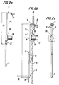
- FIGs. 2a-2c Another embodiment of the present invention is shown in Figs. 2a-2c.
- a plug 30 is attached to a sliding plate 24 which is slidably mounted on the beam 11 of support tool 10.
- the steam line plug 30 is affixed to the plate 24 on the support tool 10 by any suitable means such as bolts or screws.
- the plate 24 acts as a sliding guide to guide the tool 10 and its position along the tool 10 may be adjusted.
- Fig. 2a illustrates the tool 10 and the plug 30 in a first position with the plug 30 centered in front of the nozzle 16 of the steam line 17 ready for installation into the nozzle 16.
- the tool 10 and the plug 30 are moved into the reactor vessel and steam line 17 from the first position illustrated in Fig. 2a to a second position illustrated in Fig. 2b.
- the tool 10 supports the plug 30 in the nozzle 16 with the upper end 12 hanging from the flange 22 or stud 26 and the lower end 13 supported by the edge 31 of the shroud 30.
- the plug 30 fits in the nozzle 16 and the tool 10 is then lowered from the first position to the second supporting position.
- the support tool 10 As the support tool 10 is lowered, it slides relative to plug 30 inside the sliding device 24 thereby allowing the tool to adjust itself vertically in relation to the plug. The tool, thus, compensates for differences in height between the nozzle and the vessel flange.
- the tool 10 is then clamped to the reactor pressure vessel flange or stud as described in connection with Figs. 1a and 1b. Because the support tool and the plug are combined, the total installation and clamping time is advantageously reduced. In addition, the embodiment of the invention shown in Figs. 2a-2c is especially advantageous for use in replacing old steam line plugs with new ones.
- the support tool 10 can be installed and used during the local leak rate test period. Further, if testing conditions permit, the support tool 10 can be moved between steam line plugs.
- the tool 10 is designed to be used underwater, but, as the plugs are installed dry or wet, it may also be used dry.
- the present invention provides a simple, low cost device to support and install a steam line plug in steam line nozzles.
- the support tool of the present invention allows the steam line plug to remain in place while the steam line is drained and tests are conducted on the line which result in a higher pressure on the steam line side of the plug than on the reactor side, such as the local leak test.
Landscapes
- Physics & Mathematics (AREA)
- Engineering & Computer Science (AREA)
- Plasma & Fusion (AREA)
- General Engineering & Computer Science (AREA)
- High Energy & Nuclear Physics (AREA)
- Monitoring And Testing Of Nuclear Reactors (AREA)
Applications Claiming Priority (2)
| Application Number | Priority Date | Filing Date | Title |
|---|---|---|---|
| US07/997,782 US5295458A (en) | 1992-12-29 | 1992-12-29 | Steam line plug support tool |
| US997782 | 2001-11-28 |
Publications (1)
| Publication Number | Publication Date |
|---|---|
| EP0604714A1 true EP0604714A1 (fr) | 1994-07-06 |
Family
ID=25544389
Family Applications (1)
| Application Number | Title | Priority Date | Filing Date |
|---|---|---|---|
| EP93115549A Withdrawn EP0604714A1 (fr) | 1992-12-29 | 1993-09-27 | Outil de support pour bouchon obturateur de conduite de vapeur |
Country Status (3)
| Country | Link |
|---|---|
| US (1) | US5295458A (fr) |
| EP (1) | EP0604714A1 (fr) |
| JP (1) | JPH06235793A (fr) |
Families Citing this family (1)
| Publication number | Priority date | Publication date | Assignee | Title |
|---|---|---|---|---|
| US6630202B1 (en) * | 2002-09-30 | 2003-10-07 | General Electric Company | CVD treatment of hard friction coated steam line plug grips |
Citations (3)
| Publication number | Priority date | Publication date | Assignee | Title |
|---|---|---|---|---|
| US4470946A (en) * | 1982-08-30 | 1984-09-11 | Automation Industries, Inc. | Removable pipeline plug |
| JPS60149997A (ja) * | 1984-01-18 | 1985-08-07 | 北海道電力株式会社 | 板状体の保持工具 |
| US4548783A (en) * | 1982-03-10 | 1985-10-22 | General Electric Company | Outlet plug for recirculation loop of nuclear reactor |
Family Cites Families (3)
| Publication number | Priority date | Publication date | Assignee | Title |
|---|---|---|---|---|
| US4584162A (en) * | 1982-03-31 | 1986-04-22 | Preferred Utilities Manufacturing Corp. | Pipe plug and remote installation equipment therefor |
| US4624824A (en) * | 1982-12-15 | 1986-11-25 | The Babcock & Wilcox Company | Reactor vessel sealing plug |
| US4652418A (en) * | 1984-11-13 | 1987-03-24 | Westinghouse Electric Corp. | Plug testing and removal tool |
-
1992
- 1992-12-29 US US07/997,782 patent/US5295458A/en not_active Expired - Fee Related
-
1993
- 1993-09-27 EP EP93115549A patent/EP0604714A1/fr not_active Withdrawn
- 1993-12-22 JP JP5345644A patent/JPH06235793A/ja active Pending
Patent Citations (3)
| Publication number | Priority date | Publication date | Assignee | Title |
|---|---|---|---|---|
| US4548783A (en) * | 1982-03-10 | 1985-10-22 | General Electric Company | Outlet plug for recirculation loop of nuclear reactor |
| US4470946A (en) * | 1982-08-30 | 1984-09-11 | Automation Industries, Inc. | Removable pipeline plug |
| JPS60149997A (ja) * | 1984-01-18 | 1985-08-07 | 北海道電力株式会社 | 板状体の保持工具 |
Non-Patent Citations (1)
| Title |
|---|
| DATABASE WPI Week 8538, Derwent World Patents Index; AN 85-232669 * |
Also Published As
| Publication number | Publication date |
|---|---|
| JPH06235793A (ja) | 1994-08-23 |
| US5295458A (en) | 1994-03-22 |
Similar Documents
| Publication | Publication Date | Title |
|---|---|---|
| US4405115A (en) | Gripping jack system | |
| US20090032650A1 (en) | Device and method for fixing a reactor metering pipe | |
| US4591477A (en) | Apparatus and method for servicing a nuclear reactor system | |
| US5295458A (en) | Steam line plug support tool | |
| US4436692A (en) | Plug for reactor pressure vessel nozzle | |
| DE69109656T2 (de) | Vorrichtung zur Abstützung eines Behälters. | |
| KR900005481A (ko) | 원자로 연료 조립체의 제거가능한 안내 튜브로부터 폐쇄 슬리이브를 추출하는 장치 | |
| US4624824A (en) | Reactor vessel sealing plug | |
| US5309626A (en) | Reactor vessel head O-ring installation tool | |
| US5754610A (en) | In-mast sipping modular mast modification | |
| US6705802B2 (en) | Temporary support for offshore drilling platform | |
| JPS62166202A (ja) | 蒸気発生器のノズルシ−ル保持機構 | |
| RU2075117C1 (ru) | Способ восстановления работоспособности температурного компенсатора тракта технологического канала ядерного уран-графитового реактора | |
| US5633903A (en) | Method for dismantling bulky parts of pressure-vessel fittings of a nuclear plant | |
| KR0150111B1 (ko) | 가압경수로용 인양장치의 개구형 안내부싱과 관통식 안내핀 | |
| US6021170A (en) | Nuclear reactor plant having a reactor pressure vessel with a core barrel and method for mounting the core barrel | |
| DE2840528B2 (de) | Abstützvorrichtung für waagerecht liegende, zylindrische Druckbehälter | |
| CA1203924A (fr) | Obturateur pour cuve de reacteur | |
| CN110877700B (zh) | 一种确定舷墙导缆孔中心的方法 | |
| CN223482428U (zh) | 一种建筑工程防护支架 | |
| CN221438299U (zh) | 自限位漂浮平台 | |
| US5192492A (en) | Method and apparatus for fluid sealing of steam generator | |
| CN214839982U (zh) | 一种隧道衬砌质量检测地质雷达扫查架 | |
| CN212803963U (zh) | 一种船舶用的改进型轴承座结构 | |
| KR830000638B1 (ko) | 증기 발생기에서 관설치 장치의 조립방법 |
Legal Events
| Date | Code | Title | Description |
|---|---|---|---|
| PUAI | Public reference made under article 153(3) epc to a published international application that has entered the european phase |
Free format text: ORIGINAL CODE: 0009012 |
|
| STAA | Information on the status of an ep patent application or granted ep patent |
Free format text: STATUS: THE APPLICATION HAS BEEN WITHDRAWN |
|
| AK | Designated contracting states |
Kind code of ref document: A1 Designated state(s): CH DE ES LI |
|
| 18W | Application withdrawn |
Withdrawal date: 19940624 |