EP0604870B1 - Anordnung zur Feststellung der Anwesenheit von Sprachsignalen zur Regelung eines Echokompensators - Google Patents
Anordnung zur Feststellung der Anwesenheit von Sprachsignalen zur Regelung eines Echokompensators Download PDFInfo
- Publication number
- EP0604870B1 EP0604870B1 EP93120547A EP93120547A EP0604870B1 EP 0604870 B1 EP0604870 B1 EP 0604870B1 EP 93120547 A EP93120547 A EP 93120547A EP 93120547 A EP93120547 A EP 93120547A EP 0604870 B1 EP0604870 B1 EP 0604870B1
- Authority
- EP
- European Patent Office
- Prior art keywords
- difference
- value
- output
- estimate
- signal
- Prior art date
- Legal status (The legal status is an assumption and is not a legal conclusion. Google has not performed a legal analysis and makes no representation as to the accuracy of the status listed.)
- Expired - Lifetime
Links
- 230000000694 effects Effects 0.000 title claims description 26
- 230000015654 memory Effects 0.000 claims description 75
- 230000004044 response Effects 0.000 claims description 35
- 238000000034 method Methods 0.000 claims description 14
- 238000012935 Averaging Methods 0.000 claims 4
- 230000008878 coupling Effects 0.000 description 13
- 238000010168 coupling process Methods 0.000 description 13
- 238000005859 coupling reaction Methods 0.000 description 13
- 238000010586 diagram Methods 0.000 description 5
- 230000003044 adaptive effect Effects 0.000 description 4
- 230000005540 biological transmission Effects 0.000 description 4
- 208000019300 CLIPPERS Diseases 0.000 description 3
- 208000021930 chronic lymphocytic inflammation with pontine perivascular enhancement responsive to steroids Diseases 0.000 description 3
- 238000009966 trimming Methods 0.000 description 3
- 238000013459 approach Methods 0.000 description 2
- 238000002592 echocardiography Methods 0.000 description 1
Images



Classifications
-
- H—ELECTRICITY
- H04—ELECTRIC COMMUNICATION TECHNIQUE
- H04B—TRANSMISSION
- H04B3/00—Line transmission systems
- H04B3/02—Details
- H04B3/20—Reducing echo effects or singing; Opening or closing transmitting path; Conditioning for transmission in one direction or the other
- H04B3/23—Reducing echo effects or singing; Opening or closing transmitting path; Conditioning for transmission in one direction or the other using a replica of transmitted signal in the time domain, e.g. echo cancellers
Definitions
- the present invention relates generally to echo cancellers for two-wire-four-wire hybrid circuits, and more specifically to a voice activity detector for controlling the estimation process of an echo canceller under varying talking modes.
- Echo cancellers are used in transmission systems where a two-wire channel is coupled to a four-wire channel by a hybrid transformer for cancelling undesired waveforms, or echo introduced to the desired signal by the transhybrid coupling resulting from impedance imbalance between these channels.
- a replica of echo is estimated and subtracted from a signal in the transmit (go) path.
- a signal in the receive (return) path of the four-wire circuit is used for estimating the echo replica and this is only achieved during the absence of a signal in the transmit path of the four-wire circuit since it obstructs the estimation process.
- a voice activity detector is usually provided to bring the estimation process to a halt whenever the presence of a signal is sensed in the transmit path.
- the signal level at the transmit port path of the four-wire circuit is lower than the signal level at the receive path by more than 6 dB in the absence of a signal in the transmit path.
- voice activities exist simultaneously in both of these paths, they are brought to an equal signal level.
- the prior art voice activity detector has two input terminals for receiving the near-end, transmit signal T and the far-end, receive signal R and operates by sensing the presence of the T and R signals to inhibit the estimation process of the echo canceller.
- the echo return loss is 10 dB and the level of receive signal R is -10 dBm0, for example, the level of echo is -20 dBm0. If echo estimation is performed in the simultaneous presence of T and R signals and the level of transmit signal T is -20 dBm0 in the absence of an echo, the actual signal level at the input of the voice activity detector will be about -17 dBm0 due to the presence of an echo. Because of the 3-dB enhancement compared to the echo level of -20 dBm0, the apparent echo return loss is 7 dB. If the echo return loss is equal to or more than 6 dB and this value is designed into the voice activity detector, the simultaneous presence of T/R signals would not be precisely detected.
- EP-A-0 053 202 discloses a double talk detector for echo cancellers.
- First and second double talk detectors are used in the presence of double talk to selectively freeze the adaptive filter correction loop and to disable the center clipper. Control of the adaptive filter and clipper is transferred from the first to the second double talk detector upon termination of the initial adaptive period as determined by a third double talk detector.
- the third double talk detector also detects a false double talk condition and overrides the second double talk detector in order to maintain the clipper in an active state.
- EP-A-0 371 567 discloses an echo canceller wherein a controller smoothly controls the adaption speed of the adaptive filter in response to a suitably selected average of three signals when the remote party talks.
- US-A-4,918,727 discloses a double talk detector for an echo canceller which allows the convergence of the echo canceller to be controlled both in response to double talk and to changes in the impulse response of the end path.
- a voice activity detector for controlling the echo estimation process of an echo canceller.
- a difference is detected between a voltage at the receive path of a four-wire circuit of a hybrid transformer and a voltage at the transmit path of the four-wire circuit to produce a first difference signal, and an echo return loss (ERL) estimate is derived from the first difference signal.
- the first difference signal is compared with the ERL estimate to produce a first binary signal.
- a difference is detected between the voltage at the transmit path and an output voltage of the echo canceller to produce a second difference signal, and an echo return loss enhancement (ERLE) estimate is derived from the second difference signal.
- ERP echo return loss enhancement
- the second difference signal is compared with the ERLE estimate to produce a second binary signal which forms together with the first binary signal one of a plurality of combinations of binary levels.
- the echo estimation process is enabled in response to a predetermined one of the combinations of binary levels and disabled in response to the other binary level combinations.
- the combinations of the first and second binary signals derived from the ERL and ERLE estimates, respectively, are analyzed to produce first and second updown control signals with which first and second updown counters are controlled to produce a first and a second full count signal, respectively, when they reach a full count.
- an ERL estimate value is stored in a first memory, and a difference is detected between it and the first difference signal and then compared with a first reference value.
- a third updown counter is varied in accordance with a result of the comparison to produce a third full count signal when it reaches a full count.
- the stored ERL estimate is updated by incrementing it by a unit value in response to the third full count signal and decrementing it by a unit value in response to the first full count value.
- An ERLE estimate value is stored in a second memory, and a difference is detected between it and the second difference signal and then compared with a second reference value.
- a fourth updown counter is varied in accordance with a result of the comparison and a fourth full count signal is generated when it reaches a full count.
- the stored ERLE estimate is updated by incrementing the stored ERLE estimate by a unit value in response to the fourth full count signal and decrementing it by a unit value in response to the second full count value.
- a subscriber line interface circuit embodying the present invention.
- a subscriber station 1 is connected through a two-wire subscriber loop 2 to the two-wire terminal of a hybrid circuit, or two-wire-four-wire converter 3 which is connected to a four-wire transmission line.
- a transmit signal T from the station 1 is passed through the transmit path 4 of the hybrid circuit to a voice activity detector 5 of the present invention as well as to an echo canceller 6 of known design.
- Echo canceller 6 has an estimator 7 and a subtractor 8 to which the transmit path 4 is connected.
- Echo estimator 7 receives a signal from the distant . end through the receive path 9 of the transmission line as a reference signal and the output of subtractor 8 as a residual echo Er and provides an estimate of the echo.
- the estimated echo is supplied as an echo replica to subtractor 8 where it is subtracted from the transmit signal.
- Echo estimator 7 responds to an enable/disable signal from the voice activity detector 5 to control its estimation process.
- the output of subtractor 8 is applied through lead 10 to the voice activity detector 5 .
- a nonlinear processor 11 is connected to the output of subtractor 8 to remove small residual echoes from the transmit signal before it is sent to the transmission line.
- the voice activity detector 5 comprises generally an echo return loss (ERL) estimation circuit 100 and an echo return loss enhancement (ERLE) estimation circuit 101 .
- the ERL estimation circuit 100 includes a level difference detector 20 , an ERL estimator 21 , and a decision circuit 22
- the ERLE estimation circuit 101 includes a difference detector 24 , an ERLE estimator 25 , and a decision circuit 26 .
- the difference detector 20 receives voltages on the transmit and receive paths 9 and 4 and detects the difference between their average values, and the difference detector 24 receives voltages on leads 4 and 10 and detects the difference between their average levels.
- the talking modes of a four-wire circuit are broken down into first, second, third and fourth talking modes.
- the first talking mode indicates that no voice activity exists in both of the transmit and receive paths.
- the second talking mode indicates that voice activity exists only in the receive path.
- the third talking mode indicates that voice activity exists only in the transmit path.
- the fourth talking mode indicates that voice activity exists both in the transmit and receive paths.
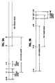
- the ERL difference values vary in the range between +3 dB and -3 dB during the first talking mode, between 6 dB and 20 dB during the second talking mode, between -20 dB and -60 dB during the third talking mode, and between 10 dB and -30 dB during the fourth talking mode.
- the ERLE difference values vary in the range between 3 dB and -3 dB (Fig. 3B) during the first talking mode, between 6 dB and 35 dB during the second talking mode, between 3 dB and -3 dB during the third talking mode, and between 20 dB and 0 dB during the fourth talking mode.
- the ERL estimator 21 holds a maximum value of ERL estimate for a given input difference
- the ERLE estimator 25 holds a maximum ERLE estimate for a given input difference.
- each of the decision circuits 22 and 26 produces a logic-1 output as a likelihood indicator of the second talking mode and a logic-0 output as a likelihood indicator of the other talking modes.
- the outputs of the decision circuits 22 and 26 are applied to an estimation corrector 23 to change the direction of control on the ERL and ERLE estimation processes according to a combination of logic outputs of the decision circuits 22 and 26 .
- Estimation corrector 23 includes a decision logic 43 and a pair of up-down counters 44 , 45 .
- Decision logic 43 decodes the logic states of the decision circuits 22 , 26 to identify them as one of the first, second, third and fourth talking modes, and drives the up-down counters 44 and 45 in either direction of count.
- Each of counters 44 and 45 produces an output when a full count value is reached.
- the outputs of counters 44 and 45 are applied respectively to the ERLE and ERL estimators 21 and 25 to modify their estimation control processes.
- An AND gate 27 is connected to receive logic signals from the decision circuits 22 and 26 to produce a logic-1 output for enabling the echo estimator 7 during the second talking mode and a logic-0 for disabling it during the other talking modes.
- Difference detector 20 includes a pair of average circuits 30 and 31 respectively connected to leads 4 and 9 to produce a pair of output signals respectively representing the average level of voltages.
- the difference between the average levels of the signals is detected by a subtractor 32 and applied to a comparator 33 where it is compared with the output of a memory 34 in which the most recent difference value is stored.
- the memory 34 is constantly updated by an update circuit 35 in response to the logic levels of the output of comparator 33 and the stored value of memory 34 .
- the update circuit 35 comprises switches 70 and 71 whose positions depend on first and second outputs of comparator 33 , respectively.
- a pair of read-only memories 72 and 73 is connected to the output of memory 34 .
- Each of these ROMs is of contents addressable type.
- In the ROM 72 are stored difference signals whose decibel values are greater than corresponding signals stored in memory 34 by 1 dB and a corresponding signal is read out of ROM 72 in response to the output of memory 34
- the ROM 73 are stored difference signals whose decibel values are smaller than the output of memory 34 by 1 dB and a corresponding signal is read out of ROM 73 in response to the output of memory 34 .
- the outputs of ROMs 72 and 73 are connected to the first and second terminals of the switch 71 , respectively.
- the first output of comparator 33 is a 0 when the value stored in memory 34 equals the difference detected by subtractor 32 and, in response, switch 70 is changed to the first terminal for coupling the output of memory 34 to the first terminal of switch 71 .
- the first output of comparator 33 changes to a 1 when the stored value of memory 34 is either lower or greater than the subtractor 32 output and, in response, the switch 70 is changed to the second terminal for coupling the output of ROM 72 to the first terminal of switch 71 .
- the second output of comparator 33 is a 0 when the stored value of memory 34 is equal to or higher than the subtractor 32 output and, in response, switch 71 is changed to the first terminal for coupling the output of switch 70 to the memory 34 .
- the second output of comparator 33 changes to a 1 when the stored value of memory 34 is lower than the subtractor 32 output and, in response, switch 71 is changed to the second terminal for coupling the output of ROM 73 to the memory 34 .
- the difference output of subtractor 32 is greater than the most recent value of memory 34 , the latter is incremented by 1 dB and if it is smaller than the most recent value, the latter is decremented by 1 dB.
- the output of update circuit 35 thus assumes the same value as the content of memory 34 as long as the output of subtractor 32 equals the most recent value of memory 34 .
- the output of update circuit 35 is supplied as an output of difference detector 20 to the ERL estimator 21 and decision circuit 22 .
- the ERL estimator 21 includes a subtractor 36 having a positive input connected to the output of difference detector 20 and a negative input connected to the output of a memory 37 in which an estimated ERL value is stored, so that the output of subtractor 36 represents the difference between an ERL estimate and the output of difference detector 20 .
- the output of subtractor 36 is connected to a comparator 38 where it is compared with a threshold value "- ⁇ 1 " which is determined from the range of the second talking mode shown in Fig. 3A.
- a threshold value "- ⁇ 1 " which is determined from the range of the second talking mode shown in Fig. 3A.
- the update circuit 40 includes contents-addressable read-only memories 80 and 81 .
- the ROM 80 are stored ERL estimates whose decibel values are greater than most recent ERL values by 1 dB and in the ROM 81 are stored ERL estimates whose values are smaller than the current values by 1 dB.
- the output of memory 37 is connected to the inputs of these ROMs as an address signal to read out corresponding ERL estimates.
- An incremented ERL estimate is read out of ROM 80 in response to a corresponding current estimate and supplied to the second terminal of a switch 82 and a decremented estimate is likewise read out of ROM 81 corresponding to the current estimate and supplied to the second terminal of a switch 83 whose first terminal is connected to the output of switch 82 .
- the first terminal of switch 82 is connected direct to the output of memory 37 to select it as a current value.
- the output of updown counter 39 of ERL estimator 21 is applied to switch 82 when a full count is reached in counter 39 for coupling an incremented ERL estimate from ROM 80 through the first terminal of switch 83 to the current memory 37 .
- the output of up-down counter 44 of estimation corrector 23 is connected to switch 83 .
- switch 83 is changed in position to the second terminal for coupling a decremented ERL estimate from ROM 81 to memory 37 .
- the memory 37 is incremented by 1 dB when switch 82 is changed to the second terminal when a full count is reached in counter 39 or decremented by 1 dB when switch 83 is changed to the second terminal when a full count is reached in counter 44 , whose operation will be described later.
- the threshold value ⁇ 1 the ERL estimation loop will hunt for a maximum ERL value which is eventually stored in memory 37 .
- the decision circuit 22 includes a comparator 41 and a threshold setting circuit implemented with a subtractor 42 .
- the output of the ERL estimator 21 is coupled to the subtractor 42 .
- a bias value of ⁇ 1 (typically 6 dB) is applied to subtractor 42 to be subtracted from the ERL estimate to supply a corrected ERL estimate to the comparator 41 as a threshold value.
- the output of difference detector 20 is compared against the threshold by comparator 41 .
- a logic-1 output is produced by comparator 41 when the output of difference detector 20 is higher than the threshold, or a logic-0 output is produced when it is lower than the threshold.
- the ERLE estimation circuit 101 is similarly constructed to the ERL estimation circuit 100 .
- Difference detector 24 includes a pair of average circuits 50 and 51 respectively connected to leads 4 and 10 to produce a pair of output signals respectively representing the average level of voltages.
- the difference between the average levels of the signals is detected by a subtractor 52 and applied to a comparator 53 where it is compared with the output of a memory 54 in which the most recent difference value is stored.
- the memory 54 is constantly updated by an update circuit 55 in response to the logic levels of the output of comparator 53 and the stored value of memory 54 .
- the update circuit 55 comprises switches 70 and 71 whose positions depend on first and second outputs of comparator 53 , respectively.
- a pair of read-only memories 72 and 73 is connected to the output of memory 54 .
- Each of these ROMs is of contents addressable type.
- In the ROM 72 are stored difference signals whose decibel values are greater than corresponding signals stored in memory 54 by 1 dB and a corresponding signal is read out of ROM 72 in response to the output of memory 54
- the ROM 73 are stored difference signals whose decibel values are smaller than the output of memory 54 by 1 dB and a corresponding signal is read out of ROM 73 in response to the output of memory 54 .
- the outputs of ROMs 72 and 73 are connected to the first and second terminals of the switch 71 , respectively.
- the first output of comparator 53 is a 0 when the value stored in memory 54 equals the difference detected by subtractor 52 and, in response, switch 70 is changed to the first terminal for coupling the output of memory 54 to the first terminal of switch 71 .
- the first output of comparator 53 changes to a 1 when the stored value of memory 54 is either lower or greater than the subtractor 52 output and, in response, the switch 70 is changed to the second terminal for coupling the output of ROM 72 to the first terminal of switch 71 .
- the second output of comparator 53 is a 0 when the stored value of memory 54 is equal to or higher than the subtractor 52 output and, in response, switch 71 is changed to the first terminal for coupling the output of switch 70 to the memory 54 .
- the second output of comparator 53 changes to a 1 when the stored value of memory 54 is lower than the subtractor 52 output and, in response, switch 71 is changed to the second terminal for coupling the output of ROM 73 to the memory 54 .
- the output of subtractor 52 is greater than the most recent value of memory 54 , the latter is incremented by 1 dB and if it is smaller than the most recent value, the latter is decremented by 1 dB.
- the output of update circuit 55 thus assumes the same value as the content of memory 54 as long as the output of subtractor 52 equals the most recent value of memory 54 .
- the output of update circuit 55 is supplied as an output of difference detector 24 to the ERLE estimator 25 and decision circuit 26 .
- the ERLE estimator 25 includes a subtractor 56 having a positive input connected to the output of difference detector 24 and a negative input connected to the output of a memory 57 in which an estimated ERLE value is stored, so that the output of subtractor 56 represents the difference between an ERLE estimate and the output of difference detector 24 .
- the output of subtractor 56 is connected to a comparator 58 where it is compared with a threshold value "- ⁇ 2 " which is determined from the range of the second talking mode shown in Fig. 3B.
- comparator 58 decrements counter 59 by the predetermined trimming value.
- comparator 58 recognizes that the ERL estimate has attained a steady state value indicative of the second talking mode and the contents of counter 59 are unaltered.
- counter 59 reaches a predetermined full count value, it changes the logical state of its output, which is supplied to an update circuit 60 to increment the ERLE estimate of memory 57 .
- the update circuit 60 has the same configuration as update circuit 40 (Fig. 5). ERLE estimates, whose decibel values are greater than most recent ERLE values by 1 dB, are stored in ROM 80 and EPLE estimates, whose values are smaller than the current values by 1 dB, are stored in ROM 81 .
- the output of memory 57 is used an address input for reading corresponding ERLE estimates.
- An incremented ERLE estimate is read out of ROM 80 in response to a corresponding current estimate value and supplied to the second terminal of switch 82 and a decremented estimate value is likewise read out of ROM 81 corresponding to the current estimate and supplied to the second terminal of switch 83 .
- the first terminal of switch 82 is connected direct to the output of memory 57 to select it as a current value.
- the output of updown counter 59 of ERLE estimator 25 is applied to switch 82 when a full count is reached in counter 59 for coupling an incremented ERLE estimate from ROM 80 through the first terminal of switch 83 to the current memory 57 .
- the output of up-down counter 45 of estimation corrector 23 is connected to switch 83 .
- switch 83 is changed to the second terminal for coupling a decremented ERLE estimate from ROM 81 to memory 57 . In this way, memory 57 holds its value as long as switches 82 and 83 remain connected to their first terminal.
- the memory 57 is incremented by 1 dB when switch 82 is changed to the second terminal when a full count is reached in counter 59 or decremented by 1 dB when switch 83 is changed to the second terminal when a full count is reached in counter 45 , whose operation will be described later.
- the ERLE estimation loop will hunt for a maximum ERLE value which is eventually stored in memory 57 .
- the decision circuit 26 is similar to decision circuit 22 .
- the output of the ERLE estimator 25 is coupled to the subtractor 62 and a bias value of ⁇ 2 (typically 12 dB) is subtracted from the ERLE estimate to supply a corrected ERLE estimate to comparator 61 as a threshold value.
- the output of difference detector 24 is compared against the threshold by comparator 61 , which produces a logic-1 output when the output of difference detector 24 is higher than the threshold, or a logic-0 output when it is lower than the threshold.
- the logic-1 output of the decision circuit 22 indicates that it is likely that the ERL estimate represents the second talking mode, and likewise the logic-1 output of the decision circuit 26 indicates that it is likely that the ERLE estimate represents the second talking mode. Therefore, the simultaneous occurrence of 1's at the outputs of decision circuits 22 and 26 provides a clear indication of the second talking mode.
- the decision logic 43 of estimation corrector 23 includes a pair of NOR gates 90 and 93 and a pair of NOT circuits 91 and 92 .
- the output of decision circuit 22 is applied to NOR gates 90 and 93 , one being direct to NOR gate 90 and the other through NOT gate 91 to NOR gate 93 .
- the output of decision circuit 26 is likewise applied to NOR gates 90 and 93 , one being direct to NOR gate 93 , the other being through NOT gate 92 to NOR gate 90 .
- the outputs of NOR gates 90 and 93 are connected to the up-count input of counters 44 and 45 , respectively and the outputs of NOT circuits 91 and 92 are connected to the down-count input of counters 44 and 45 , respectively.
- the up-down counters 44 , 45 increment their count value by a predetermined amount only when a 1 is applied to their up-count input and decrement it by the predetermined amount only when a 0 is applied to their down-count input.
- the up-down counters 44 and 45 reach their full count value they supply an output signal to the switch 83 of update circuits 40 and 60 , respectively, to cause the ERL and ERLE estimates to decrement by 1 dB.
Landscapes
- Engineering & Computer Science (AREA)
- Computer Networks & Wireless Communication (AREA)
- Signal Processing (AREA)
- Cable Transmission Systems, Equalization Of Radio And Reduction Of Echo (AREA)
Claims (6)
- Sprachaktivitätsdetektor zum Steuern einer in einem Echokompensator angeordneten Einrichtung zum Bestimmen von Schätzwerten, wobei der Echokompensator ein Echosignal kompensiert, das von einem Empfangsweg der Vierdrahtschaltung einer Übertragungsgabelschaltung in einen Sendeweg der Vierdrahtschaltung eingekoppelt wird, wobei der Sprachaktivitätsdetektor aufweist:eine erste Differenzdetektoreinrichtung (20) zum Erfassen einer Differenz zwischen einer mittleren Spannung am Empfangsweg und einer Spannung am Sendeweg und zum Erzeugen eines ersten Differenzsignals aus der Differenz;eine erste Einrichtung (21) zum Bestimmen von Schätzwerten zum Erzeugen eines Echorückflußdämpfungs- (ERL) Schätzwertes aus dem ersten Differenzsignal;eine erste Entscheidungseinrichtung (22) zum Vergleichen des ersten Differenzsignals mit dem ERL-Schätzwert, um daraus ein erstes Binärsignal zu erzeugen;eine zweite Differenzdetektoreinrichtung (24) zum Erfassen einer Differenz zwischen der mittleren Spannung am Sendeweg und einer Ausgangsspannung des Echokompensators und zum Erzeugen eines zweiten Differenzsignals aus der Differenz;eine zweite Einrichtung (25) zum Bestimmen von Schätzwerten zum Erzeugen eines Echorückflußdämpfungszunahme- (ERLE) Schätzwertes aus dem zweiten Differenzsignal;eine zweite Entscheidungseinrichtung (26) zum Vergleichen des zweiten Differenzsignals mit dem ERLE-Schätzwert, um ein zweites Binärsignal zu erzeugen, das zusammen mit dem ersten Binärsignal mehrere Kombinationen von Binärpegeln bildet; undeine Einrichtung (27) zum Aktivieren der im Echokompensator angeordneten Einrichtung zum Bestimmen von Schätzwerten in Antwort auf eine vorgegebene der Kombinationen von Binärpegeln und zum reaktivieren der im Echokompensator angeordneten Einrichtung zum Bestimmen von Schätzwerten in Antwort auf von der vorgegebenen Kombination verschiedene Kombinationen.
- Sprachaktivitätsdetektor nach Anspruch 1, ferner mit einer Schätzwertkorrektureinrichtung (23) zum Analysieren der Kombinationen des ersten und des zweiten Binärsignals, um ein erstes und ein zweites Korrektursignal zu erzeugen, und zum Zuführen des ersten und des zweiten Korrektursignals zur ersten bzw. zur zweiten Einrichtung zum Bestimmen von Schätzwerten, um die ERL-und ERLE-Schätzwerte zu korrigieren.
- Sprachaktivitätsdetektor nach Anspruch 1 oder 2, ferner mit:einer Entscheidungslogikeinrichtung (43) zum Analysieren der Kombinationen der ersten und der zweiten Binärsignale und zum Erzeugen eines ersten und eines zweiten Steuersignals;einem ersten Vorwärts/Rückwärtszähler (44) zum Ändern eines Zählwertes gemäß der ersten Steuersignal und zum Erzeugen eines Ausgangssignals, wenn ein Endzählwert erreicht ist; undeinem zweiten Vorwärts/Rückwärtszähler (45) zum Ändern eines Zählwertes gemäß dem zweiten Steuersignal und zum Erzeugen eines Ausgangssignals, wenn ein Endzählwert erreicht ist;wobei die erste Einrichtung (21) zum Bestimmen von Schätzwerten aufweist:einen ersten Speicher (37) zum Speichern eines Schätzwertes;ein erstes Subtrahierglied (36) zum Erfassen einer Differenz zwischen dem ersten Differenzsignal und dem im ersten Speicher (37) gespeicherten Schätzwert;einen ersten Vergleicher (38) zum Vergleichen der durch das erste Subtrahierglied erfaßten Differenz mit einem ersten Referenzwert;einem dritten Vorwärts/Rückwärtszähler (39) zum Ändern eines Zählwertes gemäß einem Ausgangssignal des ersten Vergleichers und zum Erzeugen eines Ausgangssignals, wenn ein Endzählwert erreicht ist; undeine erste Aktualisierungseinrichtung (40) zum Erzeugen des ERL-Schätzwertes durch Erhöhen des im ersten Speicher gespeicherten Schätzwertes um einen Einheitswert in Antwort auf das Ausgangssignal des dritten Vorwärts/Rückwärtszähles und zum Vermindern des gespeicherten Schätzwertes um einen Einheitswert in Antwort auf das Ausgangssignal des ersten Vorwärts/Rückwärtszählers (44);wobei die zweite Einrichtung (25) zum Bestimmen von Schätzwerten aufweist:einer zweiten Speicher (57) zum Speichern eines Schätzwertes;ein zweites Subtrahierglied (56) zum Erfassen einer Differenz zwischen dem zweiten Differenzsignal und dem im zweiten Speicher (57) gespeicherten Schätzwert;einen zweiten Vergleicher (58) zum Vergleichen der durch das zweite Subtrahierglied erfaßten Differenz mit einem zweiten Referenzwert;einen vierten Vorwärts/Rückwärtszähler (59) zum Ändern eines Zählwertes gemäß einem Ausgangssignal des zweiten Vergleichers und zum Erzeugen eines Ausgangssignals, wenn ein Endzählwert erreicht wird; undeine zweite Aktualisierungseinrichtung (60) zum Erzeugen des ERLE-Schätzwertes durch Erhöhen des im zweien Speicher gespeicherten Schätzwertes in Antwort auf das Ausgangssignal des vierten Vorwärts/Rückwärtszählers (59) um einen Einheitswert und zum Vermindern des gespeicherten Schätzwertes in Antwort auf das Ausgangssignal des zweiten Vorwärts/Rückwärtszählers (45) um einen Einheitswert.
- Sprachaktivitätsdetektor nach Anspruch 1, 2 oder 3, wobei die erste Differenzdetektoreinrichtung (20) aufweist:ein erstes Paar Mittelwertbildungsschaltungen (30, 31) zum Erfassen eines Mittelwertes der Spannung am Empfangsweg und eines Mittelwertes der Spannung am Sendeweg;ein drittes Subtrahierglied (32) zum Erfassen eines Differenzwertes zwischen den durch das erste Paar Mittelwertbildungsschaltungen erfaßten Mittelwerten;einen dritten Speicher (34) zum Speichern eines Differenzwertes;einen dritten Vergleicher (33) zum Erfassen einer Differenz zwischen dem im dritten Speicher (34) gespeicherten Differenzwert und dem durch das dritte Subtrahierglied (32) erfaßten Differenzwert; undeine dritte Aktualisierungseinrichtung (35) zum Erzeugen des ersten Differenzsignals durch Ändern des im dritter Speicher (34) gespeicherten Differenzwertes gemäß einem Ausgangssignal des Vergleichers (33);wobei die zweite Differenzdetektoreinrichtung (24) aufweist:ein zweites Paar Mittelwertbildungsschaltungen (50, 51) zum Erfassen eines Mittelwertes der Spannung am Sendeweg und eines Mittelwertes der Ausgangsspannung des Echokompensators;ein viertes Subtrahierglied (52) zum Erfassen eines Differenzwertes zwischen den durch das zweite Paar Mittelwertbildungsschaltungen erfaßten Mittelwerten;einen vierten Speicher (54) zum Speichern eines Differenzwertes;einen vierten Vergleicher (53) zum Erfassen einer Differenz zwischen dem im vierten Speicher (54) gespeicherten Differenzwert und dem durch das vierte Subtrahierglied (52) erfaßten Differenzwert; undeine vierte Aktualisierungseinrichtung (55) zum Erzeugen des zweiten Differenzsignals durch Ändern des im vierten Speicher (54) gespeicherten Differenzwertes gemäß einem Ausgangssignal des vierten Vergleichers (53).
- Sprachaktivitätsdetektor nach einem der Ansprüche 1 bis 4, wobei die erste Entscheidungseinrichtung (22) eine Einrichtung (42) zum Subtrahieren eines ersten vorgegebenen Wertes vom ERL-Schätzwert aufweist, um einen ersten Schwellenwert zu erzeugen, und einen Vergleicher (41) zum Vergleichen des ersten Differenzsignals mit dem ersten Schwellenwert und zum Erzeugen einer Binärziffer durch einen von zwei diskreten Pegeln als erstes Binärsignal in Abhängigkeit davon, ob das erste Differenzsignal größer oder kleiner ist als der erste Schwellenwert;
wobei die zweite Entscheidungseinrichtung (26) eine Einrichtung zum Subtrahieren eines zweiten vorgegebenen Wertes vom ERLE-Schätzwert aufweist, um einen zweiten Schwellenwert zu erzeugen, und einen Vergleicher zum Vergleichen des zweiten Differenzsignals mit dem zweiten Schwellenwert und zum Erzeugen einer Binärziffer durch einen von zwei diskreten Pegeln als zweites Binärsignal in Abhängigkeit davon, ob das zweite Differenzsignal größer oder kleiner ist als der zweite Schwellenwert. - Verfahren zum Steuern eines Echokompensators für einen Sprachaktivitätsdetektor zum Steuern einer im Echokompensator angeordneten Einrichtung zum Bestimmen von Schätzwerten, wobei der Echokompensator ein Echosignal kompensiert, das von einem Empfangsweg der Vierdrahtschaltung einer Übertragungsgabelschaltung in einen Sendeweg der Vierdrahtschaltung eingekoppelt wird, mit den Schritten:a) Erfassen einer Differenz zwischen einer Spannung am Empfangsweg und einer Spannung am Sendeweg, um daraus ein erstes Differenzsignal zu erzeugen, und Erfassen einer Differenz zwischen der Spannung am Sendeweg und einer Ausgangsspannung des Echokompensators, um daraus ein zweites Differenzsignal zu erzeugen;b) Erzeugen eines Echorückflußdämpfungs- (ERL) Schätzwertes aus dem ersten Differenzsignal und Erzeugen eines Echorückflußdämpfungszunahme- (ERLE) Schätzwertes aus dem zweiten Differenzsignal;c) Vergleichen des ersten Differenzsignals mit dem ERL-Schätzwert, um ein erstes Binärsignal zu erzeugen, und Vergleichen des zweiten Differenzsignals mit dem ERLE-Schätzwert, um ein zweites Binärsignal zu erzeugen, das zusammen mit dem ersten binärsignal eine von mehreren Kombinationen von Binärpegeln bildet; undc) Aktivieren der im Echokompensator angeordneten Einrichtung zum Bestimmen von Schätzwerten in Antwort auf eine vorgegebene der Kombinationen von binärpegeln und Deaktivieren der im Echokompensator angeordneten Einrichtung zum Bestimmen von Schätzwerten in Antwort auf von der vorgegebenen Kombination verschiedene Kombinationen.
Applications Claiming Priority (3)
| Application Number | Priority Date | Filing Date | Title |
|---|---|---|---|
| JP339056/92 | 1992-12-18 | ||
| JP4339056A JPH07123236B2 (ja) | 1992-12-18 | 1992-12-18 | 双方向通話状態検出回路 |
| JP33905692 | 1992-12-18 |
Publications (3)
| Publication Number | Publication Date |
|---|---|
| EP0604870A2 EP0604870A2 (de) | 1994-07-06 |
| EP0604870A3 EP0604870A3 (de) | 1994-11-17 |
| EP0604870B1 true EP0604870B1 (de) | 1999-08-11 |
Family
ID=18323843
Family Applications (1)
| Application Number | Title | Priority Date | Filing Date |
|---|---|---|---|
| EP93120547A Expired - Lifetime EP0604870B1 (de) | 1992-12-18 | 1993-12-20 | Anordnung zur Feststellung der Anwesenheit von Sprachsignalen zur Regelung eines Echokompensators |
Country Status (5)
| Country | Link |
|---|---|
| US (1) | US5434916A (de) |
| EP (1) | EP0604870B1 (de) |
| JP (1) | JPH07123236B2 (de) |
| CA (1) | CA2111939C (de) |
| DE (1) | DE69325979T2 (de) |
Families Citing this family (28)
| Publication number | Priority date | Publication date | Assignee | Title |
|---|---|---|---|---|
| WO1996025733A1 (en) * | 1995-02-15 | 1996-08-22 | British Telecommunications Public Limited Company | Voice activity detection |
| US5606550A (en) * | 1995-05-22 | 1997-02-25 | Hughes Electronics | Echo canceller and method for a voice network using low rate coding and digital speech interpolation transmission |
| US5764753A (en) * | 1995-09-29 | 1998-06-09 | Crystal Semiconductor Corp. | Half-duplex controller |
| TW432855B (en) | 1996-04-25 | 2001-05-01 | Mitsubishi Electric Corp | Echo eliminator |
| US5765130A (en) * | 1996-05-21 | 1998-06-09 | Applied Language Technologies, Inc. | Method and apparatus for facilitating speech barge-in in connection with voice recognition systems |
| US5771440A (en) * | 1996-05-31 | 1998-06-23 | Motorola, Inc. | Communication device with dynamic echo suppression and background noise estimation |
| US6111949A (en) * | 1996-09-04 | 2000-08-29 | Teltrend, Inc. | Method of rapid automatic hybrid balancing |
| US5953412A (en) * | 1996-09-04 | 1999-09-14 | Teltrend, Inc. | Method and apparatus for controlling line conditioner equalizer |
| US5974137A (en) * | 1996-09-04 | 1999-10-26 | Teltrend, Inc. | AGC amplifier for two-wire line conditioner |
| US5963638A (en) * | 1996-09-04 | 1999-10-05 | Teltrend, Inc. | Adjustable hybrid having improved biasing configuration |
| US6198819B1 (en) * | 1997-11-14 | 2001-03-06 | Tellabs Operations, Inc. | Echo canceller having improved non-linear processor |
| US6031908A (en) * | 1997-11-14 | 2000-02-29 | Tellabs Operations, Inc. | Echo canceller employing dual-H architecture having variable adaptive gain settings |
| US6148078A (en) * | 1998-01-09 | 2000-11-14 | Ericsson Inc. | Methods and apparatus for controlling echo suppression in communications systems |
| DE19850271A1 (de) * | 1998-10-31 | 2000-05-04 | Alcatel Sa | Verfahren zur Bestimmung eines Echokopplungsfaktors und der Echolaufzeit in einem bidirektionalen Telekommunikationssystem |
| US6694019B1 (en) * | 1999-08-26 | 2004-02-17 | Nortel Networks Limited | Method and apparatus for infinite return loss handler for network echo canceller |
| US6754337B2 (en) * | 2002-01-25 | 2004-06-22 | Acoustic Technologies, Inc. | Telephone having four VAD circuits |
| US6961421B2 (en) * | 2002-06-17 | 2005-11-01 | Texas Instruments Incorporated | Echo analysis for identification of hybrid induced echo in a communication link |
| US7856097B2 (en) | 2004-06-17 | 2010-12-21 | Panasonic Corporation | Echo canceling apparatus, telephone set using the same, and echo canceling method |
| GB2416971A (en) * | 2004-08-04 | 2006-02-08 | Mitel Networks Corp | Calculating an expected echo return loss enhancement (erle) in an echo canceller |
| US7724693B2 (en) * | 2005-07-28 | 2010-05-25 | Qnx Software Systems (Wavemakers), Inc. | Network dependent signal processing |
| US8326614B2 (en) | 2005-09-02 | 2012-12-04 | Qnx Software Systems Limited | Speech enhancement system |
| EP2107553B1 (de) * | 2008-03-31 | 2011-05-18 | Harman Becker Automotive Systems GmbH | Verfahren zur Erkennung einer Unterbrechung einer Sprachausgabe |
| EP2148325B1 (de) * | 2008-07-22 | 2014-10-01 | Nuance Communications, Inc. | Verfahren zur Bestimmung der Anwesenheit einer gewollten Signalkomponente |
| US20100304679A1 (en) * | 2009-05-28 | 2010-12-02 | Hanks Zeng | Method and System For Echo Estimation and Cancellation |
| KR20120091068A (ko) * | 2009-10-19 | 2012-08-17 | 텔레폰악티에볼라겟엘엠에릭슨(펍) | 음성 활성 검출을 위한 검출기 및 방법 |
| EP2850611B1 (de) | 2012-06-10 | 2019-08-21 | Nuance Communications, Inc. | Rauschabhängige signalverarbeitung für fahrzeugkommunikationssystem mit mehreren akustischen zonen |
| US9805738B2 (en) | 2012-09-04 | 2017-10-31 | Nuance Communications, Inc. | Formant dependent speech signal enhancement |
| US9613633B2 (en) | 2012-10-30 | 2017-04-04 | Nuance Communications, Inc. | Speech enhancement |
Family Cites Families (7)
| Publication number | Priority date | Publication date | Assignee | Title |
|---|---|---|---|---|
| US3497641A (en) * | 1967-08-02 | 1970-02-24 | Bell Telephone Labor Inc | Test set for evaluation of echo suppressors |
| DE3070399D1 (en) * | 1980-12-06 | 1985-05-02 | Communications Satellite Corp | Improved double talk detector for echo cancellers |
| FR2517499A1 (fr) * | 1981-11-27 | 1983-06-03 | Cit Alcatel | Procede et dispositif de detection de signaux de donnees et de signalisation sur une voie telephonique |
| US4918727A (en) * | 1988-06-09 | 1990-04-17 | Tellabs Incorporated | Double talk detector for echo canceller and method |
| DE3840433A1 (de) * | 1988-12-01 | 1990-06-07 | Philips Patentverwaltung | Echokompensator |
| FR2651077B1 (fr) * | 1989-08-18 | 1994-06-10 | Letourneur Gregoire | Dispositif de traitement d'echo notamment acoustique dans une ligne telephonique |
| JP3200932B2 (ja) * | 1992-03-24 | 2001-08-20 | 株式会社日立製作所 | 電子対話システム |
-
1992
- 1992-12-18 JP JP4339056A patent/JPH07123236B2/ja not_active Expired - Fee Related
-
1993
- 1993-12-20 EP EP93120547A patent/EP0604870B1/de not_active Expired - Lifetime
- 1993-12-20 CA CA002111939A patent/CA2111939C/en not_active Expired - Fee Related
- 1993-12-20 DE DE69325979T patent/DE69325979T2/de not_active Expired - Fee Related
- 1993-12-20 US US08/169,634 patent/US5434916A/en not_active Expired - Fee Related
Also Published As
| Publication number | Publication date |
|---|---|
| CA2111939A1 (en) | 1994-06-19 |
| US5434916A (en) | 1995-07-18 |
| DE69325979D1 (de) | 1999-09-16 |
| EP0604870A3 (de) | 1994-11-17 |
| JPH07123236B2 (ja) | 1995-12-25 |
| DE69325979T2 (de) | 1999-12-23 |
| EP0604870A2 (de) | 1994-07-06 |
| CA2111939C (en) | 1998-10-27 |
| JPH06188789A (ja) | 1994-07-08 |
Similar Documents
| Publication | Publication Date | Title |
|---|---|---|
| US5434916A (en) | Voice activity detector for controlling echo canceller | |
| US5563944A (en) | Echo canceller with adaptive suppression of residual echo level | |
| US7031459B2 (en) | Echo canceller employing dual-H architecture having improved non-linear echo path detection | |
| US4360712A (en) | Double talk detector for echo cancellers | |
| US7020278B2 (en) | Echo canceller having improved non-linear processor | |
| CA2004005C (en) | Echo canceller | |
| US4894820A (en) | Double-talk detection in an echo canceller | |
| US5745564A (en) | Echo cancelling arrangement | |
| US4852161A (en) | Echo canceller using an echo path status detection | |
| US6947552B2 (en) | Echo canceler with echo path change detector | |
| US4554417A (en) | Tandem adaptive echo canceler arrangement | |
| US4064378A (en) | Echo cancelling system for multiplex telephone circuits | |
| US5327495A (en) | Apparatus and method for controlling an echo canceler | |
| EP0053202A1 (de) | Detektor für gleichzeitiges Sprechen bei Echounterdrückern | |
| US4368360A (en) | Adaptive control type echo suppressor | |
| EP0803990A2 (de) | Echounterdrücker mit Gegensprechdetektor | |
| CA1146289A (en) | Double talk detector for echo cancellers | |
| CA2580432A1 (en) | Echo canceller employing dual-h architecture having improved non-linear echo path detection | |
| JPH0472924A (ja) | エコーキヤンセラの双方向通話検出回路 |
Legal Events
| Date | Code | Title | Description |
|---|---|---|---|
| PUAI | Public reference made under article 153(3) epc to a published international application that has entered the european phase |
Free format text: ORIGINAL CODE: 0009012 |
|
| AK | Designated contracting states |
Kind code of ref document: A2 Designated state(s): DE FR GB |
|
| PUAL | Search report despatched |
Free format text: ORIGINAL CODE: 0009013 |
|
| AK | Designated contracting states |
Kind code of ref document: A3 Designated state(s): DE FR GB |
|
| 17P | Request for examination filed |
Effective date: 19941006 |
|
| 17Q | First examination report despatched |
Effective date: 19971203 |
|
| GRAG | Despatch of communication of intention to grant |
Free format text: ORIGINAL CODE: EPIDOS AGRA |
|
| GRAG | Despatch of communication of intention to grant |
Free format text: ORIGINAL CODE: EPIDOS AGRA |
|
| GRAG | Despatch of communication of intention to grant |
Free format text: ORIGINAL CODE: EPIDOS AGRA |
|
| GRAH | Despatch of communication of intention to grant a patent |
Free format text: ORIGINAL CODE: EPIDOS IGRA |
|
| GRAH | Despatch of communication of intention to grant a patent |
Free format text: ORIGINAL CODE: EPIDOS IGRA |
|
| GRAA | (expected) grant |
Free format text: ORIGINAL CODE: 0009210 |
|
| AK | Designated contracting states |
Kind code of ref document: B1 Designated state(s): DE FR GB |
|
| REF | Corresponds to: |
Ref document number: 69325979 Country of ref document: DE Date of ref document: 19990916 |
|
| ET | Fr: translation filed | ||
| PLBE | No opposition filed within time limit |
Free format text: ORIGINAL CODE: 0009261 |
|
| STAA | Information on the status of an ep patent application or granted ep patent |
Free format text: STATUS: NO OPPOSITION FILED WITHIN TIME LIMIT |
|
| 26N | No opposition filed | ||
| REG | Reference to a national code |
Ref country code: GB Ref legal event code: IF02 |
|
| PGFP | Annual fee paid to national office [announced via postgrant information from national office to epo] |
Ref country code: FR Payment date: 20041208 Year of fee payment: 12 |
|
| PGFP | Annual fee paid to national office [announced via postgrant information from national office to epo] |
Ref country code: GB Payment date: 20041215 Year of fee payment: 12 |
|
| PGFP | Annual fee paid to national office [announced via postgrant information from national office to epo] |
Ref country code: DE Payment date: 20041216 Year of fee payment: 12 |
|
| PG25 | Lapsed in a contracting state [announced via postgrant information from national office to epo] |
Ref country code: GB Free format text: LAPSE BECAUSE OF NON-PAYMENT OF DUE FEES Effective date: 20051220 |
|
| PG25 | Lapsed in a contracting state [announced via postgrant information from national office to epo] |
Ref country code: DE Free format text: LAPSE BECAUSE OF NON-PAYMENT OF DUE FEES Effective date: 20060701 |
|
| GBPC | Gb: european patent ceased through non-payment of renewal fee |
Effective date: 20051220 |
|
| PG25 | Lapsed in a contracting state [announced via postgrant information from national office to epo] |
Ref country code: FR Free format text: LAPSE BECAUSE OF NON-PAYMENT OF DUE FEES Effective date: 20060831 |
|
| REG | Reference to a national code |
Ref country code: FR Ref legal event code: ST Effective date: 20060831 |