EP0604886A2 - Récipient à mode de chauffage électrique - Google Patents
Récipient à mode de chauffage électrique Download PDFInfo
- Publication number
- EP0604886A2 EP0604886A2 EP93120605A EP93120605A EP0604886A2 EP 0604886 A2 EP0604886 A2 EP 0604886A2 EP 93120605 A EP93120605 A EP 93120605A EP 93120605 A EP93120605 A EP 93120605A EP 0604886 A2 EP0604886 A2 EP 0604886A2
- Authority
- EP
- European Patent Office
- Prior art keywords
- cooking vessel
- vessel according
- passage
- thermostat
- steam
- Prior art date
- Legal status (The legal status is an assumption and is not a legal conclusion. Google has not performed a legal analysis and makes no representation as to the accuracy of the status listed.)
- Granted
Links
Images


Classifications
-
- H—ELECTRICITY
- H05—ELECTRIC TECHNIQUES NOT OTHERWISE PROVIDED FOR
- H05B—ELECTRIC HEATING; ELECTRIC LIGHT SOURCES NOT OTHERWISE PROVIDED FOR; CIRCUIT ARRANGEMENTS FOR ELECTRIC LIGHT SOURCES, IN GENERAL
- H05B3/00—Ohmic-resistance heating
- H05B3/68—Heating arrangements specially adapted for cooking plates or analogous hot-plates
-
- A—HUMAN NECESSITIES
- A47—FURNITURE; DOMESTIC ARTICLES OR APPLIANCES; COFFEE MILLS; SPICE MILLS; SUCTION CLEANERS IN GENERAL
- A47J—KITCHEN EQUIPMENT; COFFEE MILLS; SPICE MILLS; APPARATUS FOR MAKING BEVERAGES
- A47J27/00—Cooking-vessels
- A47J27/002—Construction of cooking-vessels; Methods or processes of manufacturing specially adapted for cooking-vessels
-
- B—PERFORMING OPERATIONS; TRANSPORTING
- B23—MACHINE TOOLS; METAL-WORKING NOT OTHERWISE PROVIDED FOR
- B23K—SOLDERING OR UNSOLDERING; WELDING; CLADDING OR PLATING BY SOLDERING OR WELDING; CUTTING BY APPLYING HEAT LOCALLY, e.g. FLAME CUTTING; WORKING BY LASER BEAM
- B23K20/00—Non-electric welding by applying impact or other pressure, with or without the application of heat, e.g. cladding or plating
- B23K20/12—Non-electric welding by applying impact or other pressure, with or without the application of heat, e.g. cladding or plating the heat being generated by friction; Friction welding
- B23K20/129—Non-electric welding by applying impact or other pressure, with or without the application of heat, e.g. cladding or plating the heat being generated by friction; Friction welding specially adapted for particular articles or work
-
- H—ELECTRICITY
- H05—ELECTRIC TECHNIQUES NOT OTHERWISE PROVIDED FOR
- H05B—ELECTRIC HEATING; ELECTRIC LIGHT SOURCES NOT OTHERWISE PROVIDED FOR; CIRCUIT ARRANGEMENTS FOR ELECTRIC LIGHT SOURCES, IN GENERAL
- H05B2203/00—Aspects relating to Ohmic resistive heating covered by group H05B3/00
- H05B2203/017—Manufacturing methods or apparatus for heaters
-
- H—ELECTRICITY
- H05—ELECTRIC TECHNIQUES NOT OTHERWISE PROVIDED FOR
- H05B—ELECTRIC HEATING; ELECTRIC LIGHT SOURCES NOT OTHERWISE PROVIDED FOR; CIRCUIT ARRANGEMENTS FOR ELECTRIC LIGHT SOURCES, IN GENERAL
- H05B2203/00—Aspects relating to Ohmic resistive heating covered by group H05B3/00
- H05B2203/021—Heaters specially adapted for heating liquids
Definitions
- the invention relates to an electrically heated cooking vessel, the aluminum heating plate is connected by a friction welded connection to the bottom wall of the cooking vessel and has a tubular heater.
- the tubular heater can be pressed on or inserted into a groove.
- a cooking vessel is to be understood as meaning cooking pots, casseroles, frying pans, deep-frying devices, egg cooking dishes, kettles and the like.
- An aluminum heating plate is desirable for reasons of heat transfer.
- a cooking appliance of the type mentioned is known from EP 0 307 555 B1.
- the aluminum heating plate is connected to the steel floor by applying pressure and heat. Fastening a thermostat or other functional parts to the aluminum heating plate requires special operations to fasten the same.
- a thermostat In the case of a cooking vessel serving as a kettle, a thermostat is known as a dry-cooking fuse to protect against overheating and / or burning through the tubular heating element. To avoid excessive evaporation of the water, the use of a steam thermostat is also known. A thermally favorable fastening and protection of the thermostat cause additional problems.
- the object of the invention is to simplify the fastening of components such as thermostats, bimetallic elements and the like.
- the aluminum heating plate has bolts and / or rivets which are shaped during friction welding and are used to fasten functional parts.
- the invention differs from the prior art by the simultaneous formation of the bolts and / or rivets, possibly with the formation of the groove during the friction welding process. This means that no special operation is required to form or attach the bolts.
- the rivets allow simple rivet attachment of components and functional parts.
- the aluminum heating plate consists of elastic soft aluminum.
- the attachment is possible in a safe manner that a thermostat is placed on the bolt and held by rivet heads.
- a support bridge made of a material with a lower thermal conductivity than aluminum is placed on bolts and supports the thermostat.
- the function of the steam thermostat is promoted in that a steam pipe is inserted into a passage in the bottom wall, in that a steam thermostat is arranged in the outlet area of the steam pipe and in that a thermostat acting as a dry-cooking fuse acts on a switch-off control device.
- a simple implementation is achieved in that the steam pipe is inserted into the passage with a seal.
- a modified connection is designed such that the edge of the passage sits in a fold in the steam pipe.
- a premature effect of the dry-cooking fuse is brought about by the fact that the thermostat for the dry-cook fuse is arranged in an internal curvature of the bottom of the vessel directed into the interior of the vessel.
- An automatic electric water boiler prevents water from entering the steam pipe in that a cage is provided below a downwardly open passage of the steam pipe's inlet pipe to accommodate a float body that closes the passage.
- the float body is designed as a lightweight hollow ball.
- a reliable valve action is achieved in that the cage consists of two chambers which are separated by an intermediate wall with a passage serving as a valve seat on both sides.
- a further protection against water ingress into the steam pipe is achieved in that the bottom wall of the cage is designed as a deflector plate which projects beyond the cage on all sides.
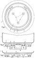
- a cooking vessel 1 is made of stainless steel and has an essentially flat bottom wall 2.
- An aluminum heating plate 3 made of elastic soft aluminum is integrally connected to the bottom wall 2 using pressure and heat.
- the aluminum heating plate 3 receives a tubular heater 5. The same can sit in a groove 4. This groove 4 is formed during the friction welding process. A different fastening of the radiator by pressing is also possible.
- bolts 6 and rivets 7 are formed by flow. This shaping is possible at any desired location on the aluminum heating plate.
- a thermostat 8 is placed on the bolts 6, the rivets 7 passing through passages.
- a rivet head 10 is formed over a washer 9. This sets the thermostat.
- the cooking vessel 1 shown in Fig. 4 as a kettle, saucepan, egg cooker or the like is made of stainless steel and also has a bottom wall 2 made of stainless steel.
- the cooking vessel is heated by an aluminum heating plate 3 connected to the bottom of the vessel, which receives a tubular heating element 5.
- the electrical connections of the tubular heater 5 are designed as lines 11 and connected to a connection line 17 or another connection device via a switch-off control device 12. In another way, the connections can also be designed as contact springs, as shown in FIG. 8.
- the cooking vessel can be locked by a lid 13.
- a steam pipe 14 reaching to the filling level is guided through a passage in the bottom wall 2.
- a steam thermostat 15 is arranged in the mouth region of the steam pipe 14.
- thermostat 8 is located on the heating plate 3 and serves as a dry-cooking fuse.
- thermostats 15 and 8 are connected to the switch-off control device 12.
- the steam and, on the other hand, overheating of the heating plate when the cooking vessel is empty can result in an automatic shutdown and thus protection of the tubular heater.
- the two thermostats 15 and 8 can be combined with one another. This depends on the thermostat elements available.
- a bottom shell 18 closes off the cooking vessel 1 and serves to protect the heating plate 3 and the switching elements.
- Fig. 5 shows an embodiment of the implementation of the steam pipe 14.
- a sealing collar 19 is inserted, which tightly surrounds the jacket of the steam pipe 14.
- Fig. 6 shows an implementation as a sheet metal connection.
- An outwardly directed flange 20 of the steam pipe 14 is crimped into a fold 21 of the bottom wall 2. This creates a tight connection.
- the edge of the passage can also be flanged into a fold 22 of the steam pipe 14. Modifications to these sheet metal connections are also possible.
- the thermostat 8 or the switch-off device 12 are attached to a support bridge 23.
- the support bridge 23 consists of a material with a lower thermal conductivity than aluminum.
- the thermostat 8 has a bimetallic switching element 24 which bears directly on the aluminum heating plate 3 or the bottom wall 2 and switches when heated accordingly. In this way you can achieve dry cook protection.
- the bottom wall 2 and the heating plate 3 have an internal curvature 35 directed into the interior of the vessel, into which the thermostat 8 is inserted with the aid of the support bridge 23.
- the inward inner curvature 35 becomes dry before the entire bottom wall 2 becomes dry. This enables the radiator to be switched off prematurely and thus improves dry cook protection.
- the electrical connections of the tubular heater 5 are designed as leaf springs 36.
- the leaf springs can have a suitable shape.
- the mouth of the steam pipe 14 is directed to a sensor 25 of the steam thermostat 15. An escape of excessive moisture or even water from the steam pipe 14 must be prevented so that the functional parts do not suffer from corrosion.
- the inlet pipe 26 of the steam pipe 14 is directed downward and is closed by a cage 27 with a deflector plate 28 on the bottom, which projects beyond the cage on all sides.
- the cage 27 comprises two chambers 31 and 32 separated by an intermediate wall 29 with a passage 30.
- the lower chamber 31 has lateral inlet openings and contains a float body 33 which is specifically lighter than water and therefore floats.
- the float body 33 can be a lightweight hollow ball.
- a heavy valve body 34 is located in the upper chamber 32 and abuts the edge of the passage 30.
- the passage 30 thus represents a two-sided valve seat.
- the valve body 32 enables the function of a flute of the kettle.
- valve body 34 delays the steam escape through the steam pipe by several s to more than 10 s. This is sufficient for a flute signal.
- the valve body 34 With increasing steam pressure, the valve body 34 is raised, so that steam influences the steam thermostat 15. The kettle is therefore switched off and the valve body 34 closes the steam pipe 14 again. This prevents a large amount of moist steam from reaching the thermostat and the electrical components through the steam pipe.
- the deflector plate 28 retains water splashes so that no water can enter the steam pipe. The passages are not affected by water either.
Landscapes
- Engineering & Computer Science (AREA)
- Manufacturing & Machinery (AREA)
- Food Science & Technology (AREA)
- Mechanical Engineering (AREA)
- Cookers (AREA)
- Baking, Grill, Roasting (AREA)
Applications Claiming Priority (12)
| Application Number | Priority Date | Filing Date | Title |
|---|---|---|---|
| DE9217353U DE9217353U1 (de) | 1992-12-21 | 1992-12-21 | Kochgefäß mit einer thermostatgesteuerten Heizplatte |
| DE9217353U | 1992-12-21 | ||
| DE9309335U DE9309335U1 (de) | 1993-06-23 | 1993-06-23 | Elektrisch beheiztes Kochgefäß |
| DE9309335U | 1993-06-23 | ||
| BE9300805A BE1007403A3 (nl) | 1993-08-02 | 1993-08-02 | Recipient uit roestvrijstaal met een aluminiumbodem, voorzien van stiften ter bevestiging van andere bouwcomponenten. |
| BE9300805 | 1993-08-02 | ||
| BE9301287 | 1993-11-22 | ||
| BE9301287A BE1007743A6 (nl) | 1993-11-22 | 1993-11-22 | Bevestigingsmethode van een thermostaat met kunststofbehuizing op een metalen verwarmingsbodem van een kookrecipient. |
| BE9301286A BE1007742A6 (nl) | 1993-11-22 | 1993-11-22 | Mechanisch vertragingsmechanisme der afschakeling van een automatische elektrische waterkoker, die het mogelijk maakt een accoustisch signaal te genereren wanneer het water kookt. |
| BE9301286 | 1993-11-22 | ||
| BE9301348 | 1993-12-07 | ||
| BE9301348A BE1007814A6 (nl) | 1993-12-07 | 1993-12-07 | Afsluitmechanisme der stoompijp van een automatische elektrische waterkoker, dat het indringen van water in het gedeelte der ketel waarin zich de thermostaat en elektrische componenten bevinden, verhindert en dit bij het overvullen van de ketel. |
Publications (3)
| Publication Number | Publication Date |
|---|---|
| EP0604886A2 true EP0604886A2 (fr) | 1994-07-06 |
| EP0604886A3 EP0604886A3 (en) | 1994-08-10 |
| EP0604886B1 EP0604886B1 (fr) | 1996-08-28 |
Family
ID=27543160
Family Applications (1)
| Application Number | Title | Priority Date | Filing Date |
|---|---|---|---|
| EP93120605A Expired - Lifetime EP0604886B1 (fr) | 1992-12-21 | 1993-12-21 | Récipient à mode de chauffage électrique |
Country Status (4)
| Country | Link |
|---|---|
| EP (1) | EP0604886B1 (fr) |
| AT (1) | ATE141844T1 (fr) |
| DE (1) | DE59303576D1 (fr) |
| DK (1) | DK0604886T3 (fr) |
Cited By (11)
| Publication number | Priority date | Publication date | Assignee | Title |
|---|---|---|---|---|
| DE4406569A1 (de) * | 1994-03-01 | 1995-09-14 | Volz Abc Elektrogeraete | Elektrisch beheizbares Gefäß und Verfahren zur Herstellung des Gefäßes |
| WO2000027558A1 (fr) * | 1998-11-10 | 2000-05-18 | Metalgo S.R.L. | Procede de fabrication d'un appareil de cuisson et appareil de cuisson ainsi obtenu |
| FR2804308A1 (fr) * | 2000-02-01 | 2001-08-03 | Seb Sa | Appareil electrique de cuisson a cuve amovible |
| GB2369287A (en) * | 2000-11-22 | 2002-05-29 | Gau Yau Chung | Electrothermal pan |
| WO2006122994A1 (fr) * | 2005-05-20 | 2006-11-23 | Comercial Valira S.A. | Procede de fabrication d'un instrument de cuisson et instrument de cuisson ainsi obtenu |
| ITVB20100003A1 (it) * | 2010-10-26 | 2011-01-25 | Andrea Ottoni | Processo di produzione per l'applicazione di piastra o anello in materiale ferromagnetico sul lato del fondo di recipienti per cottura in alluminio o sue leghe. |
| US20150144680A1 (en) * | 2013-11-25 | 2015-05-28 | Yao-Tsung Kao | Method of Making Cooking Vessel with Heat Conduction |
| CN105215542A (zh) * | 2015-10-14 | 2016-01-06 | 西北工业大学 | 摩擦焊焊接过程中声信号处理方法 |
| CN107228480A (zh) * | 2017-07-13 | 2017-10-03 | 中山市惬意生活电器有限公司 | 一种水电分离安全加热装置 |
| CN110653481A (zh) * | 2019-10-16 | 2020-01-07 | 珠海市润星泰电器有限公司 | 一种水道盖板安装结构及方法 |
| CN116352342A (zh) * | 2023-02-10 | 2023-06-30 | 佛山市天权机器人科技有限公司 | 焊接设备 |
Family Cites Families (3)
| Publication number | Priority date | Publication date | Assignee | Title |
|---|---|---|---|---|
| EP0307555B1 (fr) * | 1987-09-15 | 1990-11-28 | Stephan Vandaele | Procédé pour la fabrication d'un récipient de cuisson |
| DE3739318A1 (de) * | 1987-11-20 | 1989-06-01 | Stephan Vandaele | Elektrokochgeraet |
| DE69010060T2 (de) * | 1989-04-11 | 1994-10-06 | Nippon Oxygen Co Ltd | Wärmeisolierte Kochgefässe. |
-
1993
- 1993-12-21 EP EP93120605A patent/EP0604886B1/fr not_active Expired - Lifetime
- 1993-12-21 AT AT93120605T patent/ATE141844T1/de not_active IP Right Cessation
- 1993-12-21 DK DK93120605.6T patent/DK0604886T3/da active
- 1993-12-21 DE DE59303576T patent/DE59303576D1/de not_active Expired - Fee Related
Cited By (14)
| Publication number | Priority date | Publication date | Assignee | Title |
|---|---|---|---|---|
| DE4406569A1 (de) * | 1994-03-01 | 1995-09-14 | Volz Abc Elektrogeraete | Elektrisch beheizbares Gefäß und Verfahren zur Herstellung des Gefäßes |
| WO2000027558A1 (fr) * | 1998-11-10 | 2000-05-18 | Metalgo S.R.L. | Procede de fabrication d'un appareil de cuisson et appareil de cuisson ainsi obtenu |
| FR2804308A1 (fr) * | 2000-02-01 | 2001-08-03 | Seb Sa | Appareil electrique de cuisson a cuve amovible |
| EP1121884A1 (fr) * | 2000-02-01 | 2001-08-08 | Seb S.A. | Appareil électrique de cuisson à cuve amovible |
| GB2369287A (en) * | 2000-11-22 | 2002-05-29 | Gau Yau Chung | Electrothermal pan |
| WO2006122994A1 (fr) * | 2005-05-20 | 2006-11-23 | Comercial Valira S.A. | Procede de fabrication d'un instrument de cuisson et instrument de cuisson ainsi obtenu |
| ES2263385A1 (es) * | 2005-05-20 | 2006-12-01 | Comercial Valira, S.A. | "metodo para la fabricacion de un util de coccion y util de coccion resultante del mismo". |
| ES2263385B1 (es) * | 2005-05-20 | 2007-12-01 | Comercial Valira, S.A. | "metodo para la fabricacion de un util de coccion y util de coccion resultante del mismo". |
| ITVB20100003A1 (it) * | 2010-10-26 | 2011-01-25 | Andrea Ottoni | Processo di produzione per l'applicazione di piastra o anello in materiale ferromagnetico sul lato del fondo di recipienti per cottura in alluminio o sue leghe. |
| US20150144680A1 (en) * | 2013-11-25 | 2015-05-28 | Yao-Tsung Kao | Method of Making Cooking Vessel with Heat Conduction |
| CN105215542A (zh) * | 2015-10-14 | 2016-01-06 | 西北工业大学 | 摩擦焊焊接过程中声信号处理方法 |
| CN107228480A (zh) * | 2017-07-13 | 2017-10-03 | 中山市惬意生活电器有限公司 | 一种水电分离安全加热装置 |
| CN110653481A (zh) * | 2019-10-16 | 2020-01-07 | 珠海市润星泰电器有限公司 | 一种水道盖板安装结构及方法 |
| CN116352342A (zh) * | 2023-02-10 | 2023-06-30 | 佛山市天权机器人科技有限公司 | 焊接设备 |
Also Published As
| Publication number | Publication date |
|---|---|
| DK0604886T3 (da) | 1996-12-09 |
| EP0604886A3 (en) | 1994-08-10 |
| DE59303576D1 (de) | 1996-10-02 |
| ATE141844T1 (de) | 1996-09-15 |
| EP0604886B1 (fr) | 1996-08-28 |
Similar Documents
| Publication | Publication Date | Title |
|---|---|---|
| EP0162305B1 (fr) | Machine à café express | |
| EP0604886B1 (fr) | Récipient à mode de chauffage électrique | |
| DE69010060T2 (de) | Wärmeisolierte Kochgefässe. | |
| CH686607A5 (de) | Adiabatische Kochvorrichtung fur hohe Temperaturen. | |
| DE9411507U1 (de) | Elektrischer Siedekessel mit einer vereinfachten Heizvorrichtung | |
| DE202020104932U1 (de) | Automatischer Überlaufschutzdeckel | |
| DE29704847U1 (de) | Abdeckhaube für Brat- oder Kochgeräte | |
| DE69328674T2 (de) | Verbesserte kontrolelemente für elektrische wasserheizkessel | |
| EP0015490A1 (fr) | Elément chauffant électrique | |
| DE2751991C2 (fr) | ||
| DE69101121T2 (de) | Elektrischer Wasserkessel. | |
| DE60304670T2 (de) | Grilleinheit und Kochvorrichtung mit derselben | |
| DE8109131U1 (de) | Temperaturfuehlanordnung fuer elektrische strahlheizkoerper | |
| WO1988003379A1 (fr) | Recipient en metal pour faire bouillir, rotir ou cuire | |
| DE4333585A1 (de) | Herd mit einem als Garraum nutzbaren Backraum | |
| DE60110733T3 (de) | Heizgefässe für Flüssigkeiten | |
| DE69110261T2 (de) | Elektrischer Wasserkocher mit verbesserter Heizungsanlage. | |
| DE3443529A1 (de) | Elektrokochplatte | |
| DE2451130C3 (de) | Dampfdruckgargerät für Speisen | |
| DE4333417A1 (de) | Kochgefäß mit Eigenheizung | |
| DE585955C (de) | Kochgeraet, insbesondere Kochtopf, mit auswechselbarer elektrischer Heizplatte | |
| DE4418239A1 (de) | Fritiergerät | |
| CH389120A (de) | An einem zu beheizenden Behälter eines Herdes anzudrücken bestimmter Temperaturfühler | |
| DE2462845C2 (de) | Elektrisch beheiztes Dampfdruckgargerät | |
| DE102008050240B4 (de) | Dampferzeuger |
Legal Events
| Date | Code | Title | Description |
|---|---|---|---|
| PUAI | Public reference made under article 153(3) epc to a published international application that has entered the european phase |
Free format text: ORIGINAL CODE: 0009012 |
|
| PUAL | Search report despatched |
Free format text: ORIGINAL CODE: 0009013 |
|
| AK | Designated contracting states |
Kind code of ref document: A2 Designated state(s): AT BE CH DE DK ES FR GB GR IE IT LI LU MC NL PT SE |
|
| AK | Designated contracting states |
Kind code of ref document: A3 Designated state(s): AT BE CH DE DK ES FR GB GR IE IT LI LU MC NL PT SE |
|
| RBV | Designated contracting states (corrected) |
Designated state(s): AT BE CH DE DK FR GB LI NL |
|
| 17P | Request for examination filed |
Effective date: 19940917 |
|
| 17Q | First examination report despatched |
Effective date: 19941128 |
|
| GRAG | Despatch of communication of intention to grant |
Free format text: ORIGINAL CODE: EPIDOS AGRA |
|
| GRAH | Despatch of communication of intention to grant a patent |
Free format text: ORIGINAL CODE: EPIDOS IGRA |
|
| GRAH | Despatch of communication of intention to grant a patent |
Free format text: ORIGINAL CODE: EPIDOS IGRA |
|
| GRAA | (expected) grant |
Free format text: ORIGINAL CODE: 0009210 |
|
| AK | Designated contracting states |
Kind code of ref document: B1 Designated state(s): AT BE CH DE DK FR GB LI NL |
|
| REF | Corresponds to: |
Ref document number: 141844 Country of ref document: AT Date of ref document: 19960915 Kind code of ref document: T |
|
| REF | Corresponds to: |
Ref document number: 59303576 Country of ref document: DE Date of ref document: 19961002 |
|
| GBT | Gb: translation of ep patent filed (gb section 77(6)(a)/1977) |
Effective date: 19961112 |
|
| REG | Reference to a national code |
Ref country code: DK Ref legal event code: T3 |
|
| ET | Fr: translation filed | ||
| PLBI | Opposition filed |
Free format text: ORIGINAL CODE: 0009260 |
|
| PLBQ | Unpublished change to opponent data |
Free format text: ORIGINAL CODE: EPIDOS OPPO |
|
| PLBF | Reply of patent proprietor to notice(s) of opposition |
Free format text: ORIGINAL CODE: EPIDOS OBSO |
|
| 26 | Opposition filed |
Opponent name: DELMULLE FILIP Effective date: 19970528 |
|
| NLR1 | Nl: opposition has been filed with the epo |
Opponent name: DELMULLE FILIP |
|
| PLBF | Reply of patent proprietor to notice(s) of opposition |
Free format text: ORIGINAL CODE: EPIDOS OBSO |
|
| PLBL | Opposition procedure terminated |
Free format text: ORIGINAL CODE: EPIDOS OPPC |
|
| PLBM | Termination of opposition procedure: date of legal effect published |
Free format text: ORIGINAL CODE: 0009276 |
|
| STAA | Information on the status of an ep patent application or granted ep patent |
Free format text: STATUS: OPPOSITION PROCEDURE CLOSED |
|
| 27C | Opposition proceedings terminated |
Effective date: 19990207 |
|
| NLR2 | Nl: decision of opposition | ||
| REG | Reference to a national code |
Ref country code: GB Ref legal event code: IF02 |
|
| PGFP | Annual fee paid to national office [announced via postgrant information from national office to epo] |
Ref country code: GB Payment date: 20021128 Year of fee payment: 10 |
|
| PGFP | Annual fee paid to national office [announced via postgrant information from national office to epo] |
Ref country code: NL Payment date: 20021216 Year of fee payment: 10 |
|
| PGFP | Annual fee paid to national office [announced via postgrant information from national office to epo] |
Ref country code: FR Payment date: 20021220 Year of fee payment: 10 |
|
| PGFP | Annual fee paid to national office [announced via postgrant information from national office to epo] |
Ref country code: DK Payment date: 20021227 Year of fee payment: 10 Ref country code: AT Payment date: 20021227 Year of fee payment: 10 |
|
| PGFP | Annual fee paid to national office [announced via postgrant information from national office to epo] |
Ref country code: BE Payment date: 20030107 Year of fee payment: 10 |
|
| PGFP | Annual fee paid to national office [announced via postgrant information from national office to epo] |
Ref country code: DE Payment date: 20030228 Year of fee payment: 10 |
|
| PGFP | Annual fee paid to national office [announced via postgrant information from national office to epo] |
Ref country code: CH Payment date: 20030328 Year of fee payment: 10 |
|
| PG25 | Lapsed in a contracting state [announced via postgrant information from national office to epo] |
Ref country code: GB Free format text: LAPSE BECAUSE OF NON-PAYMENT OF DUE FEES Effective date: 20031221 Ref country code: AT Free format text: LAPSE BECAUSE OF NON-PAYMENT OF DUE FEES Effective date: 20031221 |
|
| PG25 | Lapsed in a contracting state [announced via postgrant information from national office to epo] |
Ref country code: LI Free format text: LAPSE BECAUSE OF NON-PAYMENT OF DUE FEES Effective date: 20031231 Ref country code: CH Free format text: LAPSE BECAUSE OF NON-PAYMENT OF DUE FEES Effective date: 20031231 Ref country code: BE Free format text: LAPSE BECAUSE OF NON-PAYMENT OF DUE FEES Effective date: 20031231 |
|
| PG25 | Lapsed in a contracting state [announced via postgrant information from national office to epo] |
Ref country code: DK Free format text: LAPSE BECAUSE OF NON-PAYMENT OF DUE FEES Effective date: 20040102 |
|
| BERE | Be: lapsed |
Owner name: *VANDAELE STEPHAN Effective date: 20031231 |
|
| PG25 | Lapsed in a contracting state [announced via postgrant information from national office to epo] |
Ref country code: NL Free format text: LAPSE BECAUSE OF NON-PAYMENT OF DUE FEES Effective date: 20040701 Ref country code: DE Free format text: LAPSE BECAUSE OF NON-PAYMENT OF DUE FEES Effective date: 20040701 |
|
| REG | Reference to a national code |
Ref country code: DK Ref legal event code: EBP |
|
| GBPC | Gb: european patent ceased through non-payment of renewal fee |
Effective date: 20031221 |
|
| REG | Reference to a national code |
Ref country code: CH Ref legal event code: PL |
|
| PG25 | Lapsed in a contracting state [announced via postgrant information from national office to epo] |
Ref country code: FR Free format text: LAPSE BECAUSE OF NON-PAYMENT OF DUE FEES Effective date: 20040831 |
|
| NLV4 | Nl: lapsed or anulled due to non-payment of the annual fee |
Effective date: 20040701 |
|
| REG | Reference to a national code |
Ref country code: FR Ref legal event code: ST |