EP0604923A2 - Hülse, insbesondere Versandhülse - Google Patents
Hülse, insbesondere Versandhülse Download PDFInfo
- Publication number
- EP0604923A2 EP0604923A2 EP93120848A EP93120848A EP0604923A2 EP 0604923 A2 EP0604923 A2 EP 0604923A2 EP 93120848 A EP93120848 A EP 93120848A EP 93120848 A EP93120848 A EP 93120848A EP 0604923 A2 EP0604923 A2 EP 0604923A2
- Authority
- EP
- European Patent Office
- Prior art keywords
- sleeve
- cover
- press
- cup
- stabilizing webs
- Prior art date
- Legal status (The legal status is an assumption and is not a legal conclusion. Google has not performed a legal analysis and makes no representation as to the accuracy of the status listed.)
- Withdrawn
Links
- 230000000087 stabilizing effect Effects 0.000 claims description 21
- 239000011324 bead Substances 0.000 claims description 3
- 239000002184 metal Substances 0.000 description 2
- 229920000881 Modified starch Polymers 0.000 description 1
- 239000000853 adhesive Substances 0.000 description 1
- 230000001070 adhesive effect Effects 0.000 description 1
- 230000037431 insertion Effects 0.000 description 1
- 238000003780 insertion Methods 0.000 description 1
- 235000019426 modified starch Nutrition 0.000 description 1
- 238000005096 rolling process Methods 0.000 description 1
Images
Classifications
-
- B—PERFORMING OPERATIONS; TRANSPORTING
- B65—CONVEYING; PACKING; STORING; HANDLING THIN OR FILAMENTARY MATERIAL
- B65D—CONTAINERS FOR STORAGE OR TRANSPORT OF ARTICLES OR MATERIALS, e.g. BAGS, BARRELS, BOTTLES, BOXES, CANS, CARTONS, CRATES, DRUMS, JARS, TANKS, HOPPERS, FORWARDING CONTAINERS; ACCESSORIES, CLOSURES, OR FITTINGS THEREFOR; PACKAGING ELEMENTS; PACKAGES
- B65D3/00—Rigid or semi-rigid containers having bodies or peripheral walls of curved or partially-curved cross-section made by winding or bending paper without folding along defined lines
- B65D3/10—Rigid or semi-rigid containers having bodies or peripheral walls of curved or partially-curved cross-section made by winding or bending paper without folding along defined lines characterised by form of integral or permanently secured end closure
-
- B—PERFORMING OPERATIONS; TRANSPORTING
- B65—CONVEYING; PACKING; STORING; HANDLING THIN OR FILAMENTARY MATERIAL
- B65D—CONTAINERS FOR STORAGE OR TRANSPORT OF ARTICLES OR MATERIALS, e.g. BAGS, BARRELS, BOTTLES, BOXES, CANS, CARTONS, CRATES, DRUMS, JARS, TANKS, HOPPERS, FORWARDING CONTAINERS; ACCESSORIES, CLOSURES, OR FITTINGS THEREFOR; PACKAGING ELEMENTS; PACKAGES
- B65D43/00—Lids or covers for rigid or semi-rigid containers
- B65D43/02—Removable lids or covers
- B65D43/0202—Removable lids or covers without integral tamper element
- B65D43/0214—Removable lids or covers without integral tamper element secured only by friction or gravity
- B65D43/0218—Removable lids or covers without integral tamper element secured only by friction or gravity on both the inside and the outside of the mouth of the container
-
- B—PERFORMING OPERATIONS; TRANSPORTING
- B65—CONVEYING; PACKING; STORING; HANDLING THIN OR FILAMENTARY MATERIAL
- B65D—CONTAINERS FOR STORAGE OR TRANSPORT OF ARTICLES OR MATERIALS, e.g. BAGS, BARRELS, BOTTLES, BOXES, CANS, CARTONS, CRATES, DRUMS, JARS, TANKS, HOPPERS, FORWARDING CONTAINERS; ACCESSORIES, CLOSURES, OR FITTINGS THEREFOR; PACKAGING ELEMENTS; PACKAGES
- B65D55/00—Accessories for container closures not otherwise provided for
-
- B—PERFORMING OPERATIONS; TRANSPORTING
- B65—CONVEYING; PACKING; STORING; HANDLING THIN OR FILAMENTARY MATERIAL
- B65D—CONTAINERS FOR STORAGE OR TRANSPORT OF ARTICLES OR MATERIALS, e.g. BAGS, BARRELS, BOTTLES, BOXES, CANS, CARTONS, CRATES, DRUMS, JARS, TANKS, HOPPERS, FORWARDING CONTAINERS; ACCESSORIES, CLOSURES, OR FITTINGS THEREFOR; PACKAGING ELEMENTS; PACKAGES
- B65D2543/00—Lids or covers essentially for box-like containers
- B65D2543/00009—Details of lids or covers for rigid or semi-rigid containers
- B65D2543/00018—Overall construction of the lid
- B65D2543/00064—Shape of the outer periphery
- B65D2543/00074—Shape of the outer periphery curved
- B65D2543/00092—Shape of the outer periphery curved circular
-
- B—PERFORMING OPERATIONS; TRANSPORTING
- B65—CONVEYING; PACKING; STORING; HANDLING THIN OR FILAMENTARY MATERIAL
- B65D—CONTAINERS FOR STORAGE OR TRANSPORT OF ARTICLES OR MATERIALS, e.g. BAGS, BARRELS, BOTTLES, BOXES, CANS, CARTONS, CRATES, DRUMS, JARS, TANKS, HOPPERS, FORWARDING CONTAINERS; ACCESSORIES, CLOSURES, OR FITTINGS THEREFOR; PACKAGING ELEMENTS; PACKAGES
- B65D2543/00—Lids or covers essentially for box-like containers
- B65D2543/00009—Details of lids or covers for rigid or semi-rigid containers
- B65D2543/00018—Overall construction of the lid
- B65D2543/00064—Shape of the outer periphery
- B65D2543/0012—Shape of the outer periphery having straight sides, e.g. with curved corners
- B65D2543/00157—Shape of the outer periphery having straight sides, e.g. with curved corners three straight sides
-
- B—PERFORMING OPERATIONS; TRANSPORTING
- B65—CONVEYING; PACKING; STORING; HANDLING THIN OR FILAMENTARY MATERIAL
- B65D—CONTAINERS FOR STORAGE OR TRANSPORT OF ARTICLES OR MATERIALS, e.g. BAGS, BARRELS, BOTTLES, BOXES, CANS, CARTONS, CRATES, DRUMS, JARS, TANKS, HOPPERS, FORWARDING CONTAINERS; ACCESSORIES, CLOSURES, OR FITTINGS THEREFOR; PACKAGING ELEMENTS; PACKAGES
- B65D2543/00—Lids or covers essentially for box-like containers
- B65D2543/00009—Details of lids or covers for rigid or semi-rigid containers
- B65D2543/00018—Overall construction of the lid
- B65D2543/00259—Materials used
- B65D2543/00296—Plastic
-
- B—PERFORMING OPERATIONS; TRANSPORTING
- B65—CONVEYING; PACKING; STORING; HANDLING THIN OR FILAMENTARY MATERIAL
- B65D—CONTAINERS FOR STORAGE OR TRANSPORT OF ARTICLES OR MATERIALS, e.g. BAGS, BARRELS, BOTTLES, BOXES, CANS, CARTONS, CRATES, DRUMS, JARS, TANKS, HOPPERS, FORWARDING CONTAINERS; ACCESSORIES, CLOSURES, OR FITTINGS THEREFOR; PACKAGING ELEMENTS; PACKAGES
- B65D2543/00—Lids or covers essentially for box-like containers
- B65D2543/00009—Details of lids or covers for rigid or semi-rigid containers
- B65D2543/00444—Contact between the container and the lid
- B65D2543/00481—Contact between the container and the lid on the inside or the outside of the container
- B65D2543/0049—Contact between the container and the lid on the inside or the outside of the container on the inside, or a part turned to the inside of the mouth of the container
- B65D2543/00509—Cup
-
- B—PERFORMING OPERATIONS; TRANSPORTING
- B65—CONVEYING; PACKING; STORING; HANDLING THIN OR FILAMENTARY MATERIAL
- B65D—CONTAINERS FOR STORAGE OR TRANSPORT OF ARTICLES OR MATERIALS, e.g. BAGS, BARRELS, BOTTLES, BOXES, CANS, CARTONS, CRATES, DRUMS, JARS, TANKS, HOPPERS, FORWARDING CONTAINERS; ACCESSORIES, CLOSURES, OR FITTINGS THEREFOR; PACKAGING ELEMENTS; PACKAGES
- B65D2543/00—Lids or covers essentially for box-like containers
- B65D2543/00009—Details of lids or covers for rigid or semi-rigid containers
- B65D2543/00444—Contact between the container and the lid
- B65D2543/00481—Contact between the container and the lid on the inside or the outside of the container
- B65D2543/00537—Contact between the container and the lid on the inside or the outside of the container on the outside, or a part turned to the outside of the mouth of the container
-
- B—PERFORMING OPERATIONS; TRANSPORTING
- B65—CONVEYING; PACKING; STORING; HANDLING THIN OR FILAMENTARY MATERIAL
- B65D—CONTAINERS FOR STORAGE OR TRANSPORT OF ARTICLES OR MATERIALS, e.g. BAGS, BARRELS, BOTTLES, BOXES, CANS, CARTONS, CRATES, DRUMS, JARS, TANKS, HOPPERS, FORWARDING CONTAINERS; ACCESSORIES, CLOSURES, OR FITTINGS THEREFOR; PACKAGING ELEMENTS; PACKAGES
- B65D2543/00—Lids or covers essentially for box-like containers
- B65D2543/00009—Details of lids or covers for rigid or semi-rigid containers
- B65D2543/00444—Contact between the container and the lid
- B65D2543/00481—Contact between the container and the lid on the inside or the outside of the container
- B65D2543/00555—Contact between the container and the lid on the inside or the outside of the container on both the inside and the outside
-
- B—PERFORMING OPERATIONS; TRANSPORTING
- B65—CONVEYING; PACKING; STORING; HANDLING THIN OR FILAMENTARY MATERIAL
- B65D—CONTAINERS FOR STORAGE OR TRANSPORT OF ARTICLES OR MATERIALS, e.g. BAGS, BARRELS, BOTTLES, BOXES, CANS, CARTONS, CRATES, DRUMS, JARS, TANKS, HOPPERS, FORWARDING CONTAINERS; ACCESSORIES, CLOSURES, OR FITTINGS THEREFOR; PACKAGING ELEMENTS; PACKAGES
- B65D2543/00—Lids or covers essentially for box-like containers
- B65D2543/00009—Details of lids or covers for rigid or semi-rigid containers
- B65D2543/00444—Contact between the container and the lid
- B65D2543/00574—Contact between the container and the lid secured locally, i.e. a lot less than half the periphery
Definitions
- the invention relates to a sleeve, in particular a shipping sleeve with closable ends, at least one end being closable by a preferably cup-shaped press-in cover which engages in the sleeve by clamping, is seated on the front edge at one end of the sleeve and has a roll lock for the sleeve.
- a cup-shaped push-in cover for shipping sleeves is known, the circumferential flange of which is seated on the end edge of one end of the sleeve (in plan view) is hexagonal.
- this type of roll lock for shipping sleeves has proven to be insufficient, which is also due to the fact that the projection of the hexagonal flange over the outer circumference of the shipping sleeve is only a few millimeters.
- this known press-in cover has not fulfilled its additional function as roll protection for the sleeve.
- the press-in cover has a plurality of flat radial projections which rest on the end edge at one end of the sleeve and are arranged at equal intervals from one another in the circumferential direction of the press-in cover and over the outer circumference of the sleeve by at least approximately Protrude 15 to 35 mm outwards.
- two diametrically opposite projections are sufficient, but preferably three projections spaced 120 ° apart are provided on the press-in cover.
- the shape of these radial projections can be practically any, but a triangular shape is preferred.
- the press-in cover is preferably made of plastic, but it can also be a piece of cardboard or sheet metal or consist of environmentally friendly starch derivatives.
- Each sleeve can be equipped with one or two such push-in covers with roll lock.
- Embodiments of the invention emerge from the subclaims.
- the protrusions forming the anti-roll device are in the radial direction by e.g. Stabilizing bars or beads stiffened. This measure counteracts a possible undesired deformation of the roll securing projections.
- a preferred embodiment of the invention is characterized in that the protrusions forming the roll lock are connected by connecting pieces to form a circumferential flange, the outline of which corresponds to a triangle. This triangular flange then sits on one end edge of the shipping sleeve and forms the roll lock.
- the outline of the flange corresponds to an isosceles triangle, the center of which coincides with the center of the cup-shaped part of the press-in cover. This version is already tried and tested and is therefore preferred.
- the protrusions forming the roll lock can be connected by connecting pieces to form a circumferential flange which has a square outline in which the cup-shaped part of the press-in cover is arranged symmetrically.
- the stabilizing webs are arranged at a radial distance from the cup-shaped part of the press-in cover, which corresponds to the wall thickness of the sleeve. This means that the roll securing projections can be supported on the stabilizing webs on the outer circumference of the sleeve, which gives the projections additional stability.
- the advantage outlined above is further enhanced if the inner edges of the stabilizing webs extend parallel to the longitudinal axis of the sleeve and bear against the outer circumference of the sleeve and the stabilizing webs have a greater overall height than the cup-shaped part of the press-in cover.
- the stabilizing webs are also advantageously beveled outwards against the projections and rounded off at their free end. This facilitates the handling of the push-in lid and the pushing of the lid into the shipping sleeve.
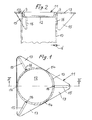
- the reference number 10 designates a part of, for example, a shipping sleeve, of which both ends are to be closed by lids, one lid being firmly attached to the shipping sleeve, for example by staples or adhesive se 10 can be connected, while the other cover is designed as a push-in cover 11, which can be inserted into the shipping sleeve 10 by clamping (FIG. 2).
- the push-in cover 11 is, for example, cup-shaped, ie it is provided with a cup-shaped part 12 which can be inserted into the shipping sleeve 10 in a suitable manner.
- the press-in cover 11 which is preferably made of plastic, has, for example, three wedge-shaped projections 13 arranged at equal intervals from one another as a roll lock for the shipping sleeve 10.
- the projections 13 are connected by connecting pieces 14 to form a circumferential flange which, for example, has the shape of an isosceles triangle. Its center coincides with the center of the cup-shaped part 12 of the push-in cover 11.
- the projections 13 and connecting pieces 14 sit on the end edge 9 at one end of the sleeve 10.
- the three protrusions 13 forming the roll lock for the shipping sleeve 10 are each stiffened by integrally formed stabilizing webs 15. These stabilizing webs 15 are arranged radially with respect to the cylindrical cup-shaped part 12 of the press-in cover 11.
- the inner edges 16 of the stabilizing webs 15 extend parallel to the main longitudinal axis of the shipping sleeve 10 and their distance from the outer periphery of the cup-shaped part 12 corresponds to the wall thickness "d" of the shipping sleeve 10, which means that the inner edges 16 of the stabilizing webs 15 when the press-in cover is inserted 11 lie against the outer circumference of the shipping sleeve 10.
- the overall height of the stabilizing webs 15 is several times greater than that of the cup-shaped part 12.
- the inner edges 16 of the stabilizing webs 15 are practically over their entire length on the outer circumference of the shipping sleeve 10 when the cover 11 is pressed in, which provides additional stability for the cantilever roll protection projections 13 means.
- the stabilizing webs 15 are, as can be seen clearly from FIG. 2, rounded at their free end and bevelled from there towards the respective projection 13. These measures facilitate the handling of the push-in cover 11 and the insertion into the shipping sleeve 10.
- the roll securing projections 13 protrude by about 30 mm beyond the outer circumference of the shipping sleeve 10.
- the roll securing projections could also be connected to form a flange which has a square or other polygonal plan in which the cup-shaped part 12 of the push-in cover is arranged symmetrically. If the press-in cover is made of sheet metal, for example, the stabilizing webs can be replaced by corresponding beads, which then take over the task of the stabilizing webs described above.
- both ends of the shipping sleeve 10 are closed by the same press-in cover 11, it is expedient that these, viewed in the axial direction of the shipping sleeve 10, are aligned with one another. In this way an optimal roll protection for the shipping sleeve 10 is achieved.
- the cup-shaped part 12 of the push-in cover 11 can also be a fully cylindrical part, since the push-in cover 11 can be pulled off from the shipping sleeve 10 by hand using the projections 13 with the stabilizing webs 15.
Landscapes
- Engineering & Computer Science (AREA)
- Mechanical Engineering (AREA)
- Rigid Containers With Two Or More Constituent Elements (AREA)
- Reduction Rolling/Reduction Stand/Operation Of Reduction Machine (AREA)
Abstract
Die Erfindung betrifft eine Hülse, insbesondere Versandhülse mit verschließbaren Enden, wobei wenigstens ein Ende durch einen vorzugsweise napfförmigen Eindrückdeckel verschließbar ist, der klemmend in die Hülse eingreift, auf dem Stirnrand am einen Ende der Hülse aufsitzt und eine Rollsicherung für die Hülse aufweist. Dabei weist der Eindrückdeckel mehrere auf dem Stirnrand am einen Ende der Hülse aufsitzende flache radiale Vorsprünge als Rollsicherung auf, die in Umfangsrichtung des Eindrückdeckels in gleichen Abständen voneinander angeordnet sind und über den Außenumfang der Hülse nach außen ragen. <IMAGE>
Description
- Die Erfindung bezieht sich auf eine Hülse, insbesondere Versandhülse mit verschließbaren Enden, wobei wenigstens ein Ende durch einen vorzugsweise napfförmigen Eindrückdeckel verschließbar ist, der klemmend in die Hülse eingreift, auf dem Stirnrand am einen Ende der Hülse aufsitzt und eine Rollsicherung für die Hülse aufweist.
- Um ein unerwünschtes Wegrollen von insbesondere Versandhülsen auf z.B. Transporteinrichtungen (Transportbänder, Transportrollen oder dgl.) oder Ladeflächen von beispielsweise Lastkraftwagen zu vermeiden, ist ein napfförmiger Eindrückdeckel für Versandhülsen bekannt, dessen umlaufender, auf dem Stirnrand des einen Endes der Hülse aufsitzender Flansch (in der Draufsicht) sechskantig ausgebildet ist. Diese Art einer Rollsicherung für Versandhülsen hat sich jedoch in der Praxis als ungenügend herausgestellt, was auch darauf zurückzuführen ist, daß der Überstand des sechskantigen Flansches über den Außenumfang der Versandhülse nur einige wenige Millimeter beträgt. Mit anderen Worten, dieser bekannte Eindrückdeckel hat seine zusätzliche Funktion als Rollsicherung für die Hülse nicht erfüllt.
- Es ist die Aufgabe der vorliegenden Erfindung, einen Eindrückdeckel für Hülsen, insbesondere Versandhülsen zu schaffen, der zugleich eine wirksame Rollsicherung für die Hülse bildet und gleichwohl einfach und preiswert ist.
- Gemäß der Erfindung wird obige Aufgabe dadurch gelöst, daß der Eindrückdeckel mehrere auf dem Stirnrand am einen Ende der Hülse aufsitzende flache radiale Vorsprünge als Rollsicherung aufweist, die in Umfangsrichtung des Eindrückdeckels in gleichen Abständen voneinander angeordnet sind und über den Außenumfang der Hülse um mindestens ca. 15 bis 35 mm nach außen ragen. Bei einer einfachsten Version genügen bereits zwei diametral einander gegenüberligende Vorsprünge, vorzugsweise werden jedoch drei um jeweils 120° voneinander beabstandete Vorsprünge am Eindrückdeckel vorgesehen. Die Form dieser radialen Vorsprünge kann praktisch beliebig sein, eine dreieckige Form wird jedoch bevorzugt. Da die Vorsprünge um eine Distanz von mindestens 15 bis 35 mm über den Außenumfang der Hülse hervorstehen, bilden sie eine zuverlässige Rollsicherung für die Hülse. Der Eindrückdeckel wird bevorzugt aus Kunststoff hergestellt, er kann jedoch auch ein Pappe- oder Blechteil sein oder aus umweltfreundlichen Stärkederivaten bestehen. Jede Hülse kann mit einem oder zwei solchen Eindrückdeckeln mit Rollsicherung bestückt werden.
- Ausgestaltungen der Erfindung gehen aus den Unteransprüchen hervor. So sind die die Rollsicherung bildenden Vorsprünge in radialer Richtung durch z.B. Stabilisierungsstege oder Sicken versteift. Diese Maßnahme wirkt einer möglichen unerwünschten Deformierung der Rollsicherungs-Vorsprünge entgegen.
- Eine bevorzugte Ausgestaltung der Erfindung ist dadurch gekennzeichnet, daß die die Rollsicherung bildenden Vorsprünge durch Verbindungsstücke zu einem umlaufenden Flansch verbunden sind, dessen Umriß einem Dreieck entspricht. Dieser dreieckige Flansch sitzt dann am einen Stirnrand der Versandhülse auf und bildet die Rollsicherung.
- Nach noch einer weiteren Ausgestaltung der Erfindung entspricht der Umriß des Flansches einem gleichschenkeligen Dreieck, dessen Mittelpunkt mit dem Mittelpunkt des napfförmigen Teils des Eindrückdeckels zusammenfällt. Diese Version ist bereits praxisbewährt und wird daher bevorzugt.
- Nach noch einer weiteren Ausgestaltung der Erfindung können die die Rollsicherung bildenden Vorsprünge durch Verbindungsstücke zu einem umlaufenden Flansch verbunden sein, der einen quadratischen Grundriß aufweist, in dem der napfförmige Teil des Eindrückdeckels symmetrisch angeordnet ist.
- Gemäß noch einer weiteren Ausgestaltung der Erfindung sind die Stabilisierungsstege in einem radialen Abstand vom napfförmigen Teil des Eindrückdeckels angeordnet, welcher der Wanddicke der Hülse entspricht. Dies bedeutet, daß sich die Rollsicherungs-Vorsprünge über die Stabilisierungsstege am Außenumfang der Hülse abstützen können, was den Vorsprüngen zusätzliche Stabilität verleiht.
- Der oben geschilderte Vorteil wird noch verstärkt, wenn sich die inneren Ränder der Stabilisierungsstege parallel zur Längsachse der Hülse erstrecken und am Außenumfang der Hülse anliegen und die Stabilisierungsstege eine größere Bauhöhe als der napfförmige Teil des Eindrückdeckels aufweisen.
- Zweckmäßig sind ferner die Stabilisierungsstege nach außen gegen die Vorsprünge abgeschrägt und an ihrem freien Ende abgerundet. Dies erleichtert die Handhabung des Eindrückdeckels sowie das Eindrücken des Deckels in die Versandhülse.
- Die Erfindung wird anschließend anhand der Zeichnung eines Ausführungsbeispiels erläutert. Es zeigen:
- Figur 1 eine Querschnittsansicht einer Versandhülse mit einem napfförmigen Eindrückdeckel in eingedrücktem Zustand von unten und
- Figur 2 eine Schnittansicht entlang der Linie 11 - 11 in Figur 1.
- Mit der Bezugszahl 10 ist ein Teil von beispielsweise einer Versandhülse bezeichnet, von der beide Enden durch Deckel zu verschließen sind, wobei der eine Deckel beispielsweise durch Heftklammern oder Kleber fest mit der Versandhülse 10 verbunden sein kann, während der andere Deckel als Eindrückdeckel 11 ausgebildet ist, welcher klemmend in die Versandhülse 10 einsetzbar ist (Fig.2). Der Eindrückdeckel 11 ist z.B. napfförmig ausgebildet, d.h., er ist mit einem napfförmigen Teil 12 versehen, welches passend in die Versandhülse 10 eingeschoben werden kann. Der Eindrückdeckel 11, welcher vorzugsweise aus Kunststoff hergestellt ist, weist beispielsweise drei in gleichen Abständen voneinander angeordnete keilförmige Vorsprünge 13 als Rollsicherung für die Versandhülse 10 auf. Die Vorsprünge 13 sind durch Verbindungsstücke 14 zu einem umlaufenden Flansch verbunden, der z.B. die Form eines gleichschenkeligen Dreiecks hat. Dessen Mittelpunkt fällt mit dem Mittelpunkt des napfförmigen Teils 12 des Eindrückdeckels 11 zusammen. Bei eingesetztem Eindrückdeckel 11 (Fig.2) sitzen die Vorsprünge 13 und Verbindungsstücke 14 auf dem Stirnrand 9 am einen Ende der Hülse 10.
- Die die Rollsicherung für die Versandhülse 10 bildenden drei Vorsprünge 13 sind jeweils durch angeformte Stabilisierungsstege 15 versteift. Diese Stabilisierungsstege 15 sind in bezug auf das zylindrische napfförmige Teil 12 des Eindrückdeckels 11 radial angeordnet. Die inneren Ränder 16 der Stabilisierungsstege 15 erstrecken sich parallel zur Haupt-Längsachse der Versandhülse 10 und ihr Abstand vom Außenumfang des napfförmigen Teils 12 entspricht der Wanddicke "d" der Versandhülse 10, was bedeutet, daß die inneren Ränder 16 der Stabilisierungsstege 15 bei eingesetztem Eindrückdeckel 11 am Außenumfang der Versandhülse 10 anliegen. Außerdem ist die Bauhöhe der Stabilisierungsstege 15 mehrfach so groß als die des napfförmigen Teils 12. Aufgrund obiger Maßnahmen liegen also die inneren Ränder 16 der Stabilisierungsstege 15 bei eingedrücktem Deckel 11 praktisch über ihre gesamte Länge am Außenumfang der Versandhülse 10 an, was zusätzliche Stabilität für die auskragenden Rollsicherungs-Vorsprünge 13 bedeutet. Die Stabilisierungsstege 15 sind, wie gut aus Fig. 2 hervorgeht, an ihrem freien Ende abgerundet und von dort gegen den jeweiligen Vorsprung 13 hin abgeschrägt. Diese Maßnahmen erleichtern die Handhabung des Eindrückdeckels 11 sowie das Einsetzen in die Versandhülse 10. Beim Ausführungsbeispiel ragen die Rollsicherungs-Vorsprünge 13 um ca. 30 mm über den Außenumfang der Versandhülse 10 hinaus.
- In Abweichung vom Ausführugnsbeispiel könnten die Rollsicherungs-Vorsprünge auch zu einem Flansch verbunden sein, der einen quadratischen oder anderen mehreckigen Grundriß aufweist, in dem der napfförmige Teil 12 des Eindrückdeckels symmetrisch angeordnet ist. Wenn der Eindrückdeckel beispielsweise aus Blech hergestellt wird, können die Stabilisierungsstege durch entsprechende Sicken ersetzt werden, welche dann die Aufgabe der oben beschriebenen Stabilisierungsstege übernehmen.
- Wenn bide Enden der Versandhülse 10 durch gleiche Eindrückdeckel 11 verschlossen werden, ist es zweckmäßig, daß diese dann, in Achsrichtung der Versandhülse 10 betrachtet, aufeinander ausgefluchtet werden. Dadurch wird eine optimale Rollsicherung für die Versandhülse 10 erreicht.
- Der napfförmige Teil 12 des Eindrückdeckels 11 kann auch ein vollzylindrisches Teil sein, denn das Abziehen des Eindrückdeckels 11 von der Versandhülse 10 kann auch über die Vorsprünge 13 mit den Stabilisierungsstegen 15 von Hand erfolgen.
Claims (8)
1. Hülse, insbesondere Versandhülse mit verschließbaren Enden, wobei wenigstens ein Ende durch einen vorzugsweise napfförmigen Eindrückdeckel verschließbar ist, der klemmend in die Hülse eingreift, auf dem Stirnrand am einen Ende der Hülse aufsitzt und eine Rollsicherung für die Hülse aufweist, dadurch gekennzeichnet, daß der Eindrückdeckel (11) mehrere auf dem Stirnrand (9) am einen Ende der Hülse (10) aufsitzende flache radiale Vorsprünge (13) als Rollsicherung aufweist, die in Umfangsrichtung des Eindrückdeckels (11) in gleichen Abständen voneinander angeordnet sind und über den Außenumfang der Hülse (10) um mindestens ca. 15 bis 35 mm nach außen ragen.
2. Hülse nach Anspruch 1, dadurch gekennzeichnet, daß die die Rollsicherung bildenden Vorsprünge (13) in radialer Richtung durch z.B. Stabilisierungsstege (15) oder Sicken versteift sind.
3. Hülse nach Anspruch 1 oder 2, dadurch gekennzeichnet, daß die die Rollsicherung bildenden Vorsprünge (13) durch Verbindungsstücke (14) zu einem umlaufenden Flansch verbunden sind, dessen Umriß einem Dreieck entspricht.
4. Hülse nach Anspruch 3, dadurch gekennzeichnet, daß der Umriß des Flansches einem gleichschenkeligen Dreieck entspricht, dessen Mittelpunkt mit dem Mittelpunkt des napfförmigen Teils (12) des Eindrückdeckels (11) zusammenfällt.
5. Hülse nach Anspruch 1 oder 2, dadurch gekennzeichnet, daß die die Rollsicherung bildenden Vorsprünge durch Verbindungsstücke zu einem umlaufenden Flansch verbunden sind, der einen quadratischen Grundriß aufweist, in dem der napfförmige Teil (12) des Eindrückdeckels symmetrisch angeordnet ist.
6. Hülse nach einem der Ansprüche 2 bis 5, dadurch gekennzeichnet, daß die Stabilisierungsstege (15) in einem radialen Abstand vom napfförmigen Teil (12) des Eindrückdekkels (11) angeordnet sind, welcher der Wanddicke (d) der Hülse (10) entspricht.
7. Hülse nach Anspruch 2 oder 6, dadurch gekennzeichnet, daß sich die inneren Ränder (16) der Stabilisierungsstege (15) parallel zur Längsachse der Hülse (10) erstrecken und am Außenumfang der Hülse (10) anliegen, und daß die Stabilisierungsstege (15) eine größere Bauhöhe als der napfförmige Teil (12) des Eindrückdeckels (11) aufweisen.
8. Hülse nach Anspruch 7, dadurch gekennzeichnet, daß die Stabilisierungsstege (15) nach außen gegen die Vorsprünge (13) abgeschrägt und an ihren freien Enden abgerundet sind.
Applications Claiming Priority (2)
| Application Number | Priority Date | Filing Date | Title |
|---|---|---|---|
| DE9217893U DE9217893U1 (de) | 1992-12-31 | 1992-12-31 | Hülse, insbesondere Versandhülse |
| DE9217893U | 1992-12-31 |
Publications (2)
| Publication Number | Publication Date |
|---|---|
| EP0604923A2 true EP0604923A2 (de) | 1994-07-06 |
| EP0604923A3 EP0604923A3 (de) | 1994-12-28 |
Family
ID=6887720
Family Applications (1)
| Application Number | Title | Priority Date | Filing Date |
|---|---|---|---|
| EP93120848A Withdrawn EP0604923A3 (de) | 1992-12-31 | 1993-12-23 | Hülse, insbesondere Versandhülse. |
Country Status (2)
| Country | Link |
|---|---|
| EP (1) | EP0604923A3 (de) |
| DE (1) | DE9217893U1 (de) |
Cited By (1)
| Publication number | Priority date | Publication date | Assignee | Title |
|---|---|---|---|---|
| GB2550165A (en) * | 2016-05-11 | 2017-11-15 | Artefekz Ltd | A postal tube end closure device |
Family Cites Families (1)
| Publication number | Priority date | Publication date | Assignee | Title |
|---|---|---|---|---|
| US5052578A (en) * | 1990-02-28 | 1991-10-01 | Goodwin William A | Closure for a shipping container |
-
1992
- 1992-12-31 DE DE9217893U patent/DE9217893U1/de not_active Expired - Lifetime
-
1993
- 1993-12-23 EP EP93120848A patent/EP0604923A3/de not_active Withdrawn
Cited By (1)
| Publication number | Priority date | Publication date | Assignee | Title |
|---|---|---|---|---|
| GB2550165A (en) * | 2016-05-11 | 2017-11-15 | Artefekz Ltd | A postal tube end closure device |
Also Published As
| Publication number | Publication date |
|---|---|
| DE9217893U1 (de) | 1993-04-08 |
| EP0604923A3 (de) | 1994-12-28 |
Similar Documents
| Publication | Publication Date | Title |
|---|---|---|
| DE2217490C3 (de) | Halterung einer schwimmend gelagerten Mutter an einem Werkstück | |
| EP0465896B1 (de) | Verbindungselement für Wellrohre und Schläuche | |
| DE69301592T2 (de) | Spannzange für Rohrkupplungen | |
| DE2919214C2 (de) | Verriegelungseinrichtung zur Sicherung der Verbindung zweier Wellen | |
| DE68904127T2 (de) | Vorrichtung zur verhinderung des loesens eines rads von einem achszapfen, auf welchem es frei rotierbar montiert ist. | |
| DE2256306A1 (de) | Spannhuelsenanordnung | |
| DE8012661U1 (de) | Freilauf | |
| DE4118577C2 (de) | Luftfeder mit einem Schlauchrollbalg aus elastomerem Werkstoff | |
| EP0604923A2 (de) | Hülse, insbesondere Versandhülse | |
| DE2709475A1 (de) | Halterung fuer kugelfoermige lager | |
| DE69804437T3 (de) | Schutzdeckel | |
| DE4111494C2 (de) | Rohrpostbüchse | |
| DE2113917A1 (de) | Befestigungselement | |
| DE4414577C2 (de) | Spule | |
| DE2850744A1 (de) | Vorrichtung und spule zum auf- und abrollen eines gurtes, z.b. eines sicherheitsgurtes | |
| DE3135695C2 (de) | Mit einem Spannband verschließbare Kunststoffdeckel-Verschlußanordnung für ein Kunststoff-Faß | |
| DE29506929U1 (de) | Zentriervorrichtung für die Dichtung einer Flanschverbindung | |
| DE29913396U1 (de) | Kolben für eine Kartusche | |
| DE9215713U1 (de) | Verschlußvorrichtung für einen Behälter mit Deckel | |
| DE8706592U1 (de) | Gebinde für Zweikomponentensysteme | |
| DE8803118U1 (de) | Axialgleitlager aus Schichtwerkstoff | |
| DE2755176C2 (de) | Reinigungsrohr | |
| DE29620053U1 (de) | Magazinband für Befestigungselemente | |
| CH687197A5 (de) | Spannring. | |
| CH669576A5 (de) |
Legal Events
| Date | Code | Title | Description |
|---|---|---|---|
| PUAI | Public reference made under article 153(3) epc to a published international application that has entered the european phase |
Free format text: ORIGINAL CODE: 0009012 |
|
| AK | Designated contracting states |
Kind code of ref document: A2 Designated state(s): AT BE CH DE DK FR GB IT LI LU NL |
|
| PUAL | Search report despatched |
Free format text: ORIGINAL CODE: 0009013 |
|
| AK | Designated contracting states |
Kind code of ref document: A3 Designated state(s): AT BE CH DE DK FR GB IT LI LU NL |
|
| STAA | Information on the status of an ep patent application or granted ep patent |
Free format text: STATUS: THE APPLICATION IS DEEMED TO BE WITHDRAWN |
|
| 18D | Application deemed to be withdrawn |
Effective date: 19950629 |