EP0604924A1 - Lampe de véhicule alimentée par micro-onde - Google Patents
Lampe de véhicule alimentée par micro-onde Download PDFInfo
- Publication number
- EP0604924A1 EP0604924A1 EP93120853A EP93120853A EP0604924A1 EP 0604924 A1 EP0604924 A1 EP 0604924A1 EP 93120853 A EP93120853 A EP 93120853A EP 93120853 A EP93120853 A EP 93120853A EP 0604924 A1 EP0604924 A1 EP 0604924A1
- Authority
- EP
- European Patent Office
- Prior art keywords
- applicator
- card
- applicator card
- brace
- lamp
- Prior art date
- Legal status (The legal status is an assumption and is not a legal conclusion. Google has not performed a legal analysis and makes no representation as to the accuracy of the status listed.)
- Granted
Links
- 230000008878 coupling Effects 0.000 claims abstract description 56
- 238000010168 coupling process Methods 0.000 claims abstract description 56
- 238000005859 coupling reaction Methods 0.000 claims abstract description 56
- 239000002184 metal Substances 0.000 claims description 13
- 229910052751 metal Inorganic materials 0.000 claims description 13
- 230000014759 maintenance of location Effects 0.000 claims description 9
- 230000033001 locomotion Effects 0.000 claims description 4
- 230000001605 fetal effect Effects 0.000 claims 1
- 230000003287 optical effect Effects 0.000 abstract description 4
- 238000000034 method Methods 0.000 description 5
- 239000002775 capsule Substances 0.000 description 4
- 239000004020 conductor Substances 0.000 description 3
- RYGMFSIKBFXOCR-UHFFFAOYSA-N Copper Chemical compound [Cu] RYGMFSIKBFXOCR-UHFFFAOYSA-N 0.000 description 2
- 230000006978 adaptation Effects 0.000 description 2
- 229910052802 copper Inorganic materials 0.000 description 2
- 239000010949 copper Substances 0.000 description 2
- 239000000463 material Substances 0.000 description 2
- 230000013011 mating Effects 0.000 description 2
- 239000002991 molded plastic Substances 0.000 description 2
- 239000004033 plastic Substances 0.000 description 2
- VYPSYNLAJGMNEJ-UHFFFAOYSA-N silicon dioxide Inorganic materials O=[Si]=O VYPSYNLAJGMNEJ-UHFFFAOYSA-N 0.000 description 2
- 229910000679 solder Inorganic materials 0.000 description 2
- 229910001369 Brass Inorganic materials 0.000 description 1
- 239000010951 brass Substances 0.000 description 1
- 239000000919 ceramic Substances 0.000 description 1
- 239000011248 coating agent Substances 0.000 description 1
- 238000000576 coating method Methods 0.000 description 1
- 239000002131 composite material Substances 0.000 description 1
- 238000001914 filtration Methods 0.000 description 1
- 239000005350 fused silica glass Substances 0.000 description 1
- 239000011521 glass Substances 0.000 description 1
- 238000000227 grinding Methods 0.000 description 1
- WABPQHHGFIMREM-UHFFFAOYSA-N lead(0) Chemical compound [Pb] WABPQHHGFIMREM-UHFFFAOYSA-N 0.000 description 1
- 238000004519 manufacturing process Methods 0.000 description 1
- 238000012986 modification Methods 0.000 description 1
- 230000004048 modification Effects 0.000 description 1
- 238000000059 patterning Methods 0.000 description 1
- 239000004417 polycarbonate Substances 0.000 description 1
- 229920000515 polycarbonate Polymers 0.000 description 1
- 230000001681 protective effect Effects 0.000 description 1
- 239000010453 quartz Substances 0.000 description 1
- 229910052594 sapphire Inorganic materials 0.000 description 1
- 239000010980 sapphire Substances 0.000 description 1
- 239000000565 sealant Substances 0.000 description 1
Images



Classifications
-
- H—ELECTRICITY
- H05—ELECTRIC TECHNIQUES NOT OTHERWISE PROVIDED FOR
- H05B—ELECTRIC HEATING; ELECTRIC LIGHT SOURCES NOT OTHERWISE PROVIDED FOR; CIRCUIT ARRANGEMENTS FOR ELECTRIC LIGHT SOURCES, IN GENERAL
- H05B41/00—Circuit arrangements or apparatus for igniting or operating discharge lamps
- H05B41/14—Circuit arrangements
- H05B41/24—Circuit arrangements in which the lamp is fed by high frequency AC, or with separate oscillator frequency
-
- H—ELECTRICITY
- H01—ELECTRIC ELEMENTS
- H01J—ELECTRIC DISCHARGE TUBES OR DISCHARGE LAMPS
- H01J65/00—Lamps without any electrode inside the vessel; Lamps with at least one main electrode outside the vessel
- H01J65/04—Lamps in which a gas filling is excited to luminesce by an external electromagnetic field or by external corpuscular radiation, e.g. for indicating plasma display panels
- H01J65/042—Lamps in which a gas filling is excited to luminesce by an external electromagnetic field or by external corpuscular radiation, e.g. for indicating plasma display panels by an external electromagnetic field
- H01J65/044—Lamps in which a gas filling is excited to luminesce by an external electromagnetic field or by external corpuscular radiation, e.g. for indicating plasma display panels by an external electromagnetic field the field being produced by a separate microwave unit
Definitions
- the invention relates to electric lamps and particularly to vehicle headlamps. More particularly the invention is concerned with a microwave powered vehicle lamp.
- the filament cannot be lit until after the housing is closed, so the beam adjustment is made by grinding exterior locators to a reference level.
- the reflector housing With capsule lamps, the reflector housing can be held in an ideal position while the lit capsule is adjusted to its proper optical position.
- the "lamp-on" adjustment method has the advantage of adjusting both the direction of the beam, and the beam pattern.
- the “lamp-on” adjustment method generally uses each lamp lead, extended through a respective metal lined eyelet hole in the reflector, to adjust the lamp position. With the lamp in position, the leads are soldered in place in the eyelets, thereby fixing the lamp position.
- the lamp assembly includes a printed circuit card that supports the discharge tube, the strip line conductors, and the microwave power applicators.
- the applicator card that prelocates the light source while allowing final, accurate adjustment.
- a structure that limits the complete freedom of the light source to a small range of freedom that is close to the desired position, while still allowing a final accurate positioning there is a need for a support structure that is compatible with a practical, industrial alignment procedure.
- a microwave vehicle lamp may be formed with a reflector housing having a rear wall defining a rearward portion of an enclosed volume, a first reflector coupling point, and a second reflector coupling point.
- a lens is mated with the reflector housing to substantially close a forward side of the enclosed volume.
- a substantially planar applicator card having microwave conductive channel for delivering microwave power, a first card coupling point, and a second card coupling point are positioned, so the first reflector coupling point and the first card coupling point are pivotally coupled, and the second reflector coupling point and second card coupling point are rigidly coupled.
- Means are also included for delivering microwave power to the applicator card, and on to at least one microwave power applicator supported by the applicator card and electrically coupled to the applicator card to receive microwave power from the applicator card, and a microwave powered light source supported from the applicator card, and positioned to receive microwave power from the microwave applicator and thereby produce light.
- FIG. 1 shows a cross sectional top view of a preferred embodiment of a microwave vehicle lamp.
- FIG. 2 shows a cross sectional side view of the microwave vehicle lamp in FIG. 1.
- the microwave vehicle lamp 10 is assembled from a reflector housing 12, an applicator card 24, a brace 30, a lens 36, and a light source 38.
- the reflector housing 12 may he made out of molded plastic to have the general form of a shell defining an enclosed volume.
- the reflector housing 12 has a rear wall 14, a first coupling point, which may be a retention slot 16, a second reflector coupling 18, and possibly an optional third reflector coupling 20.
- the rear wall 14 may include a forward facing reflective surface.
- the rear wall 14 may be a plane housing wall with a separate reflector positioned in the enclosed volume as is known in the art (not shown).
- the preferred rear wall 14 includes a reflective section of parabolic surface.
- the retention slot 16 is sized and shaped to capture and position a portion of the applicator card 24.
- the retention slot 16 may comprise a slit passage through the reflector housing 12, having a slit width and length sufficient to admit some or all of the applicator card 24.
- the preferred retention slot 16 is an open passage through the reflector housing 12, having sufficient clearance to allow the forward portion of the applicator card 24 and light source to be passed through the reflector housing 12 into the enclosed volume.
- the slot 16 is then a narrow slit formed in the reflector housing 12 to receive a portion of the applicator card 24.
- the applicator card 24 may be inserted in the slot 16 from either the rear or forward side, as may be convenient.
- the reflector housing 12 also includes a second reflector coupling 18.
- the second reflector coupling 18 comprises a mating point adaptation for coupling the reflector housing 12 to the first end of the brace 30.
- the preferred second reflector coupling 18 includes a passage in which a portion of the brace 30 may be closely, but adjustablly positioned.
- a through hole is formed in the reflector housing 12 and lined with a metal eyelet 32 having sufficient internal diameter 34 to allow a sturdy metal rod to snuggly pass through.
- the reflector housing 12 may have a second or even a third reflector coupling if needed, all of which may be similarly formed.
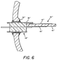
- FIG. 6 shows a cross sectional, detailed view, partially broken away, of a similar eyelet, eyelet 32'' coupling, and a similar brace, coaxial conductor brace 30'' coupled to a similar three layer applicator card 24''.
- reflector housing 12 in FIG. 1, is shown as a parabolic reflector having horizontal truncations along the top and bottom portions.
- a vertically oriented support slot 16 is located centrally through the rear axis of the reflector housing 12.
- Horizontally offset on either side of the reflector axis are two metal rivet lined eyelets 32 with through passages.
- Other suitable cross sectional configuration may be used.
- the lens 36 may be made out of glass or plastic to have the general form of a flat or curved surface mateable to the reflector housing 12 to thereby substantially close off the enclosed volume.
- the light source 38 may be made from a high temperature and light transmissive material, such as quartz or sapphire, to have the general form of a tubular capsule.
- the reflector housing 12 and lens 36 enclose the light source 38 in the enclosed volume.
- the light source 38 may be supported at either or both ends by rods formed to extend from the capsule, with the rods coupling to supports extended from the applicator card 24.
- the applicator card 24 may be made out of laminated planar card of conductive and insulative layers to have the general form of a planar card with a notched region 40.
- the reflector housing 12 encloses at least that portion of the applicator card 24 that supports the light source 38.
- the preferred applicator card 24 has a notched region 40, a conductive base plane 42 on a first side, an insulative middle layer 44, and a strip line pattern 46 layer on a second side.
- the notched region 40 may be sized so the light producing portion of the light source 38 may be generally positioned within the notched region 40.
- the preferred notched region 40 is a rectangular region whose length is longer than the enclosed volume of the light source 38, but shorter than the tip to tip length of the whole light source 38.
- the width of the preferred light source 38 is less than the width of the notched region 40.
- Positioned along applicator card 24 may be a conductive base plane 42.
- the conductive base plane 42 may be a copper layer formed on one side of the applicator card 24.
- Positioned along applicator card 24 may also be an insulative middle layer 44.
- the preferred insulative layer 44 is a stiff nonconductive planar piece of plastic, ceramic, or composite.
- Positioned on applicator card 24 on the side opposite the base plane 42 may be a stripe line pattern 46.
- the stripe line pattern 46 provides conductive microwave circuit channels for light source 38 power.
- the applicator card 24 also provides a point of attachment for a microwave power cable 48 and may include filtering components or circuit features, such as those described in US Patent No. 5,144,206.
- the applicator card 24 has a card coupling 50 for the brace 30.
- the applicator card coupling 50 comprises a mating point adaptation for coupling the applicator card 24 to the first end of the brace 30.
- the preferred applicator card 24 coupling is similar to the coupling point formed in the reflector housing 12.
- a through hole may be formed in the applicator card 24 and lined with a metal eyelet 52 having sufficient internal diameter to allow a sturdy metal rod to snuggly pass through.
- the brace 30 may be formed from the power cable 48 as shown in FIG.s 3, 4, 5, 6, 7 and 8.
- the brace 30 may be made out of metal to have the general form of a rod.
- the brace 30 has a first portion that couples to the reflector housing 12.
- a rod end may be conveniently adjusted and then soldered in metal lined passage, such as an eyelet 32.
- the brace 30 has a second portion that may be similarly coupled to the applicator card 24.
- the second rod end may then serve as the second coupling point.
- the reflector housing 12 couples at the second reflector coupling 18 to the first end of the brace 30.
- the applicator card 24 may be coupled to the second end of the brace 30.
- the rod may extend through the applicator card coupling 50 to a second reflector housing 12 coupling 20.
- the brace 30 is shown as a round rod, but rectangular, planar and similarly shaped pieces may be used. It is only necessary that the brace 30 couple between the applicator card 24 and the housing 12, and be sufficiently stiff and durable to adequately retain the reflector housing 12 and applicator card 24 in proper position with respect to each other.
- a simple U shaped wire brace 30 may be threaded through a hole in the applicator card 24 and as the applicator card 24 is advanced to its final position, the tips of the wire brace 30 are inserted into eyelet holes 18, 20 in the reflector housing.
- the eyelets hole 50 in the applicator card 24 may be surrounded by a large pad of solderable circuit board conductive coating, typically copper, to thereby receive the soldered connection.
- the applicator card 24 positions the discharge tube at a nominal focus position. Manufacturing variations of the various components, particularly of the optical surface, generally require small departures from the nominally ideal optically position to be made to focus and point the beam finally.
- Adjustments may be done by hand or by machine as is generally known. Since the applicator card 24 seesaws about a fulcrum point defined by the slot 16, adjustment motions vertically and horizontally are opposite that of the light source 38, while longitudinal motions are in the same direction. The structure then provides a structure that limits the complete freedom of the light source to a small range of freedom that is close to the desired position, while still allowing a final accurate positioning by practical, industrial alignment procedures.
- the tooling fixture for focusing and aiming the beam maintains the applicator card 24 position for a few seconds while solder is applied to the coupling points along the brace 30.
- the first point is at the center of the brace 30, where the brace 30 intersects the applicator card 24.
- the other points are at the ends of the brace 30 where the brace 30 couples with the reflector housing, 18, 20.
- a sealant may be applied along the slit to seal the passage into the reflector housing 12.
- a coaxial connector cable 48 and a protective cover may be attached to complete the assembly.
- the light source may be convenient to orient the light source transversely to the reflector axis. Transverse orientation is common in some automotive lamps where the crosswise filament forms a crosswise pattern illuminating the highway. It may also be convenient to position the applicator card entirely in the enclosed lamp volume. Internal positioning is more likely for lamps operated at higher frequency, such as the ISM band centered around 2.45 GHz. For such high frequency lamps, the applicator card may be made much smaller, scaling approximately with the inverse of frequency, thereby permitting the entire applicator card to be mounted inside the reflector housing.
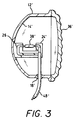
- FIG. 3 shows a cross sectional side view of a preferred alternative microwave vehicle lamp. Similar elements have been numbered correspondingly to those in FIG. 1.
- the retention slot 16 may be formed as a channel 26' on the interior side of the reflector housing 12', and positioned in the enclosed volume to capture and position an edge of the applicator card 24'.
- the channel 26' width and depth may be chosen to control the range of motion of the inserted applicator card 24' edge.
- a narrower, deeper channel 26' limits pivotation of the applicator card 24' to the plane of the channel 26' (normal to the reflector wall).
- FIG. 3 shows a cross sectional side view of a preferred alternative microwave vehicle lamp, where the applicator card 24' is captured in a vertical channel 26' running up the interior of the reflector housing rear wall 14.
- FIG. 4 shows a cross sectional top view of a preferred alternative microwave vehicle lamp, where the applicator card 24'' is captured in a horizontal channel 28'' running along the interior side wall of the reflector housing 12''.
- FIG. 5 shows a cross sectional side view of the microwave vehicle lamp in FIG. 4, showing the light source 38'' position slightly below the applicator card 24''.
- FIG. 4 shows a headlamp in cross section with the applicator card mounted entirely in the enclosed volume.
- the applicator card 24'' is positioned on the forward side of the discharge tube 38'' and in a horizontal plane. Forward positioning of the applicator card 24'' minimizes the interference of the light path from the discharge tube 38'' back to the reflector.
- the applicator card 24'' is shown with the discharge tube 38'' mounted underneath.
- the applicator card 24'' can be supported horizontally by positioning an edge of the applicator card 24'' in the horizontal channel 28'', and holding the applicator card 24'' by a coaxial microwave power cable serving also as a brace 30''.
- the brace 30'' is soldered in place after final adjustment is made to achieve the final position of the applicator card 24'' and discharge tube 38''.
- An optional second brace may be added for additional stiffness.
- FIG. 6 shows the coaxial cable 48'' attached to an edge of the applicator card 24''.
- the cable 48'' end is shaped so the outer lead is in contact with a first side of the applicator card 24'', the insulative core of the cable 48'' may be braced against the insulative core of the applicator card 24'', and the center lead is connected to a second side of the applicator card 24''.
- the inner end of the cable 48'' is cut and shaped so the outer lead can be soldered to the base plane 42'' on the upper side of the board while the center lead wire can be soldered to the strip line pattern 46'' on the lower side of the applicator card 24''.
- the coaxial cable 48'' can have a coaxial connector or length of coaxial cable crimped to it for later attachment to the microwave power input supply.
- the power coupling structure serves as the applicator card coupling.
- FIG. 7 shows a cross sectional top view of an preferred alternative embodiment of a microwave vehicle lamp.
- FIG. 8 shows a cross sectional side view of the microwave vehicle lamp in FIG. 7.
- the pivotal connection to the first coupling point 52 on the applicator card 54 may be a rod 56 coupled to a portion of the applicator card 54.
- the power cable 58 may provide the second, rigid coupling point.
- a rod 56 coupled to the first applicator coupling point may be sufficiently flexibility, that the applicator card 54 may be coupled to the rod 56 and still be pivoted enough to swing the light source 60 into proper position.
- the power cable 58 may then be soldered in place to and eyelet 62 to hold the applicator card 54, and light source 60 in the preferred optical position.
- the reflector housing was made of molded plastic, and had a retention slot, a rear wall, a second reflector coupling, with an overall width of about 10 centimeters, a length of about 16.5 centimeters, and a depth of about 6 centimeters.
- the lens was made of polycarbonate, and had a width of about 10 centimeters, a length of about 16.5 centimeters, and a thickness of abut 2 millimeters.
- the light source was made of high temperature, light transmissive material, fused silica, and had an inside diameter of about 2.0 millimeters, an outside diameter of about 3.0 millimeters, and a length of about 10 millimeters.
- the applicator card was made of laminated conductive and insulative layers, and had a notched region, a conductive base plane, a insulative middle layer, a stripe line patterning, a connector coupling, and a power coupling.
- the applicator card thickness was about 1.52 millimeters (0.06 inch).
- the brace was made of brass rod, and had a diameter of 1.52 millimeter (0.06 inch).
- the sample headlamp was self contained, and mounted in an automobile for testing. The color rendition of the light illuminating the roadway was judged to be excellent, and the beam pattern, resulting from simple focusing and adjustment of the applicator card with reference to the reflector was found to achieve adequate distribution.
- the disclosed operating conditions, dimensions, configurations and embodiments are presented as examples only, and other suitable configurations and relations may be used to implement the invention.
Landscapes
- Physics & Mathematics (AREA)
- Electromagnetism (AREA)
- Engineering & Computer Science (AREA)
- Plasma & Fusion (AREA)
- Non-Portable Lighting Devices Or Systems Thereof (AREA)
Applications Claiming Priority (2)
| Application Number | Priority Date | Filing Date | Title |
|---|---|---|---|
| US07/997,821 US5299100A (en) | 1992-12-29 | 1992-12-29 | Microwave powered vehicle lamp |
| US997821 | 1992-12-29 |
Publications (2)
| Publication Number | Publication Date |
|---|---|
| EP0604924A1 true EP0604924A1 (fr) | 1994-07-06 |
| EP0604924B1 EP0604924B1 (fr) | 1999-04-21 |
Family
ID=25544435
Family Applications (1)
| Application Number | Title | Priority Date | Filing Date |
|---|---|---|---|
| EP93120853A Expired - Lifetime EP0604924B1 (fr) | 1992-12-29 | 1993-12-23 | Lampe de véhicule alimentée par micro-onde |
Country Status (4)
| Country | Link |
|---|---|
| US (1) | US5299100A (fr) |
| EP (1) | EP0604924B1 (fr) |
| CA (1) | CA2112321A1 (fr) |
| DE (1) | DE69324558T2 (fr) |
Families Citing this family (8)
| Publication number | Priority date | Publication date | Assignee | Title |
|---|---|---|---|---|
| US5378449A (en) * | 1993-08-31 | 1995-01-03 | The United States Of America As Represented By The Secretary Of The Air Force | Formation of basic hydrogen peroxide |
| JPH0723342U (ja) * | 1993-10-01 | 1995-04-25 | 旭光学工業株式会社 | カメラのストロボ装置 |
| US5821698A (en) * | 1996-06-26 | 1998-10-13 | Osram Sylvania Inc. | Refractory block for supporting electrodeless lamp capsule |
| US6179448B1 (en) | 1998-02-18 | 2001-01-30 | Micron Technology, Inc. | Automated light tuner |
| US6107752A (en) * | 1998-03-03 | 2000-08-22 | Osram Sylvania Inc. | Coaxial applicators for electrodeless high intensity discharge lamps |
| JP2007515039A (ja) * | 2003-08-01 | 2007-06-07 | コーニンクレッカ フィリップス エレクトロニクス エヌ ヴィ | 照明器具及び照明器具を製造する方法 |
| GB2468580A (en) * | 2009-03-10 | 2010-09-15 | Osram Ges Mit Beschrankter | Electrodeless high pressure discharge lamp with cage wire support structure |
| GB2472486A (en) * | 2009-07-30 | 2011-02-09 | Osram Gmbh | Electrodeless high pressure discharge lamp with cage wire support structure |
Citations (3)
| Publication number | Priority date | Publication date | Assignee | Title |
|---|---|---|---|---|
| EP0457242A1 (fr) * | 1990-05-15 | 1991-11-21 | Osram Sylvania Inc. | Lampe de décharge à haute intensité sans électrode avec coupleur à raccorder à un générateur à micro-ondes |
| US5130612A (en) * | 1991-09-11 | 1992-07-14 | Gte Products Corporation | Loop applicator for high frequency electrodeless lamps |
| US5144206A (en) * | 1991-09-10 | 1992-09-01 | Gte Products Corporation | Electrodeless HID lamp coupling structure with integral matching network |
Family Cites Families (2)
| Publication number | Priority date | Publication date | Assignee | Title |
|---|---|---|---|---|
| US5070277A (en) * | 1990-05-15 | 1991-12-03 | Gte Laboratories Incorporated | Electrodless hid lamp with microwave power coupler |
| US5113121A (en) * | 1990-05-15 | 1992-05-12 | Gte Laboratories Incorporated | Electrodeless HID lamp with lamp capsule |
-
1992
- 1992-12-29 US US07/997,821 patent/US5299100A/en not_active Expired - Lifetime
-
1993
- 1993-12-23 EP EP93120853A patent/EP0604924B1/fr not_active Expired - Lifetime
- 1993-12-23 DE DE69324558T patent/DE69324558T2/de not_active Expired - Fee Related
- 1993-12-23 CA CA002112321A patent/CA2112321A1/fr not_active Abandoned
Patent Citations (3)
| Publication number | Priority date | Publication date | Assignee | Title |
|---|---|---|---|---|
| EP0457242A1 (fr) * | 1990-05-15 | 1991-11-21 | Osram Sylvania Inc. | Lampe de décharge à haute intensité sans électrode avec coupleur à raccorder à un générateur à micro-ondes |
| US5144206A (en) * | 1991-09-10 | 1992-09-01 | Gte Products Corporation | Electrodeless HID lamp coupling structure with integral matching network |
| US5130612A (en) * | 1991-09-11 | 1992-07-14 | Gte Products Corporation | Loop applicator for high frequency electrodeless lamps |
Also Published As
| Publication number | Publication date |
|---|---|
| US5299100A (en) | 1994-03-29 |
| DE69324558T2 (de) | 1999-12-23 |
| CA2112321A1 (fr) | 1994-06-30 |
| DE69324558D1 (de) | 1999-05-27 |
| EP0604924B1 (fr) | 1999-04-21 |
Similar Documents
| Publication | Publication Date | Title |
|---|---|---|
| CA2042251C (fr) | Lampe hid sans electrode munie d'un connecteur hyperfrequences | |
| US5070277A (en) | Electrodless hid lamp with microwave power coupler | |
| EP0111426B1 (fr) | Dispositif d'éclairage pour pare-soleil | |
| JP3920486B2 (ja) | 車両用灯具 | |
| US6007222A (en) | Modular exterior rearview mirror assembly | |
| US6336737B1 (en) | Modular exterior rearview mirror assembly | |
| EP0374846A2 (fr) | Phare automobile avec lampe à décharge | |
| US5299100A (en) | Microwave powered vehicle lamp | |
| JPS60258802A (ja) | 自動車両用照明装置 | |
| CA2048797A1 (fr) | Ampoule jetable pour phare d'automobile | |
| EP0282751A2 (fr) | Bloc-projecteur pour automobiles | |
| EP0457242B1 (fr) | Lampe de décharge à haute intensité sans électrode avec coupleur à raccorder à un générateur à micro-ondes | |
| US5627428A (en) | Single-based high-pressure discharge lamp particularly for automotive-type headlights | |
| JPS63150801A (ja) | 自動車のヘツドライトユニツト | |
| JPH02172156A (ja) | 車両用ヘッドライトランプ及びその製造方法 | |
| US4612475A (en) | Increased efficacy arc tube for a high intensity discharge lamp | |
| US4429249A (en) | Sealed beam lamp and method of manufacture | |
| JPH09180687A (ja) | 白熱電球及びその製造方法並びに減光フード | |
| US6203392B1 (en) | Single ended quartz projection lamp | |
| JPH0853028A (ja) | 光源とその組立て方法 | |
| US4171497A (en) | Sealed beam lamp for automobile | |
| US4363994A (en) | Halogen lamp with strap-type bulb support mechanism | |
| GB2071410A (en) | Sealed Beam Lamp and Method of Manufacture | |
| US6653764B2 (en) | Discharge bulb and method of manufacturing the same | |
| EP1188984B1 (fr) | Source de lumière de dispositif d' éclairage pour véhicule |
Legal Events
| Date | Code | Title | Description |
|---|---|---|---|
| PUAI | Public reference made under article 153(3) epc to a published international application that has entered the european phase |
Free format text: ORIGINAL CODE: 0009012 |
|
| 17P | Request for examination filed |
Effective date: 19940119 |
|
| AK | Designated contracting states |
Kind code of ref document: A1 Designated state(s): DE FR |
|
| 17Q | First examination report despatched |
Effective date: 19950630 |
|
| RAP1 | Party data changed (applicant data changed or rights of an application transferred) |
Owner name: OSRAM SYLVANIA INC. |
|
| GRAG | Despatch of communication of intention to grant |
Free format text: ORIGINAL CODE: EPIDOS AGRA |
|
| GRAG | Despatch of communication of intention to grant |
Free format text: ORIGINAL CODE: EPIDOS AGRA |
|
| GRAH | Despatch of communication of intention to grant a patent |
Free format text: ORIGINAL CODE: EPIDOS IGRA |
|
| GRAH | Despatch of communication of intention to grant a patent |
Free format text: ORIGINAL CODE: EPIDOS IGRA |
|
| GRAA | (expected) grant |
Free format text: ORIGINAL CODE: 0009210 |
|
| AK | Designated contracting states |
Kind code of ref document: B1 Designated state(s): DE FR |
|
| REF | Corresponds to: |
Ref document number: 69324558 Country of ref document: DE Date of ref document: 19990527 |
|
| ET | Fr: translation filed | ||
| PLBE | No opposition filed within time limit |
Free format text: ORIGINAL CODE: 0009261 |
|
| STAA | Information on the status of an ep patent application or granted ep patent |
Free format text: STATUS: NO OPPOSITION FILED WITHIN TIME LIMIT |
|
| 26N | No opposition filed | ||
| PGFP | Annual fee paid to national office [announced via postgrant information from national office to epo] |
Ref country code: FR Payment date: 20011130 Year of fee payment: 9 |
|
| PGFP | Annual fee paid to national office [announced via postgrant information from national office to epo] |
Ref country code: DE Payment date: 20011204 Year of fee payment: 9 |
|
| PG25 | Lapsed in a contracting state [announced via postgrant information from national office to epo] |
Ref country code: DE Free format text: LAPSE BECAUSE OF NON-PAYMENT OF DUE FEES Effective date: 20030701 |
|
| PG25 | Lapsed in a contracting state [announced via postgrant information from national office to epo] |
Ref country code: FR Free format text: LAPSE BECAUSE OF NON-PAYMENT OF DUE FEES Effective date: 20030901 |
|
| REG | Reference to a national code |
Ref country code: FR Ref legal event code: ST |