EP0604935A1 - Leistungskompensierte Kopplungsanordnung für elektrodenlose Entladungslampe - Google Patents
Leistungskompensierte Kopplungsanordnung für elektrodenlose Entladungslampe Download PDFInfo
- Publication number
- EP0604935A1 EP0604935A1 EP93120916A EP93120916A EP0604935A1 EP 0604935 A1 EP0604935 A1 EP 0604935A1 EP 93120916 A EP93120916 A EP 93120916A EP 93120916 A EP93120916 A EP 93120916A EP 0604935 A1 EP0604935 A1 EP 0604935A1
- Authority
- EP
- European Patent Office
- Prior art keywords
- transmission line
- line
- lamp
- power
- electrical length
- Prior art date
- Legal status (The legal status is an assumption and is not a legal conclusion. Google has not performed a legal analysis and makes no representation as to the accuracy of the status listed.)
- Granted
Links
- 230000008878 coupling Effects 0.000 title claims abstract description 16
- 238000010168 coupling process Methods 0.000 title claims abstract description 16
- 238000005859 coupling reaction Methods 0.000 title claims abstract description 16
- 230000005540 biological transmission Effects 0.000 claims abstract description 62
- 239000002775 capsule Substances 0.000 claims abstract description 24
- 230000005670 electromagnetic radiation Effects 0.000 claims description 2
- 239000000463 material Substances 0.000 claims description 2
- 238000000059 patterning Methods 0.000 description 4
- 238000010586 diagram Methods 0.000 description 2
- 239000002019 doping agent Substances 0.000 description 2
- 230000009977 dual effect Effects 0.000 description 2
- 230000005284 excitation Effects 0.000 description 2
- 239000007789 gas Substances 0.000 description 2
- 238000000034 method Methods 0.000 description 2
- 239000000126 substance Substances 0.000 description 2
- 239000004020 conductor Substances 0.000 description 1
- 230000003111 delayed effect Effects 0.000 description 1
- 238000010438 heat treatment Methods 0.000 description 1
- 239000000203 mixture Substances 0.000 description 1
- 238000012986 modification Methods 0.000 description 1
- 230000004048 modification Effects 0.000 description 1
- 230000003287 optical effect Effects 0.000 description 1
- 230000000149 penetrating effect Effects 0.000 description 1
- 239000010453 quartz Substances 0.000 description 1
- 230000005855 radiation Effects 0.000 description 1
- 230000003014 reinforcing effect Effects 0.000 description 1
- VYPSYNLAJGMNEJ-UHFFFAOYSA-N silicon dioxide Inorganic materials O=[Si]=O VYPSYNLAJGMNEJ-UHFFFAOYSA-N 0.000 description 1
Images

Classifications
-
- H—ELECTRICITY
- H05—ELECTRIC TECHNIQUES NOT OTHERWISE PROVIDED FOR
- H05B—ELECTRIC HEATING; ELECTRIC LIGHT SOURCES NOT OTHERWISE PROVIDED FOR; CIRCUIT ARRANGEMENTS FOR ELECTRIC LIGHT SOURCES, IN GENERAL
- H05B41/00—Circuit arrangements or apparatus for igniting or operating discharge lamps
- H05B41/14—Circuit arrangements
- H05B41/24—Circuit arrangements in which the lamp is fed by high frequency AC, or with separate oscillator frequency
-
- H—ELECTRICITY
- H01—ELECTRIC ELEMENTS
- H01J—ELECTRIC DISCHARGE TUBES OR DISCHARGE LAMPS
- H01J65/00—Lamps without any electrode inside the vessel; Lamps with at least one main electrode outside the vessel
- H01J65/04—Lamps in which a gas filling is excited to luminesce by an external electromagnetic field or by external corpuscular radiation, e.g. for indicating plasma display panels
- H01J65/042—Lamps in which a gas filling is excited to luminesce by an external electromagnetic field or by external corpuscular radiation, e.g. for indicating plasma display panels by an external electromagnetic field
- H01J65/044—Lamps in which a gas filling is excited to luminesce by an external electromagnetic field or by external corpuscular radiation, e.g. for indicating plasma display panels by an external electromagnetic field the field being produced by a separate microwave unit
Definitions
- the invention relates to electric lamps and particularly to discharge lamps. More particularly the invention is concerned with electrodeless discharge lamps.
- Microwave power may be used to power a high intensity discharge.
- the lamp typically comprises a quartz capsule containing an excitable set of gases and chemical dopants. Microwave radiation is then directed at the capsule, causing the fill materials to heat to a plasma state and emit light.
- the discharge may have high intensity, and because there are no electrodes penetrating the capsule wall, the lamps are referred to as electrodeless high intensity discharge lamps, or electrodeless HID lamps.
- Microwave electrodeless HID lamps in the past have been coupled to power sources using termination fixtures which were typically large, bulky shielded coaxial structures.
- the heavy shielded structures are conceptually similar to microwave ovens.
- the heavy shielding has been an incumberance to the efficient capture and display of the emitted light.
- a novel dual ended excitation scheme was disclosed by Lapatovich in U.S. 5,070,277. Strip line conductors were coupled to microwave applicators directed at a tubular capsule. Microwave applicators that have been used with tubular capsules include slow wave helices, end cups, loop applicators and so forth.
- the dual ended excitation scheme provides substantial flexibility with respect to impedance matching techniques compared with the older termination fixture techniques. Considerable reduction in size and weight of the microwave coupler was achieved. With the reduced size of the applicator, more of the emitted light could be used in an optical system.
- the coil coupling and strip line patterning structures required an external variable impedance matching means, which can be bulky and expensive. There is then a need for a microwave circuit pattern for electrodeless lamps having balanced power distribution.
- An electrodeless lamp having a power balanced coupling structure may be formed to receive microwave power having an operating frequency, through an input line.
- the received power is divided between a first transmission line, having a first electrical length and coupling at a first junction, and a second transmission line, having a second electrical length and coupling at a second junction, wherein the differential electrical length between the first transmission line and the electrical length of the second transmission line is an odd number of half wave lengths of the operating frequency.
- a strap line couples between the first junction and the second junction and has a third electrical length being an odd multiple of half wavelengths of the operating frequency.
- a first applicator couples at the first junction to received microwave power from the first transmission line
- a second applicator couples at the second junction to received microwave power from the second transmission line
- a discharge capsule receives microwave power from the first applicator, and the second applicator to emit electromagnetic radiation.
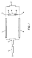
- FIG. 1 shows a schematic diagram of a preferred embodiment of a power balanced coupling structure for an electrodeless discharge lamp.
- FIG. 2 shows a perspective view a preferred embodiment of a power balanced coupling structure for an electrodeless discharge lamp.
- FIG. 1 shows a schematic diagram of a preferred embodiment of a power balanced coupling structure for an electrodeless discharge lamp.
- the power balanced coupling circuit for electrodeless discharge lamp may be assembled from microwave power delivery channels, such as strip line patternings.
- the circuit includes an input line 10, a first transmission line 14, a second transmission line 18, and a strap line 22.
- strip line components are executed on a circuit board having the strip line pattern on a first side, an insulative intermediate layer, and a conductive base plane on a second side.
- FIG. 2 shows a perspective view a preferred embodiment of a power balanced coupling structure for an electrodeless discharge lamp.
- the embodiment is implemented on a laminated card having a strip line patterning 30 on one side, an intermediate insulating layer 32, and a conductive base plane 34 on an opposite side.
- the card includes a notched region 36 where a tubular discharge capsule is positioned between two helical microwave applicators.
- the circuit features of FIG. 1. are noted with the primed numberings.
- the input line 10 receives power from a microwave input source.
- the received power typically has a frequency permitted under the ISM bands, such as 915 MHz, or 2.45 GHZ. Other appropriate ISM bands may be used as are permitted. Technically, still further frequencies could be used.
- the input line 10 maybe a coaxial cable, or a strip line connection formed on a laminated card.
- the preferred embodiment is a coaxial cable connector having one lead coupled to a strip line pattern ending at a T connection 12.
- the second coaxial cable lead is coupled to the base plane.
- the input line 10 ends at a power divider, such as a T connection 12.
- the power divider proportions the supplied power between the first transmission line 14 and the second transmission line 18.
- T connection 12 When a T connection 12 is used, about half the original power is delivered to the first transmission line 14, and half the power is delivered to the second transmission line 18.
- the first transmission line 14 is preferably a strip line pattern formed on a laminated card. One side of the card has the strip line patterning formed on an intermediate insulative layer, and on the opposite side of the intermediate insulative layer is a conductive base plane.
- the first transmission line 14 extends from the T connection 12 to a first junction 16 with first microwave applicator 24, such as a wire coil. The first transmission line 14 then supplies power to the first applicator 24 coil.
- the second transmission line 18 may be similarly formed strip line pattern on a laminated card.
- the second transmission line 18 extends from the T connection 12 to a second junction 20 with a second microwave applicator 26, such as a wire coil.
- the second transmission line 18's length is preferably the same length as first transmission line 14 plus an odd number of half wavelengths of the microwave power delivered.
- the second transmission line 18 then supplies delayed power to the second applicator 26 coil.
- the differential electrical length of the first transmission line 14 and the second transmission line 18 is important.
- the differential length should be an odd number of half wavelengths at the operating frequency.
- the preferred differential electrical length is just one half wave length, however, in applications where a larger differential electrical length is needed or desired, a longer length may be used.
- the characteristic impedance of the microwave power transmissions lines, the electrical length of the first transmission line 14, and the electrical length of the second transmission line 18 may be tailored to provide impedance matching between the discharge capsule 28 and the microwave power source.
- the strap line 22 may be a similarly formed strip line pattern on a laminated card.
- the strap line 22 extends from the first junction 16 between the first transmission line 14 and the first applicator 24 coil to the second junction 20 between the second transmission line 18 and the second applicator 26 coil.
- the strap line 22's electrical length is preferably an odd number of half wavelengths of the microwave power delivered.
- the strap line 22 acts to suppress the unbalanced power delivery to the first applicator 24, the second applicator 26 and the discharge capsule 28.
- the strap line 22 then helps balance the power between the first applicator 24 coil and the second applicator 26 coil, by reinforcing odd mode currents and canceling even mode currents.
- the strap line 22 then reinforces the balanced current components and cancels the unbalanced current components flowing to the applicators 24, 26 and discharge capsule 28. While a quarter wave transformer line is disclosed, other combinations of cascaded transmission line sections with the prescribed characteristic impedance may be used to provide impedance matching.
- the first applicator 24 coil and the second applicator 26 coil may be wire helixes positioned coaxially with discharge capsule 28.
- the discharge capsule 28 may be a tubular capsule enclosing a microwave power excitable mixture of gases and chemical dopants as known in the art.
- the discharge capsule 28 may be suspended at one or both of its axial ends by mechanical supports as is known in the art.
- the microstrip transmission lines at the output of the T connection 12 had a characteristic impedance of 70.7 ohms.
- the electrical length of the first transmission line was one quarter wave length, while the electrical length of the second transmission line was three quarters wave length, giving a differential length of one half wave length.
- the half wave length strap line also had a characteristic impedance of 70.7 ohms.
- the arrangement provided good impedance matching to two helical couplers, and the discharge capsule, which had a steady state impedance of approximately 100 ohms (real) at 915 MHz.
- typical 915 MHz return loss performance is approximately to 20 dB at 50 watts input power, and a luminous output of about 6000 lumens. This yields about 120 lumens per watt.
- Tests indicate that a temperature difference of as much as 218 degrees Celsius can exist between the ends of the discharge capsule in an unbalanced power lamp. With the power balancing strap line in place, a worst case test indicated that temperature difference between the discharge capsule ends was only 12 degrees Celsius. Normal operation, resulted in no detected temperature difference between the discharge capsule ends.
- the disclosed dimensions, configurations and embodiments are as examples only, and other suitable configurations and relations may be used to implement the invention.
Landscapes
- Physics & Mathematics (AREA)
- Electromagnetism (AREA)
- Engineering & Computer Science (AREA)
- Plasma & Fusion (AREA)
- Discharge Lamps And Accessories Thereof (AREA)
- Circuit Arrangements For Discharge Lamps (AREA)
Applications Claiming Priority (2)
| Application Number | Priority Date | Filing Date | Title |
|---|---|---|---|
| US999636 | 1992-12-31 | ||
| US07/999,636 US5313144A (en) | 1992-12-31 | 1992-12-31 | Power balanced coupling structure for electrodeless discharge lamp |
Publications (2)
| Publication Number | Publication Date |
|---|---|
| EP0604935A1 true EP0604935A1 (de) | 1994-07-06 |
| EP0604935B1 EP0604935B1 (de) | 1996-05-29 |
Family
ID=25546561
Family Applications (1)
| Application Number | Title | Priority Date | Filing Date |
|---|---|---|---|
| EP93120916A Expired - Lifetime EP0604935B1 (de) | 1992-12-31 | 1993-12-27 | Leistungskompensierte Kopplungsanordnung für elektrodenlose Entladungslampe |
Country Status (5)
| Country | Link |
|---|---|
| US (1) | US5313144A (de) |
| EP (1) | EP0604935B1 (de) |
| JP (1) | JPH0757702A (de) |
| CA (1) | CA2112322C (de) |
| DE (1) | DE69302891T2 (de) |
Families Citing this family (6)
| Publication number | Priority date | Publication date | Assignee | Title |
|---|---|---|---|---|
| US5373217A (en) * | 1993-03-24 | 1994-12-13 | Osram Sylvania Inc. | Method and circuit for enhancing stability during dimming of electrodeless hid lamp |
| US5498928A (en) * | 1994-05-24 | 1996-03-12 | Osram Sylvania Inc. | Electrodeless high intensity discharge lamp energized by a rotating electric field |
| JP2006128075A (ja) * | 2004-10-01 | 2006-05-18 | Seiko Epson Corp | 高周波加熱装置、半導体製造装置および光源装置 |
| JP2008140576A (ja) * | 2006-11-30 | 2008-06-19 | Seiko Epson Corp | ランプ、発光装置及びプロジェクタ |
| GB2469187A (en) * | 2009-04-01 | 2010-10-06 | Osram Ges Mit Beschrankter | An electrodeless high intensity discharge lamp |
| CN101932184A (zh) * | 2009-12-10 | 2010-12-29 | 常州菲尔普照明电器有限公司 | 一种带远程驱动模块的无极灯镇流系统 |
Citations (3)
| Publication number | Priority date | Publication date | Assignee | Title |
|---|---|---|---|---|
| EP0450131A1 (de) * | 1990-04-06 | 1991-10-09 | New Japan Radio Co., Ltd. | Elektrodenloses, durch Mikrowellen erregtes Strahlungsgerät |
| EP0457242A1 (de) * | 1990-05-15 | 1991-11-21 | Osram Sylvania Inc. | Elektrodenlose Entladungslampe höherer Intensität mit Koppler für ihren Anschluss an einen Mikrowellengenerator |
| US5144206A (en) * | 1991-09-10 | 1992-09-01 | Gte Products Corporation | Electrodeless HID lamp coupling structure with integral matching network |
Family Cites Families (2)
| Publication number | Priority date | Publication date | Assignee | Title |
|---|---|---|---|---|
| US5113121A (en) * | 1990-05-15 | 1992-05-12 | Gte Laboratories Incorporated | Electrodeless HID lamp with lamp capsule |
| US5241246A (en) * | 1991-09-10 | 1993-08-31 | Gte Laboratories Incorporated | End cup applicators for high frequency electrodeless lamps |
-
1992
- 1992-12-31 US US07/999,636 patent/US5313144A/en not_active Expired - Lifetime
-
1993
- 1993-12-23 CA CA002112322A patent/CA2112322C/en not_active Expired - Fee Related
- 1993-12-27 EP EP93120916A patent/EP0604935B1/de not_active Expired - Lifetime
- 1993-12-27 DE DE69302891T patent/DE69302891T2/de not_active Expired - Lifetime
- 1993-12-28 JP JP5349506A patent/JPH0757702A/ja not_active Withdrawn
Patent Citations (3)
| Publication number | Priority date | Publication date | Assignee | Title |
|---|---|---|---|---|
| EP0450131A1 (de) * | 1990-04-06 | 1991-10-09 | New Japan Radio Co., Ltd. | Elektrodenloses, durch Mikrowellen erregtes Strahlungsgerät |
| EP0457242A1 (de) * | 1990-05-15 | 1991-11-21 | Osram Sylvania Inc. | Elektrodenlose Entladungslampe höherer Intensität mit Koppler für ihren Anschluss an einen Mikrowellengenerator |
| US5144206A (en) * | 1991-09-10 | 1992-09-01 | Gte Products Corporation | Electrodeless HID lamp coupling structure with integral matching network |
Also Published As
| Publication number | Publication date |
|---|---|
| DE69302891T2 (de) | 1997-01-30 |
| CA2112322A1 (en) | 1994-07-01 |
| CA2112322C (en) | 2002-03-26 |
| US5313144A (en) | 1994-05-17 |
| DE69302891D1 (de) | 1996-07-04 |
| JPH0757702A (ja) | 1995-03-03 |
| EP0604935B1 (de) | 1996-05-29 |
Similar Documents
| Publication | Publication Date | Title |
|---|---|---|
| US4266162A (en) | Electromagnetic discharge apparatus with double-ended power coupling | |
| US4042850A (en) | Microwave generated radiation apparatus | |
| US3943404A (en) | Helical coupler for use in an electrodeless light source | |
| US4189661A (en) | Electrodeless fluorescent light source | |
| EP0030593B1 (de) | Kompakte fluoreszierende Lichtquelle und Verfahren zur Erregung dieser Quelle | |
| EP0593311B1 (de) | Fluoreszenzlampe | |
| CA1149078A (en) | Compact fluorescent light source having metallized electrodes | |
| WO1995023426A1 (en) | Compact microwave source for exciting electrodeless lamps | |
| RU2000130711A (ru) | Микроволновый аппликатор и способ размещения датчика температуры на микроволновом волноводе | |
| CA2076814C (en) | Electrodeless hid lamp coupling structure with integral matching network | |
| EP0604935B1 (de) | Leistungskompensierte Kopplungsanordnung für elektrodenlose Entladungslampe | |
| US6107752A (en) | Coaxial applicators for electrodeless high intensity discharge lamps | |
| CA2104093C (en) | Apparatus for coupling energy to electrodeless lamp applicators | |
| KR102267544B1 (ko) | 마이크로파 시스템 | |
| US5339008A (en) | Electromagnetic discharge appartus with dual power amplifiers | |
| KR102383781B1 (ko) | 마이크로파 시스템 | |
| US5359264A (en) | Integral impedance matching structure for electrodeless discharge lamp | |
| CA2208881C (en) | Refractory block for supporting electrodeless lamp capsule | |
| US11705321B2 (en) | Electrodeless plasma lamps, transmission lines and radio frequency systems | |
| US2868978A (en) | Test apparatus | |
| US4712046A (en) | Quadrature-coupled microwave electrodeless lamp | |
| JP2004087434A (ja) | 無電極放電ランプ光源装置 | |
| KR102470220B1 (ko) | 마이크로파 시스템 | |
| KR20200021066A (ko) | 마이크로파 시스템 | |
| US8247988B2 (en) | Compact delay line structures for field applicators for operation of electrodeless gas discharge lamps |
Legal Events
| Date | Code | Title | Description |
|---|---|---|---|
| PUAI | Public reference made under article 153(3) epc to a published international application that has entered the european phase |
Free format text: ORIGINAL CODE: 0009012 |
|
| 17P | Request for examination filed |
Effective date: 19940121 |
|
| AK | Designated contracting states |
Kind code of ref document: A1 Designated state(s): DE FR |
|
| 17Q | First examination report despatched |
Effective date: 19950705 |
|
| GRAH | Despatch of communication of intention to grant a patent |
Free format text: ORIGINAL CODE: EPIDOS IGRA |
|
| GRAA | (expected) grant |
Free format text: ORIGINAL CODE: 0009210 |
|
| AK | Designated contracting states |
Kind code of ref document: B1 Designated state(s): DE FR |
|
| REF | Corresponds to: |
Ref document number: 69302891 Country of ref document: DE Date of ref document: 19960704 |
|
| ET | Fr: translation filed | ||
| PLBE | No opposition filed within time limit |
Free format text: ORIGINAL CODE: 0009261 |
|
| STAA | Information on the status of an ep patent application or granted ep patent |
Free format text: STATUS: NO OPPOSITION FILED WITHIN TIME LIMIT |
|
| 26N | No opposition filed | ||
| PGFP | Annual fee paid to national office [announced via postgrant information from national office to epo] |
Ref country code: DE Payment date: 20121220 Year of fee payment: 20 Ref country code: FR Payment date: 20130130 Year of fee payment: 20 |
|
| REG | Reference to a national code |
Ref country code: DE Ref legal event code: R071 Ref document number: 69302891 Country of ref document: DE |
|
| PG25 | Lapsed in a contracting state [announced via postgrant information from national office to epo] |
Ref country code: DE Free format text: LAPSE BECAUSE OF EXPIRATION OF PROTECTION Effective date: 20131228 |