EP0604985A1 - Commande électromagnétique de commutateur - Google Patents
Commande électromagnétique de commutateur Download PDFInfo
- Publication number
- EP0604985A1 EP0604985A1 EP93121025A EP93121025A EP0604985A1 EP 0604985 A1 EP0604985 A1 EP 0604985A1 EP 93121025 A EP93121025 A EP 93121025A EP 93121025 A EP93121025 A EP 93121025A EP 0604985 A1 EP0604985 A1 EP 0604985A1
- Authority
- EP
- European Patent Office
- Prior art keywords
- switching
- bridge
- switch
- carrier module
- drive according
- Prior art date
- Legal status (The legal status is an assumption and is not a legal conclusion. Google has not performed a legal analysis and makes no representation as to the accuracy of the status listed.)
- Granted
Links
- 238000005192 partition Methods 0.000 claims description 19
- 238000003780 insertion Methods 0.000 claims description 7
- 230000037431 insertion Effects 0.000 claims description 7
- 238000004804 winding Methods 0.000 claims description 5
- 230000006835 compression Effects 0.000 claims description 4
- 238000007906 compression Methods 0.000 claims description 4
- 239000011810 insulating material Substances 0.000 claims description 2
- 239000000969 carrier Substances 0.000 description 4
- 238000002347 injection Methods 0.000 description 3
- 239000007924 injection Substances 0.000 description 3
- 238000004519 manufacturing process Methods 0.000 description 3
- 229920001169 thermoplastic Polymers 0.000 description 3
- 239000004416 thermosoftening plastic Substances 0.000 description 3
- 238000004873 anchoring Methods 0.000 description 2
- 239000004033 plastic Substances 0.000 description 2
- 230000000712 assembly Effects 0.000 description 1
- 238000000429 assembly Methods 0.000 description 1
- 238000010276 construction Methods 0.000 description 1
- 238000011161 development Methods 0.000 description 1
- 230000018109 developmental process Effects 0.000 description 1
- 238000010304 firing Methods 0.000 description 1
- 238000001746 injection moulding Methods 0.000 description 1
- 230000001681 protective effect Effects 0.000 description 1
- 239000012815 thermoplastic material Substances 0.000 description 1
- 238000011144 upstream manufacturing Methods 0.000 description 1
- 238000003466 welding Methods 0.000 description 1
Images






Classifications
-
- H—ELECTRICITY
- H01—ELECTRIC ELEMENTS
- H01H—ELECTRIC SWITCHES; RELAYS; SELECTORS; EMERGENCY PROTECTIVE DEVICES
- H01H1/00—Contacts
- H01H1/12—Contacts characterised by the manner in which co-operating contacts engage
- H01H1/14—Contacts characterised by the manner in which co-operating contacts engage by abutting
- H01H1/20—Bridging contacts
- H01H1/2008—Facilitate mounting or replacing contact bridge and pressure spring on carrier
-
- H—ELECTRICITY
- H01—ELECTRIC ELEMENTS
- H01H—ELECTRIC SWITCHES; RELAYS; SELECTORS; EMERGENCY PROTECTIVE DEVICES
- H01H50/00—Details of electromagnetic relays
- H01H50/02—Bases; Casings; Covers
- H01H50/04—Mounting complete relay or separate parts of relay on a base or inside a case
- H01H50/041—Details concerning assembly of relays
- H01H50/042—Different parts are assembled by insertion without extra mounting facilities like screws, in an isolated mounting part, e.g. stack mounting on a coil-support
-
- H—ELECTRICITY
- H01—ELECTRIC ELEMENTS
- H01H—ELECTRIC SWITCHES; RELAYS; SELECTORS; EMERGENCY PROTECTIVE DEVICES
- H01H89/00—Combinations of two or more different basic types of electric switches, relays, selectors and emergency protective devices, not covered by any single one of the other main groups of this subclass
- H01H89/06—Combination of a manual reset circuit with a contactor, i.e. the same circuit controlled by both a protective and a remote control device
- H01H89/08—Combination of a manual reset circuit with a contactor, i.e. the same circuit controlled by both a protective and a remote control device with both devices using the same contact pair
-
- H—ELECTRICITY
- H01—ELECTRIC ELEMENTS
- H01H—ELECTRIC SWITCHES; RELAYS; SELECTORS; EMERGENCY PROTECTIVE DEVICES
- H01H50/00—Details of electromagnetic relays
- H01H50/02—Bases; Casings; Covers
- H01H50/04—Mounting complete relay or separate parts of relay on a base or inside a case
- H01H50/041—Details concerning assembly of relays
- H01H2050/046—Assembling parts of a relay by using snap mounting techniques
-
- H—ELECTRICITY
- H01—ELECTRIC ELEMENTS
- H01H—ELECTRIC SWITCHES; RELAYS; SELECTORS; EMERGENCY PROTECTIVE DEVICES
- H01H2300/00—Orthogonal indexing scheme relating to electric switches, relays, selectors or emergency protective devices covered by H01H
- H01H2300/042—Application rejection, i.e. preventing improper installation of parts
-
- H—ELECTRICITY
- H01—ELECTRIC ELEMENTS
- H01H—ELECTRIC SWITCHES; RELAYS; SELECTORS; EMERGENCY PROTECTIVE DEVICES
- H01H50/00—Details of electromagnetic relays
- H01H50/02—Bases; Casings; Covers
- H01H50/04—Mounting complete relay or separate parts of relay on a base or inside a case
- H01H50/041—Details concerning assembly of relays
- H01H50/045—Details particular to contactors
-
- H—ELECTRICITY
- H01—ELECTRIC ELEMENTS
- H01H—ELECTRIC SWITCHES; RELAYS; SELECTORS; EMERGENCY PROTECTIVE DEVICES
- H01H71/00—Details of the protective switches or relays covered by groups H01H73/00 - H01H83/00
- H01H71/02—Housings; Casings; Bases; Mountings
- H01H71/0207—Mounting or assembling the different parts of the circuit breaker
- H01H71/0221—Majority of parts mounted on central frame or wall
Definitions
- the invention relates to an electromagnetic switching drive housed in a multi-part housing for switching currents in the load area with a switch with fixed contacts housed in switching chambers and movable contacts with contact bridge carriers that can be actuated by a switching magnet, and optionally with a quick release in series to protect against Currents in the overload range are equipped, as well as have an auxiliary switch.
- Such electromagnetic switching devices are described, for example, in DE 37 13 412 A 1 and they are used for the operational switching of currents in electrical systems of all kinds. To protect the contacts in the event of high overload or short-circuit currents, they are equipped, for example, with quick releases as an upstream protective device. Since electromagnetic switching drives, which can be equipped with AC drives (AC) or with DC drives (DC), are used in a wide variety and are manufactured in large quantities, there is a need to produce such switching drives economically in automated production. When automating the assembly of such switch drives by assembling the many individual parts, it is not only important to ensure that they are easy to install, but also to ensure that the individual parts are sufficiently aligned and positioned with respect to one another.
- the invention is therefore based on the object of constructing a switch drive of the generic type in such a way that it can be mechanically and mechanically and economically assembled, for example using production robots, and expensive adjustment work should be dispensed with. The welding of the contacts should also be avoided.
- a carrier module made of insulating material is provided, which is equipped with the switch, the switching magnet and the auxiliary switch and, if appropriate, with the quick release, if this is provided, and which can be used in a multi-part housing, in particular in a housing composed of a lower housing part and an upper housing part , and wherein the switching drive, in particular the coil, is positioned and fixed by latching the upper housing part to the lower housing part.
- a latching of the carrier module in the lower housing part is also provided when it is inserted into the same and for fixing the carrier module in the lower housing part.
- the inventive design of the electromagnetic switching drive enables not only a compact design but also automatic production by automatically loading the parts to be assembled to form the switching drive and the individual functional areas, such as quick release, switching, drive, auxiliary switching.
- the goal of welding-free contacts for the switchgear is also achieved.
- the inventive design of a carrier module for the electrical components, which is then surrounded with the housing parts, has the great advantage that the carrier module of is accessible on all sides and can be equipped with the individual parts.
- assemblies that take place in housing parts are generally restricted in their movement space by housing walls.
- the receiving areas for quick release, switches and switching magnets are preferably constructed on the carrier module so that the receiving area for the switching magnet is separated by a partition from the receiving areas for the quick release and the switch and the receiving areas for the switch and the quick release are arranged one above the other during the Recording area for the switching magnet is arranged next to it.
- an assembly lying in a movement axis i.e. It is possible to equip the carrier module with the electrical components from above or below.
- this bridge is designed like a frame, on the one hand carrying the switching magnet, further being equipped with the auxiliary switch and being displaceably mounted in guide grooves on the carrier module.
- the bridge is equipped with two frame parts, which are formed one above the other but laterally offset from one another, one frame part, referred to as the guide frame, used for inserting the switching drive and the guide within the carrier module, and the other frame part as Designated switching frame, is designed to receive the contact plunger for the movable contacts of the switch and auxiliary switch.
- the switching drive according to the invention is also characterized in that the switching movement axes of the switching magnet used in the carrier module, the contacts of the switch, the contacts of the auxiliary switch, the quick release including the movement of the bridge carrying the switching magnet and the auxiliary switch are axially parallel to one another.
- the contact bridge supports for the auxiliary switch are designed so that they can be used as openers or closers when rotated through 180 °, depending on the position.
- the appropriate switching magnets for alternating current or direct current must be used to equip the switching drive with an AC drive or a DC drive.
- the bridge that receives the switching magnet and that is used in the carrier module must be adapted to the shape of the switching magnet, specifically in the region of the guide frame that receives the switching magnet.
- the bridge in the area of the guide frame for receiving the armature is provided with projections which snap into the grooves of the armature in order to hold it.
- To use a coil for direct current all that is required are lateral guide bars on the guide frame of the bridge and an additional locking projection on the underside of the guide frame as a stop on the switching magnet.
- the current can be set for the anchor's captive force.
- final assembly i.e. Inserting the carrier module equipped with the electrical parts into the lower housing part, latching with the lower part and placing the upper housing part on the carrier module and on the lower housing part, the parts mounted on the carrier module are clamped and clamped and thereby brought into their defined position.
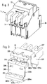
- an electromagnetic drive is shown in a schematic exploded view, as it is used for the operational switching of currents in the load area and with a quick release connected in series to protect against currents in the overload area, for example in connection with a motor protection switch.
- the switching drive according to FIG. 1 is accommodated in a housing, consisting of the lower housing part 10 and the upper housing part 20, the housing parts being produced, for example, as injection molded parts from a suitable thermoplastic insulating plastic.
- the carrier module 30 is equipped with the electrical functional parts, namely in the arrow direction K with the fixed contacts and movable contacts of the switch, in the arrow direction S with the quick release, for example designed as a striking magnet, in the arrow direction SM with the switching magnet made of coil 70, armature 50 and magnet 60, the bridge 40, in which the switching magnet is suspended and the auxiliary switch 80 placed on the bridge 40.
- the carrier module 30 equipped with the aforementioned parts is then inserted into the lower housing part 10 and by fitting the upper housing part 20 and locking the upper housing part with the lower housing part tense and fixed.
- the lower housing part and upper housing part are screwed together.
- an AC drive with coil 70, armature 50 and magnet 60 is shown. It is also possible to use a DC drive for the instead of an AC drive Switch drive to use.
- the electromagnetic switching drive 1 assembled according to FIG. 1 is shown in a perspective view with the lower housing part 10, upper housing part 20 and connection contacts 3 in a possible embodiment in approximately natural size.
- the carrier module 30 inserted into the housing of the switching drive is the centerpiece, which is open on all sides and is easy to assemble and accommodates the electrical functional parts for switching and protecting.
- the individual parts of the switch are designed in such a way that the parts preassembled for the units armature 50, magnet 60, coil 70, auxiliary switch 80 are inserted into the bridge 40 and can be used together with the latter in the carrier module 30.
- a special type of adjustment is dispensed with, since the subsequent locking of the housing parts 10, 20 to one another and screwing fix the coil within the switching drive.
- FIGS 6a and 6b show two perspective views of the carrier module 30 for the switching drive according to Figure 2 in an enlarged view.
- the carrier module 30 is subdivided into three receiving areas which are separated from one another by walls, a central, vertically extending partition 301 separating the receiving area or the receiving chamber for the switching magnet from the two vertically superposed receiving areas for the quick release and the switch.
- a central, vertically extending partition 301 separating the receiving area or the receiving chamber for the switching magnet from the two vertically superposed receiving areas for the quick release and the switch.
- the floor chamber 308 At the bottom of the central partition 301 is the floor chamber 308 with the floor 340, the mutually opposite side walls 310, 311 and a closing front wall.
- Ribs 312 formed on the outside in pairs in the front wall for inserting the Connection contacts formed.
- groove-shaped recesses 336, 337 are provided on the upper side in the central region, into which the magnet 60 of the AC drive engages laterally and is thus fixed in its position in the floor pan 308.
- a plurality of recesses 309 are provided, into which plug-in feet formed on the coil of the switching magnet can be inserted for fixing the position.
- Lateral guide strips 302, 303 with guide grooves 304, 305 are formed on the vertical sides of the partition 301, which are used for receiving by inserting the bridge 40 from above.
- the guide grooves 304, 305 are connected to one another in the base region of the base trough 308 by a further groove 331.
- the switching chambers 313, 314, 315; 323, 324, 325 for the fixed and movable contacts of the switch and for the quick release by means of partitions 317, 318 branching perpendicularly from the partition 301 and the outer walls 316, 319.
- the switching chambers for the switches 313, 314, 315 are located in the upper area and are separated from the receiving chambers 325, 324, 323 for the quick release mechanism by partition walls, which are not described in more detail.
- the movable contacts 5 of the switch are resiliently mounted in contact bridge carriers 90, see FIGS. 10a, 10b, 10c.
- opposite guide webs 320 are formed in the walls delimiting the switching chambers 313, 314, 315 with guide grooves 321, 322 adjoining on both sides along which the contact bridge carriers are slidably guided.
- two latching cams 326, 327 are integrally formed on the carrier module 30 in the region of the outside of the switching chambers and receiving chambers for the switch and the quick release, which snap into corresponding recesses in the lower housing part and thus position the position of the carrier module 30 in the lower housing part.
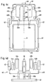
- FIGS. 4a-d show the bridge 40 for receiving an AC drive for the switching drive according to FIG. 2 on an enlarged scale.
- FIG. 4a shows the side view of bridge 40 with attached anchor 50
- FIG. 4b the front view of the bridge according to FIG. 4a with attached anchor
- FIG. 4c the rear view without anchor
- FIG. 4d the top view without anchor.
- the bridge 40 has a window-like, approximately rectangular guide frame 41, with which it can be inserted into the guide grooves 304, 305 of the carrier module 30.
- the bridge has the further frame-like part 49, referred to as the switching frame, which, parallel to the guide frame, is connected to the guide frame via transverse webs 49e, 49d in the region of the upper crossbar 410 of the guide frame, as seen from the side view and top view according to FIG 4a and 4d can be seen.
- the guide frame 41 serves to hold the switching magnet and the guide in the carrier module, while the switching frame 49 serves to engage the contact plunger of the movable contacts of the switch and auxiliary switch for switching.
- the bridge 40 is along its vertical Center axis X is formed symmetrically.
- protruding cams 411 are formed on the side opposite the switching frame 49 for fitting the coil 70.
- horizontal projections are also formed on the side facing away from the switching frame 49, which are used to fasten the armature 50 of the switching magnet.
- lateral holding plates 42, 43 are provided, which are formed on their inside with mutually directed projections 422, 432 and grooves 421, 431, into which the armature with grooves 51, 52 formed on its outer sides can be inserted with a snug fit.
- Projections 44a, b, 45a, b and the central projection 46 extend horizontally from the transverse spar, see also FIGS.
- a central central web 47 extends vertically from the guide frame 41 from the upper cross bar 410, which merges approximately in the area of the upper cross bar 49 c of the switching frame into a cross bar 48 which freely cantilevered with a front latching lug 481 in the area of the guide frame and the projections for the armature and is connected to the switching frame 49 on the other side via a shoulder 482.
- the switching frame 49 has two vertical side webs 49a, 49b, which are connected to the guide frame 41 via the connecting webs 49e, d. Furthermore, a central, freely projecting web 49f is formed, starting from the upper cross member 49c of the switching frame, see FIG. 4c.
- recesses 494 and 495 in the side webs 49a, 49b of the switching frame for taking the contact plunger of the opener or closer, i.e. the movable contacts of the auxiliary switch.
- the bridge 40 shown in FIGS. 4a-d is particularly suitable for accommodating an AC drive with coil 70, armature 50 and magnet 60, see FIG. 14a.
- the bridge 40 according to FIG. 4a is also shown in a side view with the armature 50 suspended for AC drive and with the coil 70 additionally suspended.
- the coil 70 is loosely inserted into the armature 50.
- the holding body 72 of the coil has an upper holding plate 721 and a lower holding plate 720 which protrude beyond the winding. After hanging in the armature 50, the coil 70 rests with its lower holding plate 720 on the lower cross member of the guide frame 41 and on the latching projections 411.
- protruding plug feet 724a, b, c are formed, which are inserted into corresponding recesses 309 in the base trough 308 of the carrier module 30, see FIG. 6a.
- protruding projections on the holding plate 72 can be formed on the holding body 72 for seating and support on the floor 340 of the floor pan 308.
- projections 722 are formed on the upper holding plate 721 of the coil body, which engage in the guide frame 41 of the bridge 40 and limit the movement of the coil upward by abutment on the inside of the upper crossbar of the guide frame.
- FIG. 9 shows the view A on the coil 70 without the bridge 40.
- the receiving areas 723a and 723b for the coil connections are marked.
- FIG. 14a shows the coil 70 with winding and coil connections in a perspective, reduced representation.
- FIGS. 8 and 9 also show the coil and the bridge on an enlarged scale.
- FIG. 10a, 10b, 10c shows the contact bridge carrier 90 for the movable contacts 5 of the switch, which are inserted into the switching chambers 313, 314, 315 of the carrier module, see FIGS. 6a, 6b.
- FIG. 10a shows the cross section according to FIG. 10b
- FIG. 10b shows a side view
- FIG. 10c shows the top view of FIG. 10a.
- the contact bridge carrier 90 made of plastic has on its upper side the molded contact plunger 92 projecting centrally towards one side.
- a receiving chamber 94 is formed in the contact bridge carrier 90, which is formed on two opposite sides with a window 98, 99 for pushing through the contact bridge 91 carrying the contacts 5.
- the window-like recesses 98, 99 are accessible via a slot 95 from the underside of the contact bridge carrier 90, via this slot 95 the contact bridge 91 can be inserted into the contact bridge carrier 90 into the chamber and through the recesses 98, 99.
- the contact bridge 91 is resiliently fixed against the edge of the recesses 98, 99 by means of a compression spring 93 which is arranged in the chamber 94.
- FIG. 7 shows the auxiliary switch 80 in three views, namely front view, top view and cross section on an enlarged scale, but in the view of FIGS. 7a, 7b without the contact bridge carrier 85 carrying the movable contact.
- the housing of the auxiliary switch 80 is parallel to the side walls 801 , 802, dividing walls 806, 805 divided into two switching chamber areas 810, 820, wherein dividing walls 803, 804 are additionally formed in each of these switching chambers between the connections 86a, 86b, 86c, 86d.
- a free space 830 with an intermediate web 831 connecting the two partition walls 805, 806 is formed between the partition walls 805 and 806.
- the two break contacts 81 are accommodated as fixed contacts in the switching chamber 810 and the two fixed contacts 82 as make contacts in the switching chamber 820.
- the contact bridge carrier 85 as shown in FIG. 7c, is used as an opener and is in the rest position in the closed position. If the contact bridge carrier 85 is inserted rotated by 180 °, it is to be used as a make contact in connection with the fixed contact 82.
- the side walls 801, 802 of the housing of the auxiliary switch 80 are closed at the rear in the area of the contacts with wall parts 807, 808, these wall parts being connected to one another via a bridge 809 across the partitions 806, 805.
- the plunger 851 of the contact bridge carrier 85 which carries the movable contact 853, is displaceably mounted in this slot.
- the contact plunger 851 protruding here is hooked into the corresponding recess 495 or 494 of the bridge 40, see FIGS. 4a-c.
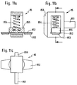
- the contact bridge carrier 85 according to FIG. 7c is shown in more detail and in an enlarged representation in FIGS. 11a, 11b, 11c.
- 11a shows the cross section according to FIG. 11b
- FIG. 11c shows the top view of FIG. 11a.
- the contact bridge carrier 85 which carries the movable contacts 853 of the auxiliary switch on the contact bridge 852, has a frame-like housing, into which the contact bridge 852 is inserted and held by means of the compression spring 854 with a counter bearing 855.
- a projecting web 856 is integrally formed in one plane perpendicular to the extension of the contact bridge 852 on one side of the contact plunger 851 and on the opposite side.
- the above web 856 serves as a guide web for the contact bridge support, which projects into the groove 836 and 837 of the auxiliary switch 80, see FIGS. 7b and 7c, and is displaceable along this.
- the groove 836 and 837 is arranged opposite the slots 833 and 834 in the rear wall.
- the auxiliary switch 80 according to Figure 7a, b, c is placed on the bridge 40 equipped with the coil 70 and the armature 50 according to Figure 8, in such a way that the connecting web 809 of the rear wall on the saddle or paragraph 482 of the Bridge 40, see Figure 4a, is seated.
- the crossbar 48 of the bridge then protrudes into the free space 830, 831 of the auxiliary switch 80, so that a compression spring can be used in the area between 831 and locking lug 481 of the crossbar 48, which stabilizes the auxiliary switch in this position.
- the lower housing part 10 of the switching drive according to FIG. 2 is in an embodiment shown in perspective in Figures 5a and 5b on an enlarged scale.
- the lower housing part has a bottom which is surrounded by side walls 102, 101, the rear wall 103 and the front wall 104.
- the side walls are provided with bevels 117, 118 in the direction of the rear wall 103.
- Recesses 105 and 111 are provided in pairs in the rear wall near the upper edge, into which latching lugs 326, 325 of the carrier module or latching webs 202a, 202b of the upper housing part 20, see FIG. 3, snap into place.
- partitions 106, 107 are formed in continuation of the switching chambers for the trigger.
- receptacles 108, 109, 110 are formed on the upper side for the connection contacts, and through-bores 112, 113 between the contacts for inserting guide pins 203a, 203b of the upper housing part 20 according to FIG. 3.
- the side walls 101, 102 which are offset in the region of the front wall 104 here have angled guide strips 115, 114 which serve as an abutment for the front wall 208 of the upper housing part 20 according to FIG. 3.
- the upper housing part 20 for the switching drive according to FIG. 2 is shown in perspective on an enlarged scale.
- the upper housing part is also injection molded from a thermoplastic, like the lower housing part.
- the upper housing part has a configuration which is adapted to the structure of the assembled and inserted carrier module and which is equipped with respective openings for the different connections.
- Continuous recesses 207 are provided in the area of the connecting lugs 3 in the rear part of the upper housing part 20.
- the through holes 206 for the auxiliary switch connections are formed in the head region of the upper housing part 20, the openings 204 for the coil connections in the subsequently offset head region and the openings 205 for the mains connections in the foremost head region.
- the head area with the recesses 204 and the front area with The front wall 208 connecting the recesses 205 is laterally provided with a chamfer 208b with which it engages behind the strips 114, 115 of the lower housing part.
- the protruding web 208a is formed in an extension of the front wall 208 below the cover area carrying the recesses 205.
- the rear area of the upper housing part 20 is lined with side walls 201, 202, these being connected to one another by a rear wall in the area behind the recesses 207.
- a chamfered bevel 201a is also formed on the side walls 201, analogously to the bevel 117, 118 of the side walls of the lower housing part 10, in the region of which the side wall is seated on the side walls of the lower housing part.
- the recesses 204 in the upper part 20 of the housing are also assigned to the recesses 204 in the front wall 208 in the coil connection area.
- FIG. 13 the assembly of the carrier module 30 with the connection contacts and quick-release devices is shown in an exploded view.
- the carrier module as described above in FIGS. 6a, b is equipped with the trigger in the form of impact magnets from the underside, which are inserted into the corresponding chambers 323, 324, 325.
- the connection contacts 7c, 7b are attached from below and the connection contacts 7d, 7a carrying the fixed contacts 4 are inserted from above (or below) into the switching chambers 313, 314, 315.
- the connection contacts 7a and 7b are brazed or welded together.
- the carrier module equipped with the electrical connection parts according to FIG. 13 is then further equipped according to FIG. 14a.
- the individual firing pins 6a are then inserted into the trigger, from above.
- the bridge 40 equipped with auxiliary switch 80 and armature 50 is completed by hanging the coil 70 and inserting the magnet 60 into the coil from below, and then the bridge is inserted into the guide grooves of the carrier module.
- the lower part of the switching frame 49 of the bridge 40 snaps, see FIGS. 4a-d into the slots 306, 306a, 307, 307a of the carrier module according to FIGS. 6a, b.
- the contact bridge carriers 85 are inserted into the auxiliary switch 80.
- the module 30 fully equipped in this way is then inserted into the lower housing part 10, wherein it engages with the locking cams in the rear wall of the housing.
- the parts assembled according to FIG. 14a form the switching drive according to FIG. 14b without a housing cover.
- the housing upper part 10 according to FIG. 3 is then placed on the mounting block according to FIG. 14b and clamped in the rear wall of the housing lower part by latching with the latching hooks.
- the pins of the upper housing part snap into the corresponding recesses of the lower housing part and then a screw is inserted from below into the threaded pins of the upper housing part and the upper housing part is clamped against the lower housing part by screwing.
- the coil is also fixed in the housing.
- the construction of the bridge 40 has to be adapted to the design of the DC drive, for which an example in FIG. 15 is shown in an exploded view.
- the coil 70 which is equipped with a winding, permanent magnet and a central rod armature, is formed in the coil holder with connections as a compact component, see FIG. 15.
- the bridge for mounting the coil is 70 in the area of the lower cross member with a wider projection 401. The projections required for the attachment of the armature of the AC drive on the upper cross member of the bridge 40, see FIGS.
- FIG. 8 A variant of the coil anchoring or the anchoring of the coil holder 72 of the coil 70 in the carrier module 30 is shown in part in FIG. Instead of the plug-in feet 724a, b, c of the coil according to FIG. 8 for AC drive, the feet of the coil holder 72 are hook-shaped curved inwards, see the hook-shaped feet 724e, 724d. These hook-shaped feet of the coil former 72 then reach through the recesses 309 of the base 340 of the base trough of the carrier module and snap behind projections 341, 342 in the bottom wall in the region of the openings or recesses 309, which are designed as latching cams.
- the coil 70 inserted into the carrier module 30 together with the magnetic body 60 is then inserted into the lower housing part 10 during final assembly, as shown in FIG. 14a.
- the final fixing and fixing of the coil 70 with respect to the carrier 30 then takes place when the hook-shaped feet 724e, 724d rest on corresponding projections 141, 140 formed on the bottom of the lower housing part 10 between the two housing parts, as described above, the coil 70 is then clamped and fixed in the housing.
- the configuration of the coil holder in the carrier module and in the housing of the switching drive, shown in part in FIG. 12, has, for example, four hook-shaped feet on the underside of the coil body, which are each formed in pairs on opposite sides of the coil body. It is also possible to arrange two hook-shaped feet on one side and a hook-shaped foot centrally on the other side. Since the coil former is injection molded from a suitable thermoplastic, the hook-shaped feet are sufficiently resiliently flexible so that they can snap behind the projections 341, 342 when inserted into the carrier module.
Landscapes
- Physics & Mathematics (AREA)
- Electromagnetism (AREA)
- Push-Button Switches (AREA)
- Emergency Protection Circuit Devices (AREA)
- Breakers (AREA)
- Switch Cases, Indication, And Locking (AREA)
Applications Claiming Priority (2)
| Application Number | Priority Date | Filing Date | Title |
|---|---|---|---|
| DE4244606 | 1992-12-31 | ||
| DE4244606A DE4244606C2 (de) | 1992-12-31 | 1992-12-31 | Elektromagnetisches Schaltgerät |
Publications (2)
| Publication Number | Publication Date |
|---|---|
| EP0604985A1 true EP0604985A1 (fr) | 1994-07-06 |
| EP0604985B1 EP0604985B1 (fr) | 1997-08-13 |
Family
ID=6476868
Family Applications (1)
| Application Number | Title | Priority Date | Filing Date |
|---|---|---|---|
| EP93121025A Expired - Lifetime EP0604985B1 (fr) | 1992-12-31 | 1993-12-28 | Commande électromagnétique de commutateur |
Country Status (4)
| Country | Link |
|---|---|
| EP (1) | EP0604985B1 (fr) |
| AT (1) | ATE156933T1 (fr) |
| DE (1) | DE4244606C2 (fr) |
| ES (1) | ES2106950T3 (fr) |
Cited By (4)
| Publication number | Priority date | Publication date | Assignee | Title |
|---|---|---|---|---|
| WO2005038840A1 (fr) * | 2003-10-16 | 2005-04-28 | Moeller Gmbh | Systeme pour fixer des barres conductrices pour des appareils de commutation multiphases |
| CN111029217A (zh) * | 2019-12-30 | 2020-04-17 | 三友联众集团股份有限公司 | 一种绝缘体分体式电磁继电器 |
| EP3561848A4 (fr) * | 2016-12-20 | 2020-07-29 | Zhejiang Chint Electrics Co., Ltd. | Contacteur |
| CN116598170A (zh) * | 2023-06-12 | 2023-08-15 | 深圳市揽盛电气技术有限公司 | 基于壳体优化的交流接触器构造 |
Families Citing this family (8)
| Publication number | Priority date | Publication date | Assignee | Title |
|---|---|---|---|---|
| DE19653378A1 (de) * | 1996-12-20 | 1998-06-25 | Abb Patent Gmbh | Installationsschalter |
| DE19814432C1 (de) * | 1998-03-31 | 1999-12-23 | Moeller Gmbh | Elektromagnetisches Schaltgerät mit einem mehrteiligen Gehäuse |
| DE10013103C1 (de) * | 2000-03-17 | 2001-11-29 | Aeg Niederspannungstech Gmbh | Gehäuse |
| DE10216371A1 (de) * | 2002-04-12 | 2003-10-23 | Abb Patent Gmbh | Hilfsschalter |
| DE102007048424B3 (de) * | 2007-10-09 | 2009-06-18 | Siemens Ag | Kontaktträgereinheiten eines Schaltgerätes sowie Schaltgerät |
| CN101826423B (zh) * | 2010-04-16 | 2012-08-29 | 江苏辉能电气有限公司 | 一种低压断路器的模块化电子脱扣器 |
| DE202018102942U1 (de) * | 2018-05-25 | 2018-08-01 | Oliver Mangelberger | Haube für ein Schaltelement und zugehörige Schalteranordnung |
| CN121768913A (zh) * | 2024-09-29 | 2026-03-31 | 泰科电子科技(苏州工业园区)有限公司 | 接触器动触头组件和接触器 |
Citations (5)
| Publication number | Priority date | Publication date | Assignee | Title |
|---|---|---|---|---|
| FR2335030A1 (fr) * | 1975-12-08 | 1977-07-08 | Elesta Ag Elektronik | Relais electromagnetique et son procede de fabrication |
| FR2579015A1 (fr) * | 1985-03-18 | 1986-09-19 | Telemecanique Electrique | Interrupteur multipolaire a commande electromagnetique |
| EP0287752A2 (fr) * | 1987-04-22 | 1988-10-26 | Moeller GmbH | Interrupteur électromagnétique avec entraînement électromagnétique |
| EP0325071A1 (fr) * | 1988-01-20 | 1989-07-26 | Hager Electro S.A. | Appareil de protection d'installations électriques |
| EP0405688A1 (fr) * | 1989-06-28 | 1991-01-02 | Holec Systemen En Componenten B.V. | Châssis de support pour interrupteur |
-
1992
- 1992-12-31 DE DE4244606A patent/DE4244606C2/de not_active Expired - Fee Related
-
1993
- 1993-12-28 EP EP93121025A patent/EP0604985B1/fr not_active Expired - Lifetime
- 1993-12-28 AT AT93121025T patent/ATE156933T1/de not_active IP Right Cessation
- 1993-12-28 ES ES93121025T patent/ES2106950T3/es not_active Expired - Lifetime
Patent Citations (6)
| Publication number | Priority date | Publication date | Assignee | Title |
|---|---|---|---|---|
| FR2335030A1 (fr) * | 1975-12-08 | 1977-07-08 | Elesta Ag Elektronik | Relais electromagnetique et son procede de fabrication |
| FR2579015A1 (fr) * | 1985-03-18 | 1986-09-19 | Telemecanique Electrique | Interrupteur multipolaire a commande electromagnetique |
| EP0287752A2 (fr) * | 1987-04-22 | 1988-10-26 | Moeller GmbH | Interrupteur électromagnétique avec entraînement électromagnétique |
| DE3713412A1 (de) * | 1987-04-22 | 1988-11-03 | Kloeckner Moeller Elektrizit | Elektromagnetisches schaltgeraet mit elektromagnetischem antrieb |
| EP0325071A1 (fr) * | 1988-01-20 | 1989-07-26 | Hager Electro S.A. | Appareil de protection d'installations électriques |
| EP0405688A1 (fr) * | 1989-06-28 | 1991-01-02 | Holec Systemen En Componenten B.V. | Châssis de support pour interrupteur |
Cited By (6)
| Publication number | Priority date | Publication date | Assignee | Title |
|---|---|---|---|---|
| WO2005038840A1 (fr) * | 2003-10-16 | 2005-04-28 | Moeller Gmbh | Systeme pour fixer des barres conductrices pour des appareils de commutation multiphases |
| US7307500B2 (en) | 2003-10-16 | 2007-12-11 | Moeller Gmbh | Arrangement used to fix conductor rails for multi-phase switchgears |
| CN100511525C (zh) * | 2003-10-16 | 2009-07-08 | 默勒有限公司 | 用于多相开关装置的接触轨固定的装置 |
| EP3561848A4 (fr) * | 2016-12-20 | 2020-07-29 | Zhejiang Chint Electrics Co., Ltd. | Contacteur |
| CN111029217A (zh) * | 2019-12-30 | 2020-04-17 | 三友联众集团股份有限公司 | 一种绝缘体分体式电磁继电器 |
| CN116598170A (zh) * | 2023-06-12 | 2023-08-15 | 深圳市揽盛电气技术有限公司 | 基于壳体优化的交流接触器构造 |
Also Published As
| Publication number | Publication date |
|---|---|
| ES2106950T3 (es) | 1997-11-16 |
| DE4244606A1 (de) | 1994-07-07 |
| DE4244606C2 (de) | 1995-08-31 |
| ATE156933T1 (de) | 1997-08-15 |
| EP0604985B1 (fr) | 1997-08-13 |
Similar Documents
| Publication | Publication Date | Title |
|---|---|---|
| EP0036027B1 (fr) | Contacteur éléctromagnétique | |
| DE4438801C1 (de) | Modulare Steuerungsanlage | |
| EP0185107B1 (fr) | Disjoncteur de protection pour moteurs | |
| EP0604985B1 (fr) | Commande électromagnétique de commutateur | |
| EP0237607A1 (fr) | Contacteur | |
| DE19818058C2 (de) | Schaltgerät mit einer Schaltkammer-Baugruppe | |
| DE2039840A1 (de) | Elektromagnetisches Schuetz | |
| DE3817002A1 (de) | Elektromagnetisches schaltgeraet | |
| EP0017124A1 (fr) | Appareil électrique, notamment appareil d'installation | |
| EP0000711B1 (fr) | Contacteur avec bornes de raccordement librement accessibles et disposées dans des plans différents | |
| DE4207156C2 (de) | Konstruktion eines elektrischen Schalters und eines Sicherungshalters | |
| DE3042029A1 (de) | Abdeckvorrichtung zur sicherung von anschlussklemmen von elektrischen installationsgeraeten | |
| EP0036432B2 (fr) | Contacteur, en particulier un contacteur de puissance ou de commande ou de mise en marche | |
| DE9403259U1 (de) | Gehäuseaufbau für einen Niederspannungs-Schutzschalter mit Hilfsschalterblock | |
| DE1614837C3 (de) | Elektromagnetisches Schütz | |
| DE3316202C2 (de) | Fernsprechapparat | |
| DE3409564A1 (de) | Lichtbogenloescheinrichtung | |
| DE69215348T2 (de) | Schaltgeräte für elektromagnetische und manuelle Betätigung | |
| DE3228469A1 (de) | Vorrichtung zur stellungsanzeige an schaltgeraeten | |
| DE2416152A1 (de) | Leistungsschalter | |
| DE19846219B4 (de) | Stromschalter | |
| EP0075661A2 (fr) | Dispositif pour la fixation rapide d'appareils électriques sur rails de support normalisés | |
| DE10002125A1 (de) | Schnellbefestigung für ein elektrisches Installationsgerät | |
| DE2038879C3 (de) | Relais, insbesondere in Flachbauform | |
| DE69022492T2 (de) | Halterrahmen für einen Schalter. |
Legal Events
| Date | Code | Title | Description |
|---|---|---|---|
| PUAI | Public reference made under article 153(3) epc to a published international application that has entered the european phase |
Free format text: ORIGINAL CODE: 0009012 |
|
| AK | Designated contracting states |
Kind code of ref document: A1 Designated state(s): AT CH ES FR GB IT LI SE |
|
| 17P | Request for examination filed |
Effective date: 19941207 |
|
| 17Q | First examination report despatched |
Effective date: 19951218 |
|
| GRAG | Despatch of communication of intention to grant |
Free format text: ORIGINAL CODE: EPIDOS AGRA |
|
| GRAH | Despatch of communication of intention to grant a patent |
Free format text: ORIGINAL CODE: EPIDOS IGRA |
|
| GRAH | Despatch of communication of intention to grant a patent |
Free format text: ORIGINAL CODE: EPIDOS IGRA |
|
| GRAH | Despatch of communication of intention to grant a patent |
Free format text: ORIGINAL CODE: EPIDOS IGRA |
|
| GRAA | (expected) grant |
Free format text: ORIGINAL CODE: 0009210 |
|
| AK | Designated contracting states |
Kind code of ref document: B1 Designated state(s): AT CH ES FR GB IT LI SE |
|
| REF | Corresponds to: |
Ref document number: 156933 Country of ref document: AT Date of ref document: 19970815 Kind code of ref document: T |
|
| REG | Reference to a national code |
Ref country code: CH Ref legal event code: EP |
|
| ITF | It: translation for a ep patent filed | ||
| REG | Reference to a national code |
Ref country code: CH Ref legal event code: NV Representative=s name: E. BLUM & CO. PATENTANWAELTE |
|
| GBT | Gb: translation of ep patent filed (gb section 77(6)(a)/1977) |
Effective date: 19971017 |
|
| ET | Fr: translation filed | ||
| REG | Reference to a national code |
Ref country code: ES Ref legal event code: FG2A Ref document number: 2106950 Country of ref document: ES Kind code of ref document: T3 |
|
| PLBE | No opposition filed within time limit |
Free format text: ORIGINAL CODE: 0009261 |
|
| STAA | Information on the status of an ep patent application or granted ep patent |
Free format text: STATUS: NO OPPOSITION FILED WITHIN TIME LIMIT |
|
| 26N | No opposition filed | ||
| PGFP | Annual fee paid to national office [announced via postgrant information from national office to epo] |
Ref country code: GB Payment date: 20001211 Year of fee payment: 8 |
|
| PGFP | Annual fee paid to national office [announced via postgrant information from national office to epo] |
Ref country code: SE Payment date: 20001221 Year of fee payment: 8 |
|
| PGFP | Annual fee paid to national office [announced via postgrant information from national office to epo] |
Ref country code: AT Payment date: 20011203 Year of fee payment: 9 |
|
| PG25 | Lapsed in a contracting state [announced via postgrant information from national office to epo] |
Ref country code: GB Free format text: LAPSE BECAUSE OF NON-PAYMENT OF DUE FEES Effective date: 20011228 |
|
| PG25 | Lapsed in a contracting state [announced via postgrant information from national office to epo] |
Ref country code: SE Free format text: LAPSE BECAUSE OF NON-PAYMENT OF DUE FEES Effective date: 20011229 |
|
| REG | Reference to a national code |
Ref country code: GB Ref legal event code: IF02 |
|
| EUG | Se: european patent has lapsed |
Ref document number: 93121025.6 |
|
| GBPC | Gb: european patent ceased through non-payment of renewal fee |
Effective date: 20011228 |
|
| PGFP | Annual fee paid to national office [announced via postgrant information from national office to epo] |
Ref country code: CH Payment date: 20021125 Year of fee payment: 10 |
|
| PGFP | Annual fee paid to national office [announced via postgrant information from national office to epo] |
Ref country code: ES Payment date: 20021127 Year of fee payment: 10 |
|
| PG25 | Lapsed in a contracting state [announced via postgrant information from national office to epo] |
Ref country code: AT Free format text: LAPSE BECAUSE OF NON-PAYMENT OF DUE FEES Effective date: 20021228 |
|
| PG25 | Lapsed in a contracting state [announced via postgrant information from national office to epo] |
Ref country code: ES Free format text: LAPSE BECAUSE OF NON-PAYMENT OF DUE FEES Effective date: 20031229 |
|
| PG25 | Lapsed in a contracting state [announced via postgrant information from national office to epo] |
Ref country code: LI Free format text: LAPSE BECAUSE OF NON-PAYMENT OF DUE FEES Effective date: 20031231 Ref country code: CH Free format text: LAPSE BECAUSE OF NON-PAYMENT OF DUE FEES Effective date: 20031231 |
|
| REG | Reference to a national code |
Ref country code: CH Ref legal event code: PL |
|
| REG | Reference to a national code |
Ref country code: ES Ref legal event code: FD2A Effective date: 20031229 |
|
| PG25 | Lapsed in a contracting state [announced via postgrant information from national office to epo] |
Ref country code: IT Free format text: LAPSE BECAUSE OF NON-PAYMENT OF DUE FEES;WARNING: LAPSES OF ITALIAN PATENTS WITH EFFECTIVE DATE BEFORE 2007 MAY HAVE OCCURRED AT ANY TIME BEFORE 2007. THE CORRECT EFFECTIVE DATE MAY BE DIFFERENT FROM THE ONE RECORDED. Effective date: 20051228 |
|
| PGFP | Annual fee paid to national office [announced via postgrant information from national office to epo] |
Ref country code: FR Payment date: 20081212 Year of fee payment: 16 |
|
| REG | Reference to a national code |
Ref country code: FR Ref legal event code: ST Effective date: 20100831 |
|
| PG25 | Lapsed in a contracting state [announced via postgrant information from national office to epo] |
Ref country code: FR Free format text: LAPSE BECAUSE OF NON-PAYMENT OF DUE FEES Effective date: 20091231 |