EP0605004B1 - Dispositif de courbage d'aiguilles avec alimentation automatique - Google Patents
Dispositif de courbage d'aiguilles avec alimentation automatique Download PDFInfo
- Publication number
- EP0605004B1 EP0605004B1 EP93121083A EP93121083A EP0605004B1 EP 0605004 B1 EP0605004 B1 EP 0605004B1 EP 93121083 A EP93121083 A EP 93121083A EP 93121083 A EP93121083 A EP 93121083A EP 0605004 B1 EP0605004 B1 EP 0605004B1
- Authority
- EP
- European Patent Office
- Prior art keywords
- needle
- curving
- mandrel
- blank
- roller
- Prior art date
- Legal status (The legal status is an assumption and is not a legal conclusion. Google has not performed a legal analysis and makes no representation as to the accuracy of the status listed.)
- Expired - Lifetime
Links
- 238000000034 method Methods 0.000 claims description 12
- 238000011084 recovery Methods 0.000 claims description 9
- 238000003825 pressing Methods 0.000 claims description 5
- 230000001419 dependent effect Effects 0.000 claims description 3
- 230000003213 activating effect Effects 0.000 claims description 2
- 239000000463 material Substances 0.000 description 10
- 230000003287 optical effect Effects 0.000 description 7
- 238000007493 shaping process Methods 0.000 description 6
- 238000005452 bending Methods 0.000 description 5
- 238000000151 deposition Methods 0.000 description 4
- 238000004519 manufacturing process Methods 0.000 description 4
- 239000013536 elastomeric material Substances 0.000 description 3
- 229920002635 polyurethane Polymers 0.000 description 3
- 239000004814 polyurethane Substances 0.000 description 3
- 229920000271 Kevlar® Polymers 0.000 description 2
- 239000004677 Nylon Substances 0.000 description 2
- 230000004913 activation Effects 0.000 description 2
- 239000011248 coating agent Substances 0.000 description 2
- 238000000576 coating method Methods 0.000 description 2
- 239000004761 kevlar Substances 0.000 description 2
- 229920001778 nylon Polymers 0.000 description 2
- 229920001084 poly(chloroprene) Polymers 0.000 description 2
- 238000001356 surgical procedure Methods 0.000 description 2
- 241001465754 Metazoa Species 0.000 description 1
- 229910000831 Steel Inorganic materials 0.000 description 1
- 238000005520 cutting process Methods 0.000 description 1
- 229920001971 elastomer Polymers 0.000 description 1
- 239000000806 elastomer Substances 0.000 description 1
- XPYGGHVSFMUHLH-UUSULHAXSA-N falecalcitriol Chemical compound C1(/[C@@H]2CC[C@@H]([C@]2(CCC1)C)[C@@H](CCCC(O)(C(F)(F)F)C(F)(F)F)C)=C\C=C1\C[C@@H](O)C[C@H](O)C1=C XPYGGHVSFMUHLH-UUSULHAXSA-N 0.000 description 1
- 238000000227 grinding Methods 0.000 description 1
- 235000012054 meals Nutrition 0.000 description 1
- 238000002360 preparation method Methods 0.000 description 1
- 239000011241 protective layer Substances 0.000 description 1
- 239000012858 resilient material Substances 0.000 description 1
- 239000007787 solid Substances 0.000 description 1
- 239000010959 steel Substances 0.000 description 1
- 210000003813 thumb Anatomy 0.000 description 1
Images


Classifications
-
- B—PERFORMING OPERATIONS; TRANSPORTING
- B21—MECHANICAL METAL-WORKING WITHOUT ESSENTIALLY REMOVING MATERIAL; PUNCHING METAL
- B21F—WORKING OR PROCESSING OF METAL WIRE
- B21F1/00—Bending wire other than coiling; Straightening wire
-
- B—PERFORMING OPERATIONS; TRANSPORTING
- B21—MECHANICAL METAL-WORKING WITHOUT ESSENTIALLY REMOVING MATERIAL; PUNCHING METAL
- B21G—MAKING NEEDLES, PINS OR NAILS OF METAL
- B21G1/00—Making needles used for performing operations
Definitions
- the present invention relates to needle curving devices. More particularly, the invention relates to a rotating needle curving device for sequentially curving a multiplicity of needles.
- the production of needles involves many processes and different types of machinery in order to prepare quality needles from raw stock. These varying processes and machinery become more specialized in the preparation of surgical needles where the environment of intended use is in humans or animals.
- Some of the processes involved in the production of surgical grade needles include, inter alia: straightening spooled wire stock, cutting needle blanks from raw stock, tapering or grinding points on one end of the blank, providing a bore for receiving suture thread at the other end of the blank, flat pressing a portion of the needle barrel to facilitate easier grasping by surgical instrumentation, and curving the needle where curved needles are desired.
- Conventional needle processing is, in large part, a labor intensive operation requiring highly skilled workmen. Generally, extreme care must be taken to ensure that only the intended working of the needle is performed and the other parts of the needle remain undisturbed.
- Curved needles have advantages over other needle configurations in many surgical procedures for a variety of reasons including, uniformity of entry depth for multiple sutures and proper "bite" of tissue surrounding the incision or wound.
- a specified curvature i.e., a predetermined radius of curvature.
- the predetermined radius of curvature for the needle varies with specific applications and the size of the needle.
- Conventional needle curving techniques create the curve by manually forming the machined needle around an anvil structure having a desired curvature.
- the anvil structure provides a shaping surface for forming the needle.
- the needle in positioned for curving by manually holding the needle in engagement with the anvil structure with a holding device. The needle is subsequently bent by manually manipulating the holding device so the needle curvature is formed about the shaping surface of the anvil structure.
- the anvil or mandrel used may have a smaller radius than the radius desired in the final needle. This configuration allows for some springback after the bending operation and ensures that the desired radius of curvature is attained. A disclosure of such features may be found in, for example, U.S. Patent No. 4,524,771 to McGregor et al.
- the present invention provides an apparatus for forming curved surgical needles according to claim 1 which comprises curving means for imparting an arcuate profile to at least a portion of a needle blank and rotating means for pressing the needle blank about the curving means.
- the apparatus also provides needle advancing means for receiving the needle blank in a needle presenting station and for advancing the needle blank to a needle curving station while needle supply means sequentially supplies needle blanks to the needle presenting station.
- the curving means comprises a mandrel adapted to selectively engage at least a portion of the needle blank.
- the mandrel is a shaft having at least a portion thereof configured to impart an arcuate profile to the needle blank.
- the shaft has a curvature with a predetermined radius in the range of between about 1,25 mm (0.05 inches) and about 13 mm (0.5 inches).
- the rotating means of the present invention comprises at least one rotatable member and means for rotating the rotatable member about at least a portion of the curving means.
- Needle advancing means are also provided and comprise at least one pair of rollers with belt means positioned therebetween for supporting the needle blank and advancing the needle blank between the at least one pair of rollers to the needle curving position.
- the belt means comprises an elastic belt formed of a material selected from the group consisting of Neoprene, Nylon, Polyurethane or Kevlar and belt drive means for driving the elastic belt.
- Tensioning means may be provided for applying tension to the belt means.
- Appropriate tensioning means include at least one tensioning roller biased toward the belt means.
- the needle supply means of the present invention preferably comprises clamping means for releasably maintaining the needle blanks, means for sequentially advancing the clamping means toward the needle presenting position, sensing means for sensing the needle blank in the needle presenting position and means for selectively ejecting the needle blanks from the clamping means.
- the clamp advancing means may be configured as a power screw operatively connected to clamp drive means.
- the ejecting means comprises a pusher head slidably secured to pusher head drive means and a pusher pin secured to and extending from the pusher head.
- the present invention also provides a method for forming curved surgical needles according to claim 11.
- the method includes the steps of providing means for forming curved needles, positioning the needle blank between curving means and at least one rotatable member and activating rotating means to form the curvature in the needle blank.
- the forming means comprises a mandrel having a curvature with at least one predetermined radius for selectively engaging at least a portion of a needle blank, the least one rotatable member, and the means for rotating said rotatable member about at least a portion of the mandrel.
- the needle curving apparatus of the present invention is utilized to curve or bend a multiplicity of sequentially presented needle blanks.
- needle blank refers to a surgical needle in various stages of fabrication.
- the needle blanks are flat pressed on two sides prior to curving.
- the needle blank is curved along the pressed sides.
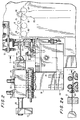
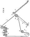
- Fig. 1 illustrates a preferred needle curving apparatus 10 of the present invention.
- the needle curving apparatus 10 includes frame 12, needle supply system 14, needle advancing system 16, needle curving system 18, and needle recovery system 20.
- a control system (not shown) is provided to control the operational sequence of the needle curving apparatus of the present invention.
- An example of a suitable control system includes a GE-Fanuc 9030 Programmable Controller, a LCD display manufactured by Horner Electric and numerous control switches and indicators.
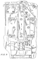
- needle supply system 14 includes needle clamp 22 which is slidably secured to power screw frame 24 and needle pusher assembly 26.
- needle clamp 22 is a two piece member having base 28 which is removably secured to rack 30 and removable top 32 which is secured to base 28 by thumb screws 34.
- the joint between top 32 and base 28 is configured, dimensioned and adapted to receive and releasably maintain a plurality of needle blanks in a row and oriented such that the longitudinal axis of each needle blank is substantially perpendicular to the longitudinal axis of clamp 22, as shown in Fig. 3.
- base 28 is removably secured to rack 30 by locking arm 36, as shown in Fig. 4.
- Locking arm 36 is rotatably secured to rack 30 so that one end portion 36a of locking arm 36 engages channel 38 of base 28 when locking arm 36 is rotated clockwise (best seen in Fig. 4). When locking arm 36 is rotated counter-clockwise, end portion 36a of the locking arm is disengaged from channel 38 of base 28, thus releasing the base from the rack.
- power screw frame 24 is secured to frame 12 by bracket 40 and supports power screw assembly 42 and needle clamp assembly 22.
- Power screw assembly 42 includes drive member 44 and threaded rod member 46 rotatably positioned within power screw frame 24.
- rod member 46 is threaded through base portion 30a of rack 30 which has an internal thread dimensioned to receive threaded rod member 46.
- threaded rod member 46 is operatively connected to drive member 44 by coupler 48 so that rotational movement of drive member 44 is transferred through rod member 46 which translates to linear sliding movement of needle clamp 22.
- Drive member 44 preferably a stepper motor, is operatively connected to the control system and responds to sensors 50, 52 and 54, shown in Fig. 2.
- Optical sensors 52 are secured to each end portion of power screw frame 24, and serve to limit the distance the rack and the needle clamp can move along the power screw frame.
- needle clamp 22 can traverse the longitudinal axis of power screw frame 24 so as to sequentially position the needle blanks in the needle presenting station.
- the needle presenting station is the position of the needle blank in needle clamp 22 which aligns with needle guide 56 of needle advancing system 16, as shown in Fig. 5.
- needle pusher assembly 26 is provided to sequentially eject needle blanks from needle clamp 22 into needle advancing system 16.
- Needle pusher assembly 26 is secured to post 58 and includes a forward portion having pusher head 60 and pusher pin 62 extending from pusher head 60.
- Needle pusher assembly 26 is positioned on bracket 40 so that pusher pin 62 aligns with the needle blank 64 in the needle presenting station. Movement of pusher pin 62 toward needle clamp 22 will push or eject the needle blank from clamp 22 into needle advancing system 16.
- the rear portion 60a of pusher head 60 is connected to piston 66 which extends through pusher drive assembly 68 into engagement with limit arm 70.
- the pusher drive assembly is a pneumatically controlled drive member capable of driving an internal piston between an extended position and a retracted position, which coincides with the above described movement of pusher head 60.
- the pusher drive assembly may be any other known drive system, such as, for example, an electric motor or a hydraulic cylinder.
- Limit switch 72 is secured to post 58 and is operatively connected to the control system so as to disable pusher head 60 when the needle blank has been ejected from needle clamp 22.
- Magnetic sensors 74 and 76 are secured to pusher drive assembly 68 and are operatively connected to the control system. Sensors 74 and 76 are provided to sense whether pusher head 60 is in the extended position (i.e., ejecting a needle blank from the needle clamp) or in the retracted position (i.e., behind the needle blank in the needle presenting position) and are activated when either limit arm 70 or pusher head 60 are in close proximity to corresponding magnetic sensor 74 or 76.
- Optical sensors 50 and 54 are secured to frame 12 and operatively connected to the control system. Optical sensor 50 is provided to determine when the next needle blank is in the needle presenting position and optical sensor 54 is provided to determine when the needle blank has been fully ejected from clamp 22.
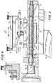
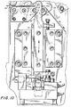
- needle advancing system 16 includes upper guide rollers 78 and lower guide rollers 80 rotatably secured to frame 12. Rollers 78, 80 are spatially positioned to provide a smooth transfer of the needle blank from the needle presenting position to the needle curving station.
- the needle curving station (or needle shaping zone) is the position of the needle blank when it is adjacent to positioning roller 82, curving roller 84 and mandrel 86 for subsequent bending.
- belt drive system 88 includes drive belt 90, drive belt motor 92 and drive shaft 94 which is coupled to motor 92.
- drive belt 90 is a closed loop belt which is routed between upper guide rollers 78 and lower guide rollers 80 and around drive shaft 94 in a tight frictional fit. As a result, rotational movement of drive shaft 94 is transferred to rotational movement of drive belt 90 and lower guide rollers 80.
- drive belt 90 is fabricated from a material which is sufficiently flexible to wrap about lower guide rollers 80 and drive shaft 94 in a friction fit, and of sufficient strength to assist in bending needle blanks about the mandrel without damaging the needle blanks.
- the drive belt may be fabricated from elastomeric material having a durometer value between about 80 and about 90 SHORE D, such as neoprene, nylon, polyurethane, kevlar and the like.
- SHORE D such as neoprene, nylon, polyurethane, kevlar and the like.
- other systems may be utilized to rotate the guide rollers.
- a roller system (not shown) may be provided to transfer rotational movement of the drive shaft to the guide rollers.
- Upper guide rollers 78 are provided to maintain the needle blank in a frictional relationship with drive belt 90 without substantially deforming or marring the needle blank.
- upper and lower guide rollers 78 and 80 are molded and ground into a cylindrical shape from a material having a hardness value substantially equivalent to the hardness value of the needle material.
- Rollers 78 and 80 are then coated with an elastomeric material such as a polyurethane to form a protective layer having sufficient thickness to ensure good frictional contact with drive belt 90 or the needle blank and to help prevent marring of the needle blank.
- the thickness of the coating on rollers 78 and 80 may be in the range of between about 0.4 mm (1/64 inches) and about 3.2 mm (1/8 inch).
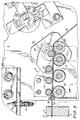
- Belt tensioning system 96 is provided to maintain the tension on belt 90 during the operation of the needle curving apparatus of the present invention.
- belt tensioning system 96 includes idler arm 98, idler rollers 100 and 102 and spring 104.
- One end portion 98a of idler arm 98 is pivotally secured to frame 12 by pin 106.
- Idler roller 100 and spring 104 are secured to the other end portion 98b of idler arm 98.
- Roller 100 which is rotatably secured to the idler arm, and spring 104 are provided to create sufficient downward force on idler arm 98 so as to maintain the proper tension on drive belt 90 during the curving operation, as shown in Figs. 7 and 8.
- Idler roller 102 is rotatably secured to frame 12 in close proximity to drive shaft 94 so as to further increase the tension of drive belt 90.
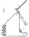
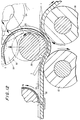
- the needle curving system 18 includes positioning roller 82, curving roller 84 and mandrel assembly 85 to impart an arcuate profile to the needle blank.
- Positioning roller 82 is rotatably secured to frame 12 adjacent to curving roller 84, as shown in Fig. 9.
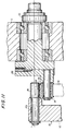
- Curving roller 84 is secured to rotating bracket 108 which passes through frame 12 and engages bracket drive 110, as shown in Fig. 11.
- curving roller 84 can rotate about mandrel 86 to bend the needle blank upon actuation, as shown in Fig. 8.
- rollers 82 and 84 are molded and ground and coated with an elastomeric material similar to lower and upper guide rollers described above. The thickness of the coating on rollers 82 and 84 may be in the range of between about 0.4 mm (1/64 inches) and about 3.2 mm (1/8 inches).
- mandrel assembly 85 includes mandrel 86, mandrel arm 112 and mandrel drive member 114.
- Mandrel drive member 114 is secured to frame 12 and includes piston 116 which is secured to mandrel arm 112.
- Mandrel drive member 114 is provided to reciprocate mandrel drive arm 112 between an open position and a deforming position.
- piston 116 is extended such that mandrel 86 is displaced from rollers 82 and 84 a sufficient distance to allow the needle blank to enter the needle curving station.
- the deforming position shown in Fig.
- mandrel drive member 114 is a pneumatic cylinder, however, the drive member may be any other known drive system, such as an electric motor or a hydraulic cylinder.
- mandrel 86 is positioned adjacent to positioning roller 82 and curving roller 84 in a triangular orientation so that the center axis of mandrel 86 aligns with the center axis of bracket drive member 110, as identified by line "L" in Fig. 11. In this configuration rotational movement of curving roller 84 is centered around mandrel 86 to ensure even curvature of the needle blank.
- Mandrel 86 is a shaft or rod transversely secured to one end portion 112a of mandrel arm 112.
- mandrel 86 has a solid cross-section and is fabricated from a material having a hardness which is at least substantially equal to the hardness of the needle material.
- mandrel 86 has a Rockwell hardness value between 55C and about 57C which discourages unwanted shaping or marring of the needle blank and/or the mandrel.
- mandrel 86 may be coated with an elastomer material to help prevent unwanted marring of the needle blank and/or mandrel 86 during the curving process.
- the mandrel has a circular cross-section to impart an arcuate profile to the needle blank resulting in a curved surgical needle having a predetermined radius of curvature of between about 1.25 mm (0.05 inches) and about 13 mm (0.5 inches).
- surgical needles requiring different arcuate profiles require various shaped mandrels, such as elliptical, triangular, rectangular or pear-shaped mandrels which impart a predetermined curvature to the needle blank.
- the diameter of the preferred circular mandrel is dependent on numerous factors including the length of the needle blank, the desired radius of curvature and the spring back characteristics of the needle blank material, i.e., the tendency of the needle material to return to its original shape after being deformed. To illustrate, larger diameter mandrels produce a large radius of curvature and smaller diameter mandrels produce a smaller radius of curvature. Further, in instances where the needle blank is fabricated from a material having spring back tendencies, the mandrel diameter should be smaller than the desired radius of curvature so that the needle will spring back to the desired radius of curvature after bending.
- the apparatus of the present invention is configured to accommodate mandrels with various diameters necessary for curving surgical needles of various sizes.
- drive belt 90 be positioned between mandrel 86 and rollers 82 and 84 so as to prevent marring of the needle blank and to assist in the curving of the needle blank, as shown in Figs. 7 and 8.
- curving roller 84 is rotated about mandrel 86, drive belt 90 is pulled with an upward force causing idler arm 98 to pivot upwardly.
- tension is maintained on drive belt 90 via spring 104, as noted above.
- Needle recovery system 20 includes needle retainer 120 and needle gripper 122.
- Needle retainer 120 is secured to frame 12 and is positioned so that needle grippers 122 slide through a portion thereof so as to deposit the newly curved needle into retainer 120.
- Needle gripper 122 includes a pair of jaws 122a and 122b, shown in Fig. 14, which are biased together by gripper actuator 124.
- gripper actuator 124 is a pneumatically controlled cylinder which retracts piston 126 to allow jaws 122a and 122b to close under the biasing action of spring 128. Extension of piston 126 causes jaws 122a and 122b to open, as shown in Fig. 14.
- Needle gripper 122 is secured to the forward portion 130a of needle gripping arm 130, as shown. Needle gripping arm 130 is slidably secured to frame 12 via slide track 132 and has a rear portion 130b secured to piston 134 of gripper drive member 136.
- Gripper drive member 136 preferably a pneumatic cylinder, causes needle gripper 122 and needle gripper arm 130 to move between a needle pick-up position, and a needle depositing position.
- the needle pick-up position is the position where needle gripper 122 is adjacent rollers 82 and 84 and mandrel 86 so as to grasp the newly curved needle blank, shown in Fig. 5.
- the needle depositing position is the position where needle gripper 122 deposits the newly curved needle either into retainer 120, shown in Fig.
- Piston sensor 138 preferably a magnetic sensor, is mounted to piston 134 so that when piston 134 retracts (i.e, the needle gripper is in the needle depositing position) sensor 138 is in close proximity to gripper drive member 136 and activates.
- the control system responds to activation of sensor 138 by causing the next needle in needle clamp 22 to be ejected from the clamp and advanced through the needle advancing system as described above.
- the needle blanks are initially loaded into needle clamp 22, however, since the needle clamp is removably secured to rack 30, needle blanks may be pre-loaded into the needle clamp during another needle manufacturing process.
- the initial step in curving the needle blanks may simply be to install a pre-loaded needle clamp on the needle curving apparatus of the present invention, as described above.
- the needle blank is preferably flat pressed prior to curving, therefore, the needle blanks should be inserted in the clamp with one flat portion facing down to ensure that the curve is formed along the pressed sides of the needle blank.
- the power screw assembly 42 is activated until optical sensor 50 senses that a needle blank is in the needle presenting station.
- the needle pusher assembly 26 is then activated, via the control system, so that pusher pin 62 of pusher head 60 ejects the needle blank from needle clamp 22 into the needle advancing system 16.
- optical sensor 54 senses that the rear portion of the needle blank has been ejected (i.e., sensor 46 no longer detects the presence of that portion of the needle blank) the needle advancing system is activated for a period of time sufficient to allow the needle blank to advance to the needle curving station.
- the time duration to advance the needle blanks is dependent on various design parameters of the apparatus, such as, the speed of the stepper motor which rotates the drive belt, the diameter of the rollers and the frictional forces of the needle blank passing between the rollers. For example, if a 25.4 mm (1.00 inch) needle blank is being curved the time duration to advance the needle blank to the needle curving station is about 25 ms.
- mandrel 86 moves downwardly a predetermined distance so as to engage the needle blank and at least partially deform the needle blank, as shown in Fig. 5. Downward movement of mandrel 86 continues until mandrel limit arm 118 abuts the upper surface of mandrel drive member 114.
- Optical sensor 115 of mandrel assembly 85 senses mandrel arm portion 112b, causing the control system to activate bracket drive member 110.
- This bracket drive member 110 rotates curving roller 84 about mandrel 86, thus imparting the arcuate profile to the needle blank, as shown in Figs. 8 and 12. Simultaneously with the activation of bracket drive member 110, the control system also activates the needle advancing system which moves the needle blank about mandrel while curving roller 84 is being rotated about the mandrel.
- the needle blank is then retrieved by needle recovery system and either inserted into retainer 120 or dropped into hopper 121.
- needle recovery system When gripper arm 130 is returned to the needle depositing position, magnetic sensor 138 is activated causing the control system to restart the cycle, as described above. This process is repeated until all the needle blanks in the needle clamp have been ejected therefrom.
Landscapes
- Engineering & Computer Science (AREA)
- Mechanical Engineering (AREA)
- Surgical Instruments (AREA)
- Infusion, Injection, And Reservoir Apparatuses (AREA)
Claims (12)
- Appareil (10) pour former des aiguilles chirurgicales courbées comprenant :un moyen d'avancement d'aiguille (16) pour recevoir une ébauche d'aiguille (64) dans une station de présentation d'aiguille (22, 56) et pour faire avancer séquentiellement l'ébauche d'aiguille (64) à une station de courbage d'aiguille (18) ;un mandrin de courbage (86) positionné à ladite station de courbage d'aiguille (18) qui comprend un arc de surface pour donner un profile arqué prédéterminé à au moins une partie d'ébauche d'aiguille (64) ; etun moyen pour presser l'ébauche d'aiguille (64) autour d'au moins une partie précitée dudit mandrin de courbage (86) ;
caractérisé en ce que :le moyen de compression comprend un rouleau de courbage (84) qui est monté à rotation autour dudit mandrin de courbage (86) pour que le rouleau de courbage puisse avancer sur l'arc pour presser l'ébauche d'aiguille (64) progressivement autour de l'arc. - Appareil (10) selon la revendication 1, comprenant en outre un moyen d'amenée d'aiguille (14) pour amener séquentiellement l'ébauche d'aiguille (64) à ladite station de présentation d'aiguille (22, 56).
- Appareil (10) selon la revendication 1 ou 2, où ledit mandrin (86) est cylindrique.
- Appareil (10) selon l'une des revendication précédentes, où ledit moyen d'avancement d'aiguille (16) comprend :au moins une paire de rouleaux (78, 80) ; etun moyen de courroie (90) positionné entre ladite au moins une paire de rouleaux (78, 80) pour supporter l'ébauche d'aiguille (64) et pour faire avancer l'ébauche d'aiguille (64) entre ladite au moins une paire de rouleaux (78, 80) à ladite station de courbage d'aiguille (18).
- Appareil (10) selon la revendication 4, comprenant en outre un moyen d'entraínement de courroie (92, 94) pour entraíner ladite courroie (90).
- Appareil (10) selon la revendication 4 ou 5, comprenant en outre un moyen tendeur (96) pour appliquer une tension audit moyen de courroie (90).
- Appareil (10) selon la revendication 2 ou l'une des revendications 3 à 6 dépendant de la revendication 2, où ledit moyen d'amenée d'aiguille (14) comprend :un moyen de serrage (22) pour maintenir relâchablement l'ébauche d'aiguille (64) ;un moyen (42) pour faire avancer séquentiellement ledit moyen de serrage (22) vers ladite position de présentation d'aiguille (22, 56) ;un moyen de détection (50) pour détecter l'ébauche d'aiguille (64) dans la position de présentation d'aiguille (22, 56) ; etun moyen (68) pour éjecter sélectivement l'ébauche d'aiguille (64) dudit moyen de serrage (22).
- Appareil (10) selon la revendication 7, où ledit moyen d'éjection (68) comprend :une tête de poussée (60) fixée de manière coulissante à un moyen d'entraínement (66) de la tête de poussée ; etun axe de poussée (62) fixé à et s'étendant depuis ladite tête de poussée (60).
- Appareil (10) selon l'une des revendications précédentes et incluantun moyen de récupération d'aiguille (20) pour récupérer séquentiellement chacune de ladite pluralité d'ébauches d'aiguille (64) après le courbage, ledit moyen de récupération (20) se trouvant sur le côté opposé du mandrin de courbage (86) du moyen d'avancement d'aiguille (16).
- Appareil (10) selon l'une des revendications précédentes et incluant un rouleau de positionnement (82) agencé parallèlement avec le rouleau de courbage (84), et entre le rouleau de courbage (84) et la station de présentation d'aiguille (22, 56),le mandrin (86) étant installé en vue d'un déplacement transversal aux axes de rotation des rouleaux (83, 84) et dans l'espace de pincement entre les deux rouleaux (82, 84) pour courber l'ébauche d'aiguille (64) pendant que les extrémités opposées de l'ébauche d'aiguille sont supportées sur les rouleaux respectifs (82, 84).
- Procédé pour former des aiguilles chirurgicales courbées qui comprend :prévoir des moyens pour former des aiguilles courbées, ledit moyen de formage incluant un mandrin (86) qui comporte un arc de surface qui a une courbure d'un rayon prédéterminé pour la mise en prise sélective avec au moins une partie de chacune d'une pluralité d'ébauche d'aiguille et caractérisé par au moins un rouleau de courbage (84) pour presser l'ébauche d'aiguille contre ledit arc de surface de mandrin et un moyen pour faire tourner ledit rouleau de courbage (84) autour d'au moins une partie dudit mandrin (86) de façon que le rouleau de courbage (84) avance sur ledit arc ;positionner séquentiellement lesdites ébauches d'aiguille entre ledit mandrin et ledit au moins un rouleau de courbage ; etactiver ledit moyen tournant pour former ladite courbure dans lesdites ébauches d'aiguille.
- Procédé selon la revendication 11, où l'ébauche d'aiguille est courbée en deux étapes, dont la première étape correspond à un déplacement dudit mandrin dans un pincement formé entre le rouleau de courbage (84) et un rouleau de positionnement (82) installé parallèlement au rouleau de courbage (84) et entre le rouleau de courbage et une station de présentation d'aiguille, et dont la deuxième étape correspond à ladite avance du rouleau de courbage sur ledit arc.
Applications Claiming Priority (2)
| Application Number | Priority Date | Filing Date | Title |
|---|---|---|---|
| US997855 | 1992-12-29 | ||
| US07/997,855 US5388441A (en) | 1992-12-29 | 1992-12-29 | Needle curver with automatic feed |
Publications (2)
| Publication Number | Publication Date |
|---|---|
| EP0605004A1 EP0605004A1 (fr) | 1994-07-06 |
| EP0605004B1 true EP0605004B1 (fr) | 1998-07-29 |
Family
ID=25544480
Family Applications (1)
| Application Number | Title | Priority Date | Filing Date |
|---|---|---|---|
| EP93121083A Expired - Lifetime EP0605004B1 (fr) | 1992-12-29 | 1993-12-29 | Dispositif de courbage d'aiguilles avec alimentation automatique |
Country Status (4)
| Country | Link |
|---|---|
| US (2) | US5388441A (fr) |
| EP (1) | EP0605004B1 (fr) |
| CA (1) | CA2112142A1 (fr) |
| DE (1) | DE69320015T2 (fr) |
Families Citing this family (30)
| Publication number | Priority date | Publication date | Assignee | Title |
|---|---|---|---|---|
| US5716392A (en) * | 1996-01-05 | 1998-02-10 | Medtronic, Inc. | Minimally invasive medical electrical lead |
| US6381495B1 (en) | 1997-05-28 | 2002-04-30 | Transneuronix, Inc. | Medical device for use in laparoscopic surgery |
| US6477423B1 (en) | 1997-05-28 | 2002-11-05 | Transneuronix, Inc. | Medical device for use in laparoscopic surgery |
| IT1292016B1 (it) * | 1997-05-28 | 1999-01-25 | Valerio Cigaina | Dispositivo di impianto particolarmente per elettrostimolazione e/o elettroregistrazione di visceri endoaddominali |
| US6321124B1 (en) | 1997-05-28 | 2001-11-20 | Transneuronix, Inc. | Implant device for electrostimulation and/or monitoring of endo-abdominal cavity tissue |
| IT1301986B1 (it) * | 1998-07-31 | 2000-07-20 | Valerio Cigaina | Pinza laparoscopica per sutura. |
| IT1313608B1 (it) | 1999-08-06 | 2002-09-09 | Valerio Cigaina | Apparecchiatura per la stimolazione di uno stato di continenzacompleta del neosfintere nella confezione di neostomie continenti e |
| US6510332B1 (en) | 1999-08-30 | 2003-01-21 | Transneuronix, Inc. | Electrode leads for use in laparoscopic surgery |
| US7096070B1 (en) | 2000-02-09 | 2006-08-22 | Transneuronix, Inc. | Medical implant device for electrostimulation using discrete micro-electrodes |
| AU2001293039A1 (en) * | 2000-09-26 | 2002-04-08 | Transneuronix, Inc. | Method and apparatus for treating obesity by electrical stimulation of the gastrointestinal tract using sensed activity |
| US6615084B1 (en) | 2000-11-15 | 2003-09-02 | Transneuronix, Inc. | Process for electrostimulation treatment of morbid obesity |
| US20060206160A1 (en) * | 2000-11-15 | 2006-09-14 | Transneuronix, Inc. | Process and electrostimulation device for treating obesity and/or gastroesophageal reflux disease |
| EP1422002B1 (fr) * | 2001-08-03 | 2008-07-30 | Nippon Steel Corporation | Machine a rouler |
| US20030120328A1 (en) * | 2001-12-21 | 2003-06-26 | Transneuronix, Inc. | Medical implant device for electrostimulation using discrete micro-electrodes |
| US20040088022A1 (en) * | 2002-07-26 | 2004-05-06 | Transneuronix, Inc. | Process for electrostimulation treatment of morbid obesity |
| US20050222638A1 (en) * | 2004-03-30 | 2005-10-06 | Steve Foley | Sensor based gastrointestinal electrical stimulation for the treatment of obesity or motility disorders |
| US20050222637A1 (en) * | 2004-03-30 | 2005-10-06 | Transneuronix, Inc. | Tachygastrial electrical stimulation |
| US9112620B2 (en) * | 2005-03-10 | 2015-08-18 | Qualcomm Incorporated | Method of enabling power savings when no data is being transmitted on a media logical channel |
| US20060247718A1 (en) * | 2005-04-28 | 2006-11-02 | Medtronic, Inc. | Dual mode electrical stimulation to treat obesity |
| US7681722B2 (en) * | 2006-02-28 | 2010-03-23 | Tyco Healthcare Group Lp | Needle holder |
| US8185206B2 (en) * | 2006-05-17 | 2012-05-22 | Medtronic, Inc. | Electrical stimulation therapy to promote gastric distention for obesity management |
| EP2057947B1 (fr) * | 2006-08-29 | 2016-05-25 | MANI Inc. | Procédé relatif à un travail de pliage pour aiguille à suture médicale et aiguille à suture médicale |
| WO2008134295A1 (fr) * | 2007-04-27 | 2008-11-06 | Tyco Healthcare Group Lp | Appareil et procédé permettant de recourber les aiguilles chirurgicales |
| US8307684B2 (en) * | 2007-07-27 | 2012-11-13 | Mani, Inc. | Bending method of medical suturing needle |
| US8538532B2 (en) * | 2009-03-03 | 2013-09-17 | Medtronic, Inc. | Electrical stimulation therapy to promote gastric distention for obesity management |
| MX2012001181A (es) * | 2009-09-21 | 2012-04-30 | Medtronic Inc | Ondas para terapia de estimulacion electrica. |
| US9597507B2 (en) | 2014-10-31 | 2017-03-21 | Medtronic, Inc. | Paired stimulation pulses based on sensed compound action potential |
| CN109227447B (zh) * | 2018-10-24 | 2024-02-20 | 江西合力泰科技有限公司 | 一种通用装针产品夹具 |
| CN112605321A (zh) * | 2020-02-24 | 2021-04-06 | 淮阴医疗器械有限公司 | 一种医用缝合针自动化生产装置 |
| WO2022114613A1 (fr) * | 2020-11-27 | 2022-06-02 | 주식회사 에어스 메디컬 | Dispositif invasif automatique pour le corps |
Family Cites Families (53)
| Publication number | Priority date | Publication date | Assignee | Title |
|---|---|---|---|---|
| US1666909A (en) * | 1928-04-24 | Bending machine | ||
| US1427101A (en) * | 1919-06-28 | 1922-08-29 | Oliver C Gilbert | Process for working metals |
| US1590491A (en) * | 1924-10-08 | 1926-06-29 | Coast Culvert And Flume Co | Bending roll |
| US1688099A (en) * | 1924-11-18 | 1928-10-16 | Wagenbach Anton | Device for bending iron rods |
| US1676173A (en) * | 1925-12-26 | 1928-07-03 | S & W Machine Company | Bending machine |
| US1697896A (en) * | 1926-09-28 | 1929-01-08 | Buffalo Forge Co | Process for bending bars and the like |
| US1702856A (en) * | 1927-06-14 | 1929-02-19 | Cons Machine Tool Corp Of Amer | Bending machine |
| US2093933A (en) * | 1935-05-13 | 1937-09-21 | Kelsey Hayes Wheel Co | Rolling machine |
| US2309963A (en) * | 1940-03-13 | 1943-02-02 | Bliss E W Co | Apparatus for making can bodies |
| BE441262A (fr) * | 1940-04-23 | |||
| US2353925A (en) * | 1942-05-18 | 1944-07-18 | Bohn Aluminium & Brass Corp | Apparatus for forming arcuate bearings |
| US2457705A (en) * | 1944-07-19 | 1948-12-28 | Francis D Moran | Wire curling apparatus and method |
| US2579858A (en) * | 1949-02-10 | 1951-12-25 | Flexitallic Gasket Co Inc | Gasket winding machine |
| US2647743A (en) * | 1949-06-29 | 1953-08-04 | Eastern Metals Res Co Inc | Spring device |
| US2739763A (en) * | 1951-12-28 | 1956-03-27 | Sandvikens Jernverks Ab | Apparatus for coiling cold rolled strips |
| US2756803A (en) * | 1952-11-12 | 1956-07-31 | Time Inc | Plate curving machine |
| US2722261A (en) * | 1954-08-10 | 1955-11-01 | Earl E Stansell | Device for use in manufacturing electrotypes |
| US2937821A (en) * | 1955-09-12 | 1960-05-24 | United Eng Foundry Co | Apparatus for coiling strip material |
| US3064711A (en) * | 1958-10-21 | 1962-11-20 | Western Electric Co | Draw bending apparatus |
| US3040798A (en) * | 1958-12-18 | 1962-06-26 | Continental Can Co | Can body forming machine |
| US2990001A (en) * | 1959-07-17 | 1961-06-27 | Oklahoma Publishing Company | Zinc plate former |
| US3038475A (en) * | 1960-06-27 | 1962-06-12 | American Cyanamid Co | Surgical needles and manufacture of same |
| US3112087A (en) * | 1960-08-09 | 1963-11-26 | Blaw Knox Co | Belt type wrapping apparatus |
| DE1452743A1 (de) * | 1963-06-17 | 1969-10-30 | Lagher Gunnar H | Rundmaschine,besonders fuer duennere Bleche |
| GB1099801A (en) * | 1964-01-15 | 1968-01-17 | Konstandt Placarol Ltd | Improvements in or relating to the manufacture of spirals |
| US3326025A (en) * | 1964-08-14 | 1967-06-20 | Nishioka Tasaburo | Apparatus for alternately bending to draw wire or plate |
| US3808863A (en) * | 1966-02-14 | 1974-05-07 | J Marcovitch | Forming of articles by rolling |
| US3444716A (en) * | 1966-06-13 | 1969-05-20 | Calumet & Hecla | Device for bending,coiling,or straightening tubing |
| US3456321A (en) * | 1966-11-17 | 1969-07-22 | Ver Volkseigener Betriebe Auto | Method for manufacturing springs |
| US3608347A (en) * | 1968-09-17 | 1971-09-28 | Werner Kemminer | Process and apparatus for manufacturing rings |
| JPS4946467B1 (fr) * | 1970-07-16 | 1974-12-10 | ||
| US3937052A (en) * | 1975-01-29 | 1976-02-10 | Mosstype Corporation | Machine for rolling and curving printing plates |
| US3994656A (en) * | 1975-03-24 | 1976-11-30 | Ceel-Co | Apparatus for forming tubular pipe covering sections |
| US4040283A (en) * | 1976-11-02 | 1977-08-09 | Patsy Suriano | Bending rolls machine |
| US4063442A (en) * | 1976-11-29 | 1977-12-20 | Martin Sr Robert P | Method and apparatus for forming tubes |
| FR2385462A1 (fr) * | 1977-03-28 | 1978-10-27 | Meusienne Const Mec | Appareil cintreur ou formeur d'helice par emboutissage roulant |
| DE2847965C2 (de) * | 1978-11-04 | 1980-12-11 | Schaefer Maschbau Wilhelm | Vierwalzenbiegemaschine |
| DE2934217A1 (de) * | 1979-08-24 | 1981-03-12 | Robert Bosch Gmbh, 7000 Stuttgart | Verfahren zur herstellung einer ventilnadel eines nadelventiles. |
| US4524771A (en) * | 1982-10-28 | 1985-06-25 | Ethicon Inc. | Multiple curved surgical needle |
| FR2537090A1 (fr) * | 1982-11-19 | 1984-06-08 | Darlet Jean Louis | Planeur ultra-leger et voile pour un tel planeur |
| FR2536314B1 (fr) * | 1982-11-19 | 1985-06-21 | Jestin Paul | Machine a cintrer les tubes |
| DE3312397A1 (de) * | 1983-04-06 | 1984-10-11 | Helmut 6230 Kriftel Zahlaus | Verfahren und vorrichtung zum biegen von stabfoermigen materialien |
| US4633698A (en) * | 1983-12-21 | 1987-01-06 | Hans Oetiker | Method for preforming a substantially flat blank of an open clamp |
| JPS619927A (ja) * | 1984-06-25 | 1986-01-17 | Amada Co Ltd | ベンデイングロ−ル機 |
| US4777816A (en) * | 1986-09-03 | 1988-10-18 | Inoue Sangyo Co. Ltd. | Roll bending machine |
| JPH074388B2 (ja) * | 1986-09-18 | 1995-01-25 | 株式会社松谷製作所 | 縫合針及びその製造方法 |
| JPS63309338A (ja) * | 1987-06-08 | 1988-12-16 | Matsutani Seisakusho:Kk | 湾曲縫合針の製造方法 |
| JP2518675B2 (ja) * | 1988-07-20 | 1996-07-24 | 株式会社松谷製作所 | 軸棒等の曲げ加工装置 |
| US5041127A (en) * | 1989-02-27 | 1991-08-20 | Troutman Richard C | Offset point surgical needle |
| JP2781818B2 (ja) * | 1989-10-02 | 1998-07-30 | マニー株式会社 | 縫合針の製造方法 |
| JPH03281025A (ja) * | 1990-03-27 | 1991-12-11 | Matsutani Seisakusho Co Ltd | 医療用縫合針の曲げ加工装置 |
| US5287721A (en) * | 1992-08-12 | 1994-02-22 | United States Surgical Corporation | Apparatus and method for forming curved needles |
| US5323633A (en) * | 1992-10-09 | 1994-06-28 | United States Surgical Corporation | Apparatus and method for orienting a curved workpiece |
-
1992
- 1992-12-29 US US07/997,855 patent/US5388441A/en not_active Expired - Lifetime
-
1993
- 1993-12-22 CA CA002112142A patent/CA2112142A1/fr not_active Abandoned
- 1993-12-29 DE DE69320015T patent/DE69320015T2/de not_active Expired - Lifetime
- 1993-12-29 EP EP93121083A patent/EP0605004B1/fr not_active Expired - Lifetime
-
1994
- 1994-08-05 US US08/286,849 patent/US5450739A/en not_active Expired - Lifetime
Also Published As
| Publication number | Publication date |
|---|---|
| DE69320015D1 (de) | 1998-09-03 |
| US5450739A (en) | 1995-09-19 |
| US5388441A (en) | 1995-02-14 |
| EP0605004A1 (fr) | 1994-07-06 |
| DE69320015T2 (de) | 1999-01-21 |
| CA2112142A1 (fr) | 1994-06-30 |
Similar Documents
| Publication | Publication Date | Title |
|---|---|---|
| EP0605004B1 (fr) | Dispositif de courbage d'aiguilles avec alimentation automatique | |
| US8032996B2 (en) | Apparatus for forming barbs on a suture | |
| US6058821A (en) | Suture cutting system | |
| EP0663189B1 (fr) | Dispositif à rétreindre une aiguille chirurgicale et un fil de suture | |
| EP0136554B1 (fr) | Procédé et appareil pour la fabrication d'un ressort enroulé | |
| US5626043A (en) | Apparatus for forming curved rectangular bodied needles | |
| US5394971A (en) | Apparatus for attaching surgical suture components | |
| EP0591996B1 (fr) | Dispositif de courbage d'aiguilles | |
| US4078411A (en) | Floating clamp die | |
| US5479980A (en) | Method and device for forming drilled needle blanks | |
| EP0583000B1 (fr) | Appareil et procédé pour la fabrication d'aiguilles courbées | |
| AU750124B2 (en) | A tool ring and a nail machine comprising such tool ring | |
| EP0652060B1 (fr) | Procédé et appareil pour la fabrication d'aiguilles courbées ayant corps rectangulaires | |
| EP0140859A2 (fr) | Procédé et dispositif pour cintrer un fil en zigzag | |
| US5431036A (en) | Needle curving apparatus | |
| EP0650786B1 (fr) | Dispositif d'alimentation en cartouches pour la fabrication d'aiguilles courbées ayant corps rectangulaires | |
| EP0650785B1 (fr) | Dispositif pour positionner et presser d'aiguilles chirurgicales courbées | |
| EP0063041A2 (fr) | Procédé et appareil de pliage successif | |
| US20060162153A1 (en) | Method and apparatus for winding field coils for dynamo-electric machines | |
| CN119634638A (zh) | 一种压缩机轮盘用锻打及热处理装置 | |
| AU2011265557A1 (en) | Apparatus for forming barbs on a suture | |
| JP2001071077A (ja) | シース成形装置 |
Legal Events
| Date | Code | Title | Description |
|---|---|---|---|
| PUAI | Public reference made under article 153(3) epc to a published international application that has entered the european phase |
Free format text: ORIGINAL CODE: 0009012 |
|
| AK | Designated contracting states |
Kind code of ref document: A1 Designated state(s): DE ES FR GB IT |
|
| 17P | Request for examination filed |
Effective date: 19941110 |
|
| 17Q | First examination report despatched |
Effective date: 19960905 |
|
| GRAG | Despatch of communication of intention to grant |
Free format text: ORIGINAL CODE: EPIDOS AGRA |
|
| GRAG | Despatch of communication of intention to grant |
Free format text: ORIGINAL CODE: EPIDOS AGRA |
|
| GRAH | Despatch of communication of intention to grant a patent |
Free format text: ORIGINAL CODE: EPIDOS IGRA |
|
| GRAH | Despatch of communication of intention to grant a patent |
Free format text: ORIGINAL CODE: EPIDOS IGRA |
|
| GRAA | (expected) grant |
Free format text: ORIGINAL CODE: 0009210 |
|
| AK | Designated contracting states |
Kind code of ref document: B1 Designated state(s): DE ES FR GB IT |
|
| PG25 | Lapsed in a contracting state [announced via postgrant information from national office to epo] |
Ref country code: IT Free format text: LAPSE BECAUSE OF FAILURE TO SUBMIT A TRANSLATION OF THE DESCRIPTION OR TO PAY THE FEE WITHIN THE PRE;WARNING: LAPSES OF ITALIAN PATENTS WITH EFFECTIVE DATE BEFORE 2007 MAY HAVE OCCURRED AT ANY TIME BEFORE 2007. THE CORRECT EFFECTIVE DATE MAY BE DIFFERENT FROM THE ONE RECORDED.SCRIBED TIME-LIMIT Effective date: 19980729 Ref country code: ES Free format text: THE PATENT HAS BEEN ANNULLED BY A DECISION OF A NATIONAL AUTHORITY Effective date: 19980729 |
|
| REF | Corresponds to: |
Ref document number: 69320015 Country of ref document: DE Date of ref document: 19980903 |
|
| ET | Fr: translation filed | ||
| PLBE | No opposition filed within time limit |
Free format text: ORIGINAL CODE: 0009261 |
|
| STAA | Information on the status of an ep patent application or granted ep patent |
Free format text: STATUS: NO OPPOSITION FILED WITHIN TIME LIMIT |
|
| 26N | No opposition filed | ||
| REG | Reference to a national code |
Ref country code: GB Ref legal event code: IF02 |
|
| PGFP | Annual fee paid to national office [announced via postgrant information from national office to epo] |
Ref country code: GB Payment date: 20121227 Year of fee payment: 20 |
|
| PGFP | Annual fee paid to national office [announced via postgrant information from national office to epo] |
Ref country code: FR Payment date: 20130110 Year of fee payment: 20 |
|
| PGFP | Annual fee paid to national office [announced via postgrant information from national office to epo] |
Ref country code: DE Payment date: 20121231 Year of fee payment: 20 |
|
| REG | Reference to a national code |
Ref country code: DE Ref legal event code: R071 Ref document number: 69320015 Country of ref document: DE |
|
| REG | Reference to a national code |
Ref country code: GB Ref legal event code: PE20 Expiry date: 20131228 |
|
| PG25 | Lapsed in a contracting state [announced via postgrant information from national office to epo] |
Ref country code: GB Free format text: LAPSE BECAUSE OF EXPIRATION OF PROTECTION Effective date: 20131228 Ref country code: DE Free format text: LAPSE BECAUSE OF EXPIRATION OF PROTECTION Effective date: 20131231 |