EP0605210A2 - Bildverarbeitungsverfahren und -gerät und Faksimile - Google Patents
Bildverarbeitungsverfahren und -gerät und Faksimile Download PDFInfo
- Publication number
- EP0605210A2 EP0605210A2 EP93310484A EP93310484A EP0605210A2 EP 0605210 A2 EP0605210 A2 EP 0605210A2 EP 93310484 A EP93310484 A EP 93310484A EP 93310484 A EP93310484 A EP 93310484A EP 0605210 A2 EP0605210 A2 EP 0605210A2
- Authority
- EP
- European Patent Office
- Prior art keywords
- outline
- outline vector
- binary image
- vector
- data
- Prior art date
- Legal status (The legal status is an assumption and is not a legal conclusion. Google has not performed a legal analysis and makes no representation as to the accuracy of the status listed.)
- Granted
Links
Images


Classifications
-
- G—PHYSICS
- G06—COMPUTING OR CALCULATING; COUNTING
- G06T—IMAGE DATA PROCESSING OR GENERATION, IN GENERAL
- G06T9/00—Image coding
- G06T9/20—Contour coding, e.g. using detection of edges
Definitions
- the present invention relates to an image processing method and apparatus capable of executing image processing by using outline information of the image.
- Conventional image processing apparatus is such that outline of read image is extracted and the read image is stored as outline vectors representing the outline.
- an outline vector is determined by a start point and an end point, that is, a single vector is determined by coordinates of two points.
- Fig. 1 is a block diagram illustrating the control structure of the image processing apparatus of the embodiment.
- a binary image obtaining unit 1 obtains digital binary image to be subject to a variable magnification processing and outputs a raster scanning type binary image signal.
- Outline extractor 2 extracts a rough outline vector (the outline vector before a smoothing/variable magnification processing is performed) from the binary image signal.
- Vector data generator 3 generates variable length data from the rough outline vector data represented by coordinate values with respect to the difference of the coordinate values.
- the outline smoothing/variable magnification unit 4 performs smoothing and variable magnification processing of the outline vector.
- binary image reproduction unit 5 reproduces binary image from the outline vector data as raster scanning type binary image data.
- Binary image output unit 6 displays the binary image, prints hard copy and outputs the binary image data to a communication path.
- Isolated point data generator 7 generates isolated point data with respect to an isolated point which is extracted by said outline extractor 2. Furthermore, an isolated point data developer 8 develops the isolated point data to coordinate value data (outline vector data).
- the binary image obtaining unit 1 such as an image reader, is comprised of a well-known raster scanning type binary image output apparatus which reads and binarizes an image, and outputs the binary image in a raster scanning type.
- the outline extractor 2 receives a pixel of interest from the image in the raster scanning order and detects a vector in the horizontal direction and vertical direction based on the pixel of interest and the neighboring pixel. The detected state of vector connection is used to extract an outline of the image.
- an outline processor 100 comprises the outline extractor 2, vector data generator 3, outline smoothing/variable magnification unit 4, binary image reproducing unit 5, isolated point data generator 7 and isolated point data developer 8.
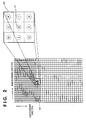
- Fig. 2 is a diagram for explaining how the raster scanning type binary image data outputted from the binary image obtaining unit 1 which is an input of the outline extractor 2 is extracted. That is, the binary image data outputted from the image obtaining unit 1 is used as input data of the outline extractor 2.
- the symbol ⁇ indicates a pixel of interest 101 of a binary image in the raster scanning and a 9-pixel area 102 including the pixel of interest and its 8 neighboring pixels is enlarged.
- the outline extractor 2 changes the pixel of interest in the raster scanning order, and detects a vector (a horizontal vector or a vertical vector) between the pixel of interest and the neighboring pixel in accordance with the state of each pixel (if a white pixel or a black pixel) in the 9-pixel area 102.
- a vector a horizontal vector or a vertical vector
- the outline vectors are connected while a rough outline vector loop is extracted.
- Fig. 3 is a diagram illustrating an example of the extraction state of the vector between a pixel of interest and the neighboring pixel.
- the symbol ⁇ represents a start point of vertical vector and the symbol " ⁇ " represents a start point of horizontal vector.
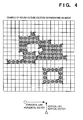
- Fig. 4 shows an example of rough outline vector loops which are extracted by the outline extractor 2.
- Each square represents a pixel position of an input image.
- Each empty square represents a white pixel, while a symbol " ⁇ " represents a black pixel. Similar to Fig. 3, the symbol ⁇ represents a start point of vertical vector and the symbol " ⁇ " represents a start point of horizontal vector.
- a rough outline vector loop is a group of outline vectors consisted of horizontal vectors and vertical vectors which are alternatively connected to each other to form an area of black pixels. As shown in Fig. 4, the outline extractor 2 extracts a rough outline vector loop so that the pixels at the right side in the vector's direction become black pixels.
- each outline vector is extracted as an intermediate position between two pixels of an input image and a line having the width of a pixel is extracted as a rough outline vector loop enclosing the pixels which form the line.
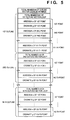
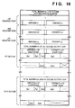
- the group of the rough vector loops extracted in the above-described way is outputted from the outline extractor 2 in the data format shown in Fig. 5.
- the data shown in Fig. 5 is comprised of the total number "N" of outline vector loops which are extracted from the image and the group of data of each outline vector loop from the first outline vector loop and the N-th outline vector loop.
- Each rough outline vector loop data is comprised of the total number of start points of vectors in a rough outline vector loop (can be considered as the total number of outline vectors) and a set of coordinates of start points of each outline vector (abscissa x, ordinate y). Each ordered pair in the set is arranged in the order that the start of a horizontal vector and that of vertical vector are alternatively arranged.
- the group of data shown in Fig. 5 is referred to as an "outline vector data table".
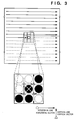
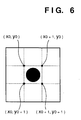
- the outline extractor 2 extracts a rough outline vector, if all neighboring pixels with respect to the black pixel of interest are white pixels, that is, if isolated point shown in Fig. 6 is extracted, the pixel of interest is not processed as a rough outline vector loop as described above, but as isolated point data in the isolated point data generator 7.
- Fig. 7 is a diagram illustrating the hardware construction of the outline processor 100 in the image processing apparatus in the embodiment.
- CPU 71 is connected to ROM 72, I/O port 73 and RAM 74 via a bus 75.
- an output of the outline extractor 2 is stored in the RAM 74 in the form of data shown in Fig. 5.
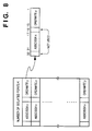
- the isolated point shown in Fig. 6 is a pixel enclosed by four points (x0, y0), (x0+1, y0), (x0+1, y0+1) and (x0, y0+1). Only the data of isolated point (x0, y0) is stored in the form shown in Fig. 8 in a storage area of isolated point data. That is, the number "k" of isolated points in image data and x-coordinate value and y-coordinate value of each isolated point are stored.
- the vector data generator 3 uses rough outline vector loop data outputted from the outline extractor 2 as input data to obtain a difference value between the coordinates of an end point and a start point determining a outline vector representing a part of an outline, and generates outline vector data by expressing the difference value in variable length.
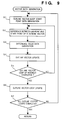
- the vector generation processing can be executed when the CPU 71 processes the procedure of Fig. 9.
- the vector generation processing in the vector data generator 3 is described below with reference to Fig. 9.
- the procedure of the flowchart in Fig. 9 is processed when the CPU 71 executes the programs stored in the ROM 72 or the RAM 74. Similar operation is needed for the other flowcharts attached to this specification.
- the coordinates of the first point of an outline vector loop of interest is determined as a start point and generates start-point coordinate value data in a fixed length to be stored in the RAM 74.
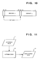
- the start-point coordinate value data is 32-bit fixed-length data as shown in Fig. 10. The most significant bits such as the 32nd bit and the 16th bit are not used, but 15 bits from the 17th bit to the 31st bit represent x-coordinates, while 15 bits from the 1st bit to the 15th bit represent y-coordinates. Accordingly, abscissa "x" and ordinate "y" of a coordinate value (x, y) are respectively represented by a 15-bit integer without sign.
- a coordinate difference value is obtained by subtracting the start-point coordinate value from the end-point coordinate value of the vector of interest.
- data is generated for the coordinate difference value. If an ordinal coordinate expression is regarded as a difference between a-position of interest and the origin, it is easily understood that the difference of the coordinate points next to each other is smaller than that of the ordinal expression. Accordingly, the coordinate expression by the difference is used as variable length data in accordance with the difference value.
- the outline vector of interest is advanced to the following vector, and it is determined whether or not the processing is performed on vectors in an outline vector loop at step S5. If not, the steps from S2 to S4 are repeated and coordinate difference value data is generated in each vector.
- the process proceeds to a new outline vector loop at step S6, and it is examined if the processing has ended for all outline vector loops. If not, the steps S1 to S6 are repeated for the new outline vector loop.
- the data of outline vector loop represented by coordinate difference values is formed.
- the data is stored as a set of ordered pairs in each outline vector loop in a similar way to the data table of Fig. 5.
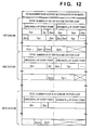
- the start point of the outline vector loop is represented by an ordinal coordinate value, and points following the start point are expressed by difference values and stored in a table.
- Fig. 12 shows the storage state of the outline vector data table. Note that both ⁇ x1 and ⁇ y1 are difference value data and variable length data.
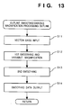
- the outline smoothing/variable magnification unit 4 is realized when the CPU 71 having the construction of Fig. 7 processes the procedure of Fig. 13. The procedure of the processing in the outline smoothing/variable magnification unit 4 is shown in Fig. 13.
- outline vector data outputted by the vector data generator 3 is received as an input.
- each outline vector is classified into a pattern based on the combination of direction and length with the preceding or following vector. Based on the pattern, outline points for the vector of interest after the first smoothing processing are defined. These outline points are points which are consisted of corner points and other representative points.
- the first smoothing processing has three features as following:
- a weighting average is calculated from coordinate values of a point of interest and the preceding or following point in each representative point except a corner point on each outline vector loop. With respect to the corner point, coordinates at the corner point themselves are used as outline point coordinate values. Weighting coefficients used for weighing average are 1/4 for the preceding or following point of interest and 1/2 for the point of interest.
- the second smoothing processing is shown in Fig. 14.
- the coordinates of the outline point before smoothing processing is expressed by Pi.
- the outline consisted of the point Qi is an outline after the second smoothing processing.
- step S14 the outline vector data on which the second smoothing processing is performed is outputted, and then the smoothing/variable magnification processing is ended.
- step S21 the smoothing/variable magnification processing (the flowchart of Fig. 13) is performed by the outline smoothing/variable magnification 4.
- step S22 it is determined if isolated data as shown in Fig. 8 exists. If existed, the process proceeds to step S23, while if not, the present processing ends.
- step S23 the isolated point developer 8 develops the isolated point data (x0, y0) to coordinate value data.
- the coordinate value data can be obtained from the isolated point data (x0, y0) are (k x x0, k y y0), (k x (x0+1), k y y0), (k x (x0+1), k y (y0+1)), (k x x0, k y (y0+1)).
- k x and k y are respectively magnification rates in the main scanning direction and the sub-scanning direction.
- the binary image reproduction unit 5 converts the outline vector data transferred via the I/O after the second smoothing processing, and outputs a binary raster scanning image of the enclosing outline vector loops.
- the outputted raster scanning type data is visualized by the binary image output unit 6 such as a video printer.
- the outline smoothing/variable magnification unit 4 sequentially obtains a needed coordinate value from the outline start-point coordinate value outputted from the vector data generator 3 and coordinate difference value of the outline vector, and performs the smoothing/variable processing after the data in difference expression is converted to the ordinal coordinate expression.
- the block diagram of the control structure of the processor where the expression by the coordinate difference value is converted to the ordinal coordinate expression is shown in Fig. 16.
- the outputs of the vector data generator 3 is inputted into the input unit 141, and the outline start-point coordinate value 142 is held in latch 145, while the difference value 143 is held in latch 144.
- the values in the latch 144 and 145 are added in the adder 146, and the obtained coordinate value is outputted to the output unit 147 and the value in the latch 145 is updated to the value obtained by the adder 146.
- an initial value of the difference value 143 is "0”
- the coordinate value 142 is outputted as a start point.
- the coordinate value outputted in this way is an input of the outline smoothing/variable magnification unit 4. This processing is executed when the CPU 71 processes control programs stored in the ROM 72.
- the binary image reproduction unit 5 converts the image into raster type data.
- the outline vector is regarded as an outline and one side of the outline vector is blackened.
- three vectors such as a vector of interest, the preceding and the following vector are required.
- Fig. 17 shows a part of the vectors comprising an outline.
- the binary image reproduction unit 5 using three continuing vectors requires four coordinate points such as P1 ⁇ P4.
- the binary image reproduction unit 5 is operated by using registers (not shown) to hold four coordinate values. These four registers delete the oldest coordinate values and use the latest coordinate values which are sequentially inputted while a vector of interest is updated.
- the processing by the binary image reproduction unit 5 can be a well-known procedure.
- the binary image output unit 6 displays an output on a CRT or prints the output by a printer based on the raster data obtained in the binary image reproduction unit 5.
- outline vectors are expressed by the difference coordinate with the neighboring points, thus compressing the vector data. Furthermore, the information concerning the isolated point data is not stored as vector data, but as position information, and this position data is developed and processed in a case of image processing. Accordingly, a storage capacity required for holding the outline vector data is reduced for the image such as a pseudo halftone image.
- the isolated data is stored in an area separated from the area for outline vector data, however, those data can be stored in the same area.
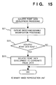
- the number of start points in an outline of the isolated data is set to "1". Selection between the processing of the isolated data and that of the outline smoothing/variable magnification processing is shown in the flowchart of Fig. 19.
- step S31 it is checked if the total number of start points in the outline is "1". If not, it means that the data is not data of an isolated point, therefore, the process proceeds to step S32 where the smoothing/variable magnification is executed for an ordinal outline vector. On the other hand, if the total number is "1", it means that the data is an isolated point data, therefore, the process proceeds to step S33 where outline vector data of isolated points is developed. Accordingly, the processing is selected between the reproduction processing of isolated vector or the conventional smoothing/variable magnification processing based on the total number of start points.
- a single image is expressed by the data of a single table by storing isolated point data in an outline vector loop table.
- the rough outline vector loop data extracted by the outline extractor 2 which is outputted from the RAM 74 of Fig. 7 is used as an input for the vector data generator 3.
- data transmission/reception can be performed between the outline extractor 2 and the vector data generator 3 through communication between I/Os. That is, the vector data generator 3 receives data from the outline extractor 2 via I/O, instead of receiving the data when all the data is prepared.
- the data includes the total number of start points in an image, the total number of start points in the first outline, the abscissa of the first start point, the ordinate of the first start point, ..., and the vector data generator 3 receives the data in this order.
- vector data can be transferred sequentially if the outline extractor 2 and the isolated point data generator 7 are connected by the I/O. Furthermore, the vector data can be transferred by not only separated I/Os, but also the same I/O.
- the vector data generator 3 can be constructed so as to generate vector data while coordinate values of following outline point are received by using the coordinate values received in the way as described above.
- the vector data generator 3 sequentially performs processing on the extracted outline vector data. Accordingly, the outline vector data is generated while outline vector loops are extracted, thus the data processing efficiency can be improved.
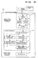
- Fig. 21 is a diagram illustrating the control structure when the image processing apparatus of the first embodiment is applied to a facsimile apparatus 210 at reception side.
- Binary image obtaining unit 1a includes a MODEM 211, code memory 212, decoder 213 and control circuit 214.
- the binary image obtaining unit 1a receives transmission data which is coded by MH coding via the MODEM 211.
- the decoder 213 decodes the received data, generates input binary image data, and transfers the data to the outline processor 215.
- the outline processor 215 includes the outline extractor 2, vector data generator 3, outline smoothing/variable magnification unit 4, binary image reproduction unit 5, isolated point data generator 7 and isolated point data developer 8, and performs the processings described in the first embodiment.
- the image data processed in the outline processor 215 is outputted to a paper by a recording apparatus 6a or displayed on a display apparatus (not shown).
- Fig. 22 is a block diagram illustrating the control structure when the image processing apparatus of the first embodiment is applied to the facsimile apparatus 220 at transmission side.
- Binary image obtaining unit 1b binarizes an image signal inputted by a scanner 221 in a binarizing unit 222 to form input image data.
- This input image data is transferred to the outline processor 227 and is subject to the processings described in the first embodiment.
- the binary image which is processed and reproduced in the outline processor 227 is stored in the image memory 223, converted to a code such as MH code by the coder 224, and transmitted via the MODEM 225.
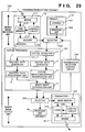
- Fig. 23 is a block diagram illustrating the control structure when the image processing apparatus of the first embodiment is applied to the facsimile apparatus 230 for transmission/reception. This is the case where the above two embodiments are combined. The portions which are identical to those in the first embodiment have the same reference numerals.
- the transmission/reception control circuit 234 shown in Fig. 23 determines an originator of image data (either the binary image obtaining unit 1a or 1b) and a designation (either the binary image output unit 6a or 6b) with respect to the outline processor 231.
- the reader 1b as a binary image obtaining unit
- the recorder 6a as a binary image output unit.
- a digital copier (or a copy mode) having a variable magnification function can be executed.
- vector data can be expressed by difference value data on which the Huffman coding is performed, instead of variable length data in accordance with the above-described difference value. This can be applied not only to this embodiment, but also the image processing apparatus of the first embodiment.
- Fig. 11 is a diagram illustrating the control structure of the difference value data generation processing.
- the Huffman coder 12 has a Huffman code table (can have a plurality of tables) in advance, and outputs vector data 13 which is coded by allotting Huffman code to the difference value 11 of each outline vector.
- the processing shown in Fig. 24 is performed before the difference value described in Fig. 16 is converted to coordinate data, and the difference value on which the Huffman coding is performed is converted to the ordinal difference value. That is, the processing described in Fig. 16 is performed after the coded vector data 241 is decoded in accordance the Huffman code table prepared in advance, and the difference value 243 of the outline vector is reproduced.
- the facsimile apparatus as described above performs a smoothing/variable magnification processing on image data in the form of outline vector data table.
- This data includes the vector expressed by the difference and isolated point value expressed by position. Accordingly, the amount of data to be held as outline vector data can be small and the required storage capacity and processing time can be reduced. This is particularly effective for pseudo halftone image data.
- the present invention can be applied to a system constituted by a plurality of devices, or to an apparatus comprising a single device. Furthermore, it goes without saying that the invention is applicable also to a case where the object of the invention is attained by supplying a program to a system or apparatus.
Landscapes
- Engineering & Computer Science (AREA)
- Multimedia (AREA)
- Physics & Mathematics (AREA)
- General Physics & Mathematics (AREA)
- Theoretical Computer Science (AREA)
- Image Processing (AREA)
- Controls And Circuits For Display Device (AREA)
Applications Claiming Priority (3)
| Application Number | Priority Date | Filing Date | Title |
|---|---|---|---|
| JP36129192 | 1992-12-28 | ||
| JP361291/92 | 1992-12-28 | ||
| JP4361291A JP2967011B2 (ja) | 1992-12-28 | 1992-12-28 | 画像処理方法及び装置 |
Publications (3)
| Publication Number | Publication Date |
|---|---|
| EP0605210A2 true EP0605210A2 (de) | 1994-07-06 |
| EP0605210A3 EP0605210A3 (de) | 1994-08-17 |
| EP0605210B1 EP0605210B1 (de) | 1999-08-04 |
Family
ID=18472977
Family Applications (1)
| Application Number | Title | Priority Date | Filing Date |
|---|---|---|---|
| EP93310484A Expired - Lifetime EP0605210B1 (de) | 1992-12-28 | 1993-12-23 | Bildverarbeitungsverfahren und -gerät |
Country Status (4)
| Country | Link |
|---|---|
| US (1) | US5515179A (de) |
| EP (1) | EP0605210B1 (de) |
| JP (1) | JP2967011B2 (de) |
| DE (1) | DE69325883T2 (de) |
Cited By (4)
| Publication number | Priority date | Publication date | Assignee | Title |
|---|---|---|---|---|
| WO2001018690A3 (en) * | 1999-09-03 | 2001-06-14 | Imagex Com Inc | Method and apparatus for normalization of image files and load balancing of operations |
| US6633890B1 (en) | 1999-09-03 | 2003-10-14 | Timothy A. Laverty | Method for washing of graphic image files |
| US6791707B2 (en) | 2000-01-10 | 2004-09-14 | Imagex, Inc. | Automated, hosted prepress applications |
| US6903839B1 (en) | 1999-09-03 | 2005-06-07 | Imagex, Inc. | Apparatus for washing of graphic image files |
Families Citing this family (10)
| Publication number | Priority date | Publication date | Assignee | Title |
|---|---|---|---|---|
| DE69433603D1 (de) * | 1993-10-26 | 2004-04-15 | Canon Kk | Bildverarbeitungsverfahren und -gerät |
| US5440407A (en) * | 1994-03-11 | 1995-08-08 | Hewlett-Packard Company | Pixel correction and smoothing method |
| US5974195A (en) * | 1994-10-14 | 1999-10-26 | Canon Kabushiki Kaisha | Image processing apparatus and method |
| JPH08179752A (ja) * | 1994-12-21 | 1996-07-12 | Canon Inc | 画像処理装置及び方法 |
| JP3560749B2 (ja) * | 1996-11-18 | 2004-09-02 | 株式会社東芝 | 画像出力装置及び画像出力のための信号処理方法 |
| US6771384B1 (en) | 2000-01-10 | 2004-08-03 | Kinko's Washington, Inc. | Imposition of graphic image files |
| JP2002133586A (ja) * | 2000-10-30 | 2002-05-10 | Matsushita Electric Ind Co Ltd | 情報送受信システムおよび情報送受信方法 |
| US7391917B2 (en) * | 2003-02-13 | 2008-06-24 | Canon Kabushiki Kaisha | Image processing method |
| US7636097B1 (en) * | 2006-02-15 | 2009-12-22 | Adobe Systems Incorporated | Methods and apparatus for tracing image data |
| JP4933404B2 (ja) * | 2007-11-07 | 2012-05-16 | キヤノン株式会社 | 画像処理装置、画像処理方法、画像処理プログラム、並びに、プログラム記録媒体 |
Family Cites Families (3)
| Publication number | Priority date | Publication date | Assignee | Title |
|---|---|---|---|---|
| US4982294A (en) * | 1987-07-24 | 1991-01-01 | Eastman Kodak Company | Apparatus for enhancing and thresholding scanned microfilm images and methods for use therein |
| JP2806961B2 (ja) * | 1989-02-22 | 1998-09-30 | 株式会社リコー | 画像符号化方法 |
| US5029226A (en) * | 1989-10-10 | 1991-07-02 | Unisys Corporation | Method and apparatus for effecting spot/void filtering of image data |
-
1992
- 1992-12-28 JP JP4361291A patent/JP2967011B2/ja not_active Expired - Fee Related
-
1993
- 1993-12-22 US US08/171,176 patent/US5515179A/en not_active Expired - Lifetime
- 1993-12-23 DE DE69325883T patent/DE69325883T2/de not_active Expired - Lifetime
- 1993-12-23 EP EP93310484A patent/EP0605210B1/de not_active Expired - Lifetime
Cited By (4)
| Publication number | Priority date | Publication date | Assignee | Title |
|---|---|---|---|---|
| WO2001018690A3 (en) * | 1999-09-03 | 2001-06-14 | Imagex Com Inc | Method and apparatus for normalization of image files and load balancing of operations |
| US6633890B1 (en) | 1999-09-03 | 2003-10-14 | Timothy A. Laverty | Method for washing of graphic image files |
| US6903839B1 (en) | 1999-09-03 | 2005-06-07 | Imagex, Inc. | Apparatus for washing of graphic image files |
| US6791707B2 (en) | 2000-01-10 | 2004-09-14 | Imagex, Inc. | Automated, hosted prepress applications |
Also Published As
| Publication number | Publication date |
|---|---|
| DE69325883D1 (de) | 1999-09-09 |
| JPH06203153A (ja) | 1994-07-22 |
| US5515179A (en) | 1996-05-07 |
| JP2967011B2 (ja) | 1999-10-25 |
| EP0605210B1 (de) | 1999-08-04 |
| DE69325883T2 (de) | 2000-01-05 |
| EP0605210A3 (de) | 1994-08-17 |
Similar Documents
| Publication | Publication Date | Title |
|---|---|---|
| EP0650287B1 (de) | Bildverarbeitungsverfahren und -gerät | |
| EP0605210B1 (de) | Bildverarbeitungsverfahren und -gerät | |
| EP0554985B1 (de) | Verfahren und Anordnung zum Erzeugen eines Konturvektors und zur Bildvergrösserung/-verkleinerung | |
| EP1349371A2 (de) | Bildverarbeitungsgerät, -programm und Speichermedium zur Speicherung dieses Programms | |
| JPH0777418B2 (ja) | 画像処理装置 | |
| EP0415513B1 (de) | Bildreduzierungssystem | |
| JPH0410765A (ja) | 画像処理装置 | |
| JP3176195B2 (ja) | 画像処理装置 | |
| JP3514050B2 (ja) | 画像処理装置 | |
| JP3085932B2 (ja) | マスクを用いた予測映像発生装置及びその装置を用いた2進映像の圧縮、伝送及び復元装置 | |
| JPH09167222A (ja) | 画像処理装置 | |
| JP3224283B2 (ja) | 予測符号化装置および予測復号化装置 | |
| JPH05342340A (ja) | 画像処理方法及びその装置 | |
| EP0357388A2 (de) | Bildcodierungsverfahren | |
| JP3045555B2 (ja) | 多階調画像情報の2値化処理方法 | |
| JP3083336B2 (ja) | 画像処理装置およびその方法 | |
| JP2845376B2 (ja) | 画素密度変換装置 | |
| JPH064658A (ja) | 画像処理方法及びその装置 | |
| JP3147246B2 (ja) | 画像処理装置及び方法 | |
| JPH05211605A (ja) | ファクシミリ通信方法及びファクシミリ装置 | |
| JPH06141169A (ja) | 画像通信装置 | |
| JP3190085B2 (ja) | 画像処理装置及び方法 | |
| JPH05211607A (ja) | 画像処理装置及び方法 | |
| JP2000078415A (ja) | 画像処理システム、画像圧縮装置、および、記録媒体 | |
| JPS6335071A (ja) | 変倍方法 |
Legal Events
| Date | Code | Title | Description |
|---|---|---|---|
| PUAI | Public reference made under article 153(3) epc to a published international application that has entered the european phase |
Free format text: ORIGINAL CODE: 0009012 |
|
| PUAL | Search report despatched |
Free format text: ORIGINAL CODE: 0009013 |
|
| AK | Designated contracting states |
Kind code of ref document: A2 Designated state(s): DE FR GB |
|
| AK | Designated contracting states |
Kind code of ref document: A3 Designated state(s): DE FR GB |
|
| 17P | Request for examination filed |
Effective date: 19950110 |
|
| 17Q | First examination report despatched |
Effective date: 19970128 |
|
| GRAG | Despatch of communication of intention to grant |
Free format text: ORIGINAL CODE: EPIDOS AGRA |
|
| GRAG | Despatch of communication of intention to grant |
Free format text: ORIGINAL CODE: EPIDOS AGRA |
|
| GRAH | Despatch of communication of intention to grant a patent |
Free format text: ORIGINAL CODE: EPIDOS IGRA |
|
| GRAH | Despatch of communication of intention to grant a patent |
Free format text: ORIGINAL CODE: EPIDOS IGRA |
|
| GRAH | Despatch of communication of intention to grant a patent |
Free format text: ORIGINAL CODE: EPIDOS IGRA |
|
| GRAA | (expected) grant |
Free format text: ORIGINAL CODE: 0009210 |
|
| AK | Designated contracting states |
Kind code of ref document: B1 Designated state(s): DE FR GB |
|
| REF | Corresponds to: |
Ref document number: 69325883 Country of ref document: DE Date of ref document: 19990909 |
|
| ET | Fr: translation filed | ||
| PLBE | No opposition filed within time limit |
Free format text: ORIGINAL CODE: 0009261 |
|
| STAA | Information on the status of an ep patent application or granted ep patent |
Free format text: STATUS: NO OPPOSITION FILED WITHIN TIME LIMIT |
|
| 26N | No opposition filed | ||
| REG | Reference to a national code |
Ref country code: GB Ref legal event code: IF02 |
|
| PGFP | Annual fee paid to national office [announced via postgrant information from national office to epo] |
Ref country code: GB Payment date: 20101223 Year of fee payment: 18 |
|
| PGFP | Annual fee paid to national office [announced via postgrant information from national office to epo] |
Ref country code: DE Payment date: 20101231 Year of fee payment: 18 |
|
| PGFP | Annual fee paid to national office [announced via postgrant information from national office to epo] |
Ref country code: FR Payment date: 20120103 Year of fee payment: 19 |
|
| GBPC | Gb: european patent ceased through non-payment of renewal fee |
Effective date: 20121223 |
|
| REG | Reference to a national code |
Ref country code: FR Ref legal event code: ST Effective date: 20130830 |
|
| REG | Reference to a national code |
Ref country code: DE Ref legal event code: R119 Ref document number: 69325883 Country of ref document: DE Effective date: 20130702 |
|
| PG25 | Lapsed in a contracting state [announced via postgrant information from national office to epo] |
Ref country code: DE Free format text: LAPSE BECAUSE OF NON-PAYMENT OF DUE FEES Effective date: 20130702 |
|
| PG25 | Lapsed in a contracting state [announced via postgrant information from national office to epo] |
Ref country code: FR Free format text: LAPSE BECAUSE OF NON-PAYMENT OF DUE FEES Effective date: 20130102 Ref country code: GB Free format text: LAPSE BECAUSE OF NON-PAYMENT OF DUE FEES Effective date: 20121223 |