EP0605322B1 - Verfahren zum Entwässern und/oder Entsalzen und gleichzeitiger Fraktionierung von einem Produktstrom eines Ölgewinnungsfeldes - Google Patents
Verfahren zum Entwässern und/oder Entsalzen und gleichzeitiger Fraktionierung von einem Produktstrom eines Ölgewinnungsfeldes Download PDFInfo
- Publication number
- EP0605322B1 EP0605322B1 EP93403192A EP93403192A EP0605322B1 EP 0605322 B1 EP0605322 B1 EP 0605322B1 EP 93403192 A EP93403192 A EP 93403192A EP 93403192 A EP93403192 A EP 93403192A EP 0605322 B1 EP0605322 B1 EP 0605322B1
- Authority
- EP
- European Patent Office
- Prior art keywords
- zone
- liquid
- phase
- distillation
- process according
- Prior art date
- Legal status (The legal status is an assumption and is not a legal conclusion. Google has not performed a legal analysis and makes no representation as to the accuracy of the status listed.)
- Expired - Lifetime
Links
- 238000000034 method Methods 0.000 title claims description 33
- 230000018044 dehydration Effects 0.000 title claims description 4
- 238000006297 dehydration reaction Methods 0.000 title claims description 4
- 239000003208 petroleum Substances 0.000 title claims 2
- 239000012071 phase Substances 0.000 claims description 77
- 239000007788 liquid Substances 0.000 claims description 50
- 238000004821 distillation Methods 0.000 claims description 48
- 239000007789 gas Substances 0.000 claims description 34
- XLYOFNOQVPJJNP-UHFFFAOYSA-N water Substances O XLYOFNOQVPJJNP-UHFFFAOYSA-N 0.000 claims description 27
- 239000000203 mixture Substances 0.000 claims description 25
- 239000007791 liquid phase Substances 0.000 claims description 23
- 239000008346 aqueous phase Substances 0.000 claims description 20
- 229930195733 hydrocarbon Natural products 0.000 claims description 13
- 150000002430 hydrocarbons Chemical class 0.000 claims description 13
- 239000004215 Carbon black (E152) Substances 0.000 claims description 9
- 238000005194 fractionation Methods 0.000 claims description 9
- 238000012856 packing Methods 0.000 claims description 6
- 238000009833 condensation Methods 0.000 claims description 5
- 230000005494 condensation Effects 0.000 claims description 5
- 238000010908 decantation Methods 0.000 claims description 5
- 150000003839 salts Chemical class 0.000 claims description 5
- 239000011552 falling film Substances 0.000 claims description 4
- 239000007792 gaseous phase Substances 0.000 claims description 3
- 230000005484 gravity Effects 0.000 claims description 2
- 238000009835 boiling Methods 0.000 claims 7
- 239000012223 aqueous fraction Substances 0.000 claims 3
- 238000011144 upstream manufacturing Methods 0.000 claims 3
- FAPWRFPIFSIZLT-UHFFFAOYSA-M Sodium chloride Chemical compound [Na+].[Cl-] FAPWRFPIFSIZLT-UHFFFAOYSA-M 0.000 claims 1
- 238000010612 desalination reaction Methods 0.000 claims 1
- 239000011780 sodium chloride Substances 0.000 claims 1
- 239000003921 oil Substances 0.000 description 54
- 238000001816 cooling Methods 0.000 description 6
- 238000011033 desalting Methods 0.000 description 5
- 230000000630 rising effect Effects 0.000 description 5
- 238000000926 separation method Methods 0.000 description 5
- 239000000470 constituent Substances 0.000 description 4
- 239000013505 freshwater Substances 0.000 description 4
- 230000006835 compression Effects 0.000 description 3
- 238000007906 compression Methods 0.000 description 3
- 230000000694 effects Effects 0.000 description 3
- 239000012530 fluid Substances 0.000 description 3
- 238000004519 manufacturing process Methods 0.000 description 3
- 239000012808 vapor phase Substances 0.000 description 3
- RWSOTUBLDIXVET-UHFFFAOYSA-N Dihydrogen sulfide Chemical compound S RWSOTUBLDIXVET-UHFFFAOYSA-N 0.000 description 2
- 230000008030 elimination Effects 0.000 description 2
- 238000003379 elimination reaction Methods 0.000 description 2
- 239000010408 film Substances 0.000 description 2
- 238000007654 immersion Methods 0.000 description 2
- 238000004381 surface treatment Methods 0.000 description 2
- 230000010337 G2 phase Effects 0.000 description 1
- 239000002253 acid Substances 0.000 description 1
- 239000007864 aqueous solution Substances 0.000 description 1
- 238000010533 azeotropic distillation Methods 0.000 description 1
- 239000000498 cooling water Substances 0.000 description 1
- 230000007797 corrosion Effects 0.000 description 1
- 238000005260 corrosion Methods 0.000 description 1
- 239000010779 crude oil Substances 0.000 description 1
- 230000008021 deposition Effects 0.000 description 1
- 238000010586 diagram Methods 0.000 description 1
- 238000010790 dilution Methods 0.000 description 1
- 239000012895 dilution Substances 0.000 description 1
- 238000007599 discharging Methods 0.000 description 1
- 229940082150 encore Drugs 0.000 description 1
- 238000000605 extraction Methods 0.000 description 1
- 239000013529 heat transfer fluid Substances 0.000 description 1
- 238000010438 heat treatment Methods 0.000 description 1
- 229910000037 hydrogen sulfide Inorganic materials 0.000 description 1
- 238000002347 injection Methods 0.000 description 1
- 239000007924 injection Substances 0.000 description 1
- 238000009434 installation Methods 0.000 description 1
- 238000009940 knitting Methods 0.000 description 1
- 238000002156 mixing Methods 0.000 description 1
- 230000006911 nucleation Effects 0.000 description 1
- 238000010899 nucleation Methods 0.000 description 1
- 239000002245 particle Substances 0.000 description 1
- 230000001737 promoting effect Effects 0.000 description 1
- 230000000717 retained effect Effects 0.000 description 1
- 239000007787 solid Substances 0.000 description 1
- 230000003068 static effect Effects 0.000 description 1
- 230000001988 toxicity Effects 0.000 description 1
- 231100000419 toxicity Toxicity 0.000 description 1
Images

Classifications
-
- B—PERFORMING OPERATIONS; TRANSPORTING
- B01—PHYSICAL OR CHEMICAL PROCESSES OR APPARATUS IN GENERAL
- B01D—SEPARATION
- B01D3/00—Distillation or related exchange processes in which liquids are contacted with gaseous media, e.g. stripping
- B01D3/06—Flash distillation
-
- B—PERFORMING OPERATIONS; TRANSPORTING
- B01—PHYSICAL OR CHEMICAL PROCESSES OR APPARATUS IN GENERAL
- B01D—SEPARATION
- B01D1/00—Evaporating
- B01D1/06—Evaporators with vertical tubes
-
- B—PERFORMING OPERATIONS; TRANSPORTING
- B01—PHYSICAL OR CHEMICAL PROCESSES OR APPARATUS IN GENERAL
- B01D—SEPARATION
- B01D3/00—Distillation or related exchange processes in which liquids are contacted with gaseous media, e.g. stripping
- B01D3/14—Fractional distillation or use of a fractionation or rectification column
- B01D3/32—Other features of fractionating columns ; Constructional details of fractionating columns not provided for in groups B01D3/16 - B01D3/30
- B01D3/322—Reboiler specifications
-
- C—CHEMISTRY; METALLURGY
- C10—PETROLEUM, GAS OR COKE INDUSTRIES; TECHNICAL GASES CONTAINING CARBON MONOXIDE; FUELS; LUBRICANTS; PEAT
- C10G—CRACKING HYDROCARBON OILS; PRODUCTION OF LIQUID HYDROCARBON MIXTURES, e.g. BY DESTRUCTIVE HYDROGENATION, OLIGOMERISATION, POLYMERISATION; RECOVERY OF HYDROCARBON OILS FROM OIL-SHALE, OIL-SAND, OR GASES; REFINING MIXTURES MAINLY CONSISTING OF HYDROCARBONS; REFORMING OF NAPHTHA; MINERAL WAXES
- C10G5/00—Recovery of liquid hydrocarbon mixtures from gases, e.g. natural gas
- C10G5/06—Recovery of liquid hydrocarbon mixtures from gases, e.g. natural gas by cooling or compressing
-
- C—CHEMISTRY; METALLURGY
- C10—PETROLEUM, GAS OR COKE INDUSTRIES; TECHNICAL GASES CONTAINING CARBON MONOXIDE; FUELS; LUBRICANTS; PEAT
- C10G—CRACKING HYDROCARBON OILS; PRODUCTION OF LIQUID HYDROCARBON MIXTURES, e.g. BY DESTRUCTIVE HYDROGENATION, OLIGOMERISATION, POLYMERISATION; RECOVERY OF HYDROCARBON OILS FROM OIL-SHALE, OIL-SAND, OR GASES; REFINING MIXTURES MAINLY CONSISTING OF HYDROCARBONS; REFORMING OF NAPHTHA; MINERAL WAXES
- C10G7/00—Distillation of hydrocarbon oils
-
- Y—GENERAL TAGGING OF NEW TECHNOLOGICAL DEVELOPMENTS; GENERAL TAGGING OF CROSS-SECTIONAL TECHNOLOGIES SPANNING OVER SEVERAL SECTIONS OF THE IPC; TECHNICAL SUBJECTS COVERED BY FORMER USPC CROSS-REFERENCE ART COLLECTIONS [XRACs] AND DIGESTS
- Y02—TECHNOLOGIES OR APPLICATIONS FOR MITIGATION OR ADAPTATION AGAINST CLIMATE CHANGE
- Y02A—TECHNOLOGIES FOR ADAPTATION TO CLIMATE CHANGE
- Y02A20/00—Water conservation; Efficient water supply; Efficient water use
- Y02A20/124—Water desalination
Definitions
- the invention relates to a dehydration and / or desalting process and for the simultaneous fractionation of an effluent from an oil field containing oil, associated gas and salty water.
- the treatment of an oilfield effluent includes generally an oil-gas fractionation step the purpose of which is adjust the bubble point of the oil produced so as to make it thermodynamically stable under storage conditions.
- Treatment also generally includes a stage of separation of an aqueous liquid phase, immiscible with the oil phase and possibly being salty; indeed, an aqueous phase is in general produced at the same time as liquid and gaseous hydrocarbons and must be disposed of to meet the water content and salt in the oil produced.
- an aqueous phase is in general produced at the same time as liquid and gaseous hydrocarbons and must be disposed of to meet the water content and salt in the oil produced.
- it is often necessary to desalinate the oil by mixing the oil with fresh water or water with salinity less than the water produced at the same time as the oil, then separate the liquid phases from water and oil.
- the treatment can also include a step of deacidification of the oil produced consisting mainly of the extraction of most of the hydrogen sulfide H 2 S for reasons of toxicity and corrosion.
- stages are generally simultaneous, the production effluent undergoing a series of successive expansions, generally 3 or 4, from the pressure leaving the effluent well to a pressure close to atmospheric pressure, with, at each expansion, elimination or recompression of the gas produced and elimination of the aqueous phase by decantation with possibly injection of fresh water between the detents to produce a desalting effect, the effluent being generally heated before the last expansion in order to meet the specifications in vapor pressure and H 2 S of the oil produced and facilitate the separation of the aqueous phase.
- the gas produced at each expansion contains heavy constituents (C + / 4) it is not necessary to remove oil to stabilize it. It is desirable to recover these heavy constituents to reinject them into oil because it increases the amount of stabilized oil produced while lowering its density, which increases its market value. In addition, the presence of these heavy constituents in the gas produced gives it a point high hydrocarbon dew prejudicial to its commercialization.
- oil-gas fractionation alone or in combination with deacidification of the oil produced, can be achieved with a high oil yield and with a substantial saving in power heating, compression power and size installation, which can be particularly important in a context such as that of offshore oil production.
- the present invention makes it possible, thanks to the separating power of the distillation, to eliminate H 2 S up to the specification for effluents containing up to several% mass of H 2 S, without losing higher hydrocarbons (C + / 4) at the head of the distillation zone.
- the effluent to be treated arrives via line 1. It is relaxed at the pressure P1 gas discharge (for example between 1 and 10 MPa) in the valve V1, from which it leaves partially vaporized through line 2 and is mixed with a liquid fraction coming from the B2 flask and arriving through the conduit 3.
- P1 gas discharge for example between 1 and 10 MPa
- the phases of the mixture thus obtained are separated in flask B1.
- the gas phase is evacuated via line 4, possibly mixed to a gas phase coming from the balloon B2 arriving via the conduit 11, and evacuated from the process.
- the aqueous phase is partly removed from the process via line 5.
- the liquid hydrocarbon phase which contains a low fraction of the non-separated aqueous phase (for example between 1% and 5%) is evacuated through line 6, then expanded in a valve V2 to a pressure P2 between the pressure P1 and the pressure atmospheric.
- the pressure P2 is for example between 0.15 and 1 MPa.
- the hydrocarbon phase leaving valve V2 via line 7 can be mixed with a quantity of fresh water circulating in the conduit 15 (this amount of water can be for example between 10 and 100% of the quantity of oil circulating in the conduit 6) in order to reduce its content salt by dilution effect; the mixture obtained is introduced (step (c)) into the distillation zone C1.
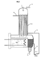
- This distillation zone includes a reboiler B101 and an internal heat exchange zone Z101, in which the liquid oil phase from step (d) and leaving said reboiling area B101, going up along said area internal heat exchange Z101, heats liquid L1 and steam flowing against the current in the distillation zone C1.
- the sentence aqueous solution injected through line 15 may preferably consist of fresh water, but also with water with a salt content lower than that of the residual aqueous phase contained in the phase oil flowing in line 6 so as to have a desalting effect.
- the reboiling area B101 consists of two parts: in the part located under the distillation zone C1, the mixture of the two phases oil and water liquids is brought to the boil by an external supply of heat, while in a side part separated by a vertical baffle and supplied by liquid overflowing over said cabinet, both liquid phases of oil and water are separated by decantation, which allows the aqueous phase to be discharged through line 14, and to the phase oil to be discharged through line 12 through pump P101.
- the temperature in reboiling area B101 is generally between 100 ° C and 250 ° C, and preferably between 100 ° C and 150 ° C.
- the distillation residue consists of an oil phase and an aqueous phase which are separated by decantation; the oil phase complies with RVP (Reid Vapor Pressure), H 2 S and, water content specifications. After rising through the internal heat exchange zone Z101, the oil phase is evacuated through line 8.
- the steam distillate is discharged through line 9; it can be at least in part recompressed in compressor K1, from pressure P2 to pressure P1, then generally cooled in the heat exchanger E1 by a fluid external may be for example water, or air, or any other fluid cooling system available on site.
- This recompression-cooling sequence condenses a liquid phase rich in higher hydrocarbons.
- the quantity of liquid fraction arriving in the distillation zone C1 via line 7 being much larger than the quantity of gas leaving via line 9, the temperature of the gas leaving the distillation zone C1 via line 9 is close to the temperature of the liquid fraction circulating in line 7; it is generally understood between 40 and 80 ° C.
- the liquid-vapor mixture thus formed is discharged from the heat exchanger. heat E1 to the balloon B2 via the conduit 10.
- the liquid fraction formed of a mixture of a liquid oil phase and an aqueous liquid phase is evacuated from the balloon B2 via line 3 and mixed with the effluent coming from valve V1 and arriving via line 2, to be sent towards balloon B1 (step (a), as already described above.
- the phase aqueous liquid obtained after condensation at the outlet of the exchanger E1 being made up of practically zero salinity water since it comes from of a condensation can be separated and reinjected through line 15 of so as to contribute to the desalting process.
- the vapor phase is evacuated from the cylinder B2 via the conduit 11 and mixed with a gaseous fraction from balloon B1 and arriving via the conduit 4, as already described above.
- Recompression of the gas phase leaving the top of column C1 can be performed in one or more stages of compression; he is however advantageous to perform this recompression in one step in order to limit the number of compressors; for this purpose we can choose the value of pressure P2 intermediate between pressure P1 and pressure atmospheric P0 and in a ratio such as for example P2 / P0 is at less than half of P1 / P2.
- the gas phase G2 recompressed at the pressure P1 could be mixed with the gas phase G1 and removed from the process directly without cooling, but it is much more advantageous to cool the gas phase G2 after recompression so as to condense part of the G2 phase and, after separation in the flask B2, to recycle the liquid phase thus obtained to the flask B1 as already previously written.
- step (c) of the process of the invention one can operate in a device as described below in connection with FIG. 2.
- the internal heat exchange zone Z101 can be produced according to different configurations, some examples of which are detailed below.
- the internal heat exchange zone Z101 can be consisting of vertical tubes in which the oil mixture to be degassed and water flows in film falling on the internal walls of the tubes while the liquid oil phase rising from the reboiling zone B101 circulates at the outside of the tubes in the grille.
- the internal wall of said tubes vertical can be smooth, but also have roughness, or have undergone a surface treatment favoring the transfer of matter and heat between the phases circulating inside the tubes, as well as the transfer of heat between the phases circulating on either side of the wall of the tubes.
- the internal surface of the tubes could have a geometry promoting the appearance of waves within the film of falling liquid, or well have grooves in the axis of the tubes so as to increase the internal surface of these, or may be coated with a deposition of agglomerated solid particles favoring the nucleation of bubbles of vapor within the falling film of liquid.
- the inner wall of the tubes is preferably wetted by the oil phase.
- Said vertical tubes can also be filled with packing loose, such as balls, rings or saddles.
- packing loose such as balls, rings or saddles.
- the largest dimension of a packing element will be less than an eighth of the diameter of said tubes.
- Said vertical tubes can also be filled with packing structured made for example of metallic canvas, metallic knitting, plates or braces as used for example in mixers static.
- Another possible configuration is to operate on the external surface of tubes the contact between the mixture of oil to be degassed and water and the steam rising from the reboiling zone B101 by the calender, the phase oil liquid rising, through the P101 pump, from the reboiling B101 from the inside of the tubes.
- the grille can be empty or filled with loose or structured packing.
- the outer surface of the tubes may be smooth or have roughness, or having undergone a surface treatment favoring the transfer of matter and heat between the phases circulating outside the tubes, as well as the heat transfer between the phases circulating on both sides of the wall of the tubes.
- the outer wall of the tubes is preferably wetted by the oil phase.
- the internal heat exchange zone Z101 can also have a structure such that the two circulation spaces are delimited by a set of vertical plates.
- the distillation device C1 may also include a device for distributing the mixture of oil to be degassed and water in the corresponding circulation space of the heat exchange zone internal Z101 when this space is multiple (for example consisting of tubes). Such devices are known to those skilled in the art.
- the effluent to be treated which is a crude oil leaving the well production, arrives via line 1 at a flow rate of 169.3 tonnes / h including 31.1 tonnes / h of free water; its temperature is 60 ° C, its pressure is 30 MPa. It is relaxed up to the pressure P1 of 3 MPa in the valve V1, from which it emerges through line 2 at a temperature of 37 ° C. He is then mixed with a liquid L3 coming from the balloon B2 through the conduit 3 under a flow rate of 2.15 tonnes / h, including 155 kg / h of free water; this liquid is at a temperature of 35 ° C and at a pressure of 3 MPa.
- the mixture thus obtained is sent to balloon B1 where the gas phase is completely separated liquid phases, which are partially separated.
- the sentence gas G1 is evacuated through line 4 at a flow rate of 72.1 tonnes / h; the liquid L1, formed of a majority hydrocarbon phase and a phase aqueous minority, is discharged through line 6 to valve V2 under a flow rate of 68.5 tonnes / h, including 321 kg / h of aqueous phase; the liquid phase aqueous is discharged from the process via line 5 at a flow rate of 30.88 ton / h.
- the liquid phase L1 is expanded to a pressure P2 of 1 MPa and partially vaporized, then mixed with an aqueous liquid phase L4 with a salinity much lower than saturation, arriving via line 15 at a flow rate of 2583 kg / h.
- Liquid phases and the vapor phase thus obtained are at a temperature of 32 ° C and enter via line 7 in the distillation zone C1 which includes a zone internal heat exchange Z101 and a reboiling zone B101.
- the temperature in reboiler B101 is 132 ° C.
- the exchange area of internal heat Z101 consists of vertical tubes in which the oil to be degassed flows in falling films on the internal walls of the tubes.
- the liquid phase anhydrous hydrocarbon L2 leaving the reboiling zone B101 through the pump P101 at 132 ° C is returned to the area internal heat exchange Z101, in which it circulates outside tubes, then it is evacuated at the head of the distillation zone C1 by the conduit 8 at 62 ° C, at a flow rate of 50.9 tonnes / h.
- the aqueous phase is totally decanted in reboiler B101 and discharged from the process by the conduit 14 at a flow rate of 2736 kg / h.
- the vapor phase G2 is evacuated from the head of the distillation zone C1 by the conduit 9 under a flow rate of 17.45 tonnes / h at a temperature of 53 ° C.
- the gas phase G2 enters compressor K1, whose power is 520 kW, hence it comes out at a pressure of 3 MPa and at a temperature of 110 ° C and between in the heat exchanger E1.
- the phase carbonated gas G2 is cooled to 35 ° C by external cooling water to the process, this cooling causing the condensation of a fraction gas in the form of an L3 liquid.
- the mixture is discharged from the exchanger heat E1 through line 10 and sent to balloon B2, in which the gas phase is separated from liquid phases.
- the L3 liquid formed liquid hydrocarbon and aqueous phases is mixed with the fluid from from valve V1 through line 2, the gas phase is evacuated through the line 11 and mixed with the gas phase G1 flowing in line 4, and the gas phase resulting from this mixture is evacuated at temperature of 36 ° C with a flow rate of 87.4 tonnes / h.
Landscapes
- Chemical & Material Sciences (AREA)
- Chemical Kinetics & Catalysis (AREA)
- Oil, Petroleum & Natural Gas (AREA)
- Engineering & Computer Science (AREA)
- General Chemical & Material Sciences (AREA)
- Organic Chemistry (AREA)
- Production Of Liquid Hydrocarbon Mixture For Refining Petroleum (AREA)
- Vaporization, Distillation, Condensation, Sublimation, And Cold Traps (AREA)
- Organic Low-Molecular-Weight Compounds And Preparation Thereof (AREA)
Claims (18)
- Verfahren zur Dehydratisierung und/oder Entsalzung und gleichzeitiger Fraktionierung eines Erdöllagerstättenabstroms, der öl, zugehöriges Gas und gegebenenfalls salziges Wasser enthält, dadurch gekennzeichnet, daß es umfaßt:(a) wenigstens eine Stufe zur Trennung der flüssigen und gasförmigen Phasen beim Gasabzugsdruck P1, derart, daß einerseits eine gasförmige Fraktion G1, die abgezogen wird und andererseits eine flüssige Fraktion L1, die zur Stufe (b) geschickt wird, erzeugt wird;(b) wenigstens eine Stufe zur wenigstens teilweisen Trennung der beiden flüssigen Phasen im Gemisch in der flüssigen Fraktion L1, wobei die wässrige Phase partiell abgezogen wird und die ölphase, die eine Menge an wässriger Restphase enthält, zur Stufe (c) geleitet wird;(c) wenigstens eine Destillationsstufe, die bei einem Druck P2 kleiner oder gleich dem Druck P1 der Stufe (a) in einer Destillationszone C1 betrieben wird, wobei diese Destillation in Anwesenheit der aus der Stufe (b) stammenden ölphase durchgeführt wird, diese Zone C1 eine innere Wärmeaustauscherzone und eine Abkochzone umfaßt und es ermöglicht, einerseits eine gasförmige Fraktion G2 und andererseits eine flüssige Fraktion L2 zu sammeln, wobei diese Fraktion L2 gebildet wird aus einer flüssigen ölförmigen Phase und einer flüssigen wässrigen Phase, die mit der flüssigen ölphase nicht mischbar ist, und(d) wenigstens eine Stufe zur Trennung der beiden flüssigen Phasen im Gemisch in der flüssigen Fraktion L2, wobei die ölförmige Phase in diese Zone des inneren Wärmeaustausches geleitet und dann abgezogen wird.
- Verfahren nach Anspruch 1, dadurch gekennzeichnet, daß die Stufe (c) bei einem Druck P2 zwischen dem Druck P1, bei der die Stufe (a) betrieben wird und dem atmosphärischen Druck P0 realisiert wird, wobei das Verhältnis P2/P0 wenigstens gleich der Hälfte des Verhältnisses P1/P2 ist.
- Verfahren nach einem der Ansprüche 1 bis 2, dadurch gekennzeichnet, daß eine wässrige Fraktion dem aus der Stufe (b) stammenden Gemisch vor seinem Eintritt in die Stufe (c) zugesetzt wird.
- Verfahren nach Anspruch 3, dadurch gekennzeichnet, daß die zugesetzte wässrige dem aus der Stufe (b) stammenden Gemisch vor ihrem Eintritt in die Stufe (c) zugesetzte Fraktion eine Konzentration aus Salz hat, die kleiner ist als die, die in der aus der Stufe (b) stammenden wässrigen Restphase existiert.
- Verfahren nach einem der Ansprüche 1 bis 4, dadurch gekennzeichnet, daß die gasförmige Fraktion G2 rekomprimiert, dann gekühlt und wenigstens zum Teil kondensiert wird, wobei die erhaltene flüssige Fraktion ein Gemisch einer Phase aus Kohlenwasserstoffen und einer wässrigen Phase, die voneinander getrennt werden, ist, wobei die Kohlenwasserstoffphase zur Stufe (a) im Kreislauf rückgeführt wird.
- Verfahren nach Anspruch 5, dadurch gekennzeichnet, daß die wässrige gemäß Anspruch 3 zugegebene Fraktion wenigstens zum Teil aus der wässrigen Phase stammt, die durch partielle Kondensation der gasförmigen Phase G2 erhalten wurde.
- Verfahren nach einem der Ansprüche 1 bis 6, dadurch gekennzeichnet, daß die Kochtemperatur der Destillation der Stufe (c) zwischen 100°C und 150°C liegt.
- Verfahren nach einem der Ansprüche 1 bis 7, dadurch gekennzeichnet, daß die Abzugstemperatur der gasförmigen Phase G2 am Kopf der Destillationszone C1 zwischen 40 und 80°C liegt.
- Verfahren nach einem der Ansprüche 1 bis 8, dadurch gekennzeichnet, daß die ölförmige aus der flüssigen Fraktion L2 stammende Phase von unten nach oben in der inneren Wärmeaustauscherzone, allgemein im Gegenstrom zur flüssigen Phase L1, die in der Destillationszone nach unten geht, zirkuliert.
- Verfahren nach einem der Ansprüche 1 bis 9, dadurch gekennzeichnet, daß die Destillationsstufe (c) in einer Destillationszone C1 realisiert wird, die eine innere Wärmeaustauscherzone umfaßt, welche zwei Zirkulationsräume aufweist, die aus vertikalen Rohren sowie einen diese Rohre umschließenden Kalander, gebildet sind.
- Verfahren nach Anspruch 10, dadurch gekennzeichnet, daß das Gemisch der beiden die flüssige Fraktion L1 bildenden Phasen im fallenden Film in den Rohren fließt.
- Verfahren nach Anspruch 11, dadurch gekennzeichnet, daß die ölförmige Phase von unten nach oben auf der Außenwand der Rohre zirkuliert.
- Verfahren nach einem der Ansprüche 11 und 12, dadurch gekennzeichnet, daß das Gemisch der beiden die flüssige Fraktion L1 bildenden Phasen im Inneren der vertikalen mit einer Füllung oder Auskleidung gefüllten Rohren strömt.
- Verfahren nach Anspruch 10, dadurch gekennzeichnet, daß das Gemisch der beiden die flüssige Fraktion L1 bildenden Phasen im fallenden Film außerhalb der Rohre strömt.
- Verfahren nach Anspruch 14, dadurch gekennzeichnet, daß die ölphase von unten nach oben auf der Innenwand der Rohre zirkuliert.
- Verfahren nach einem der Ansprüche 14 und 15, dadurch gekennzeichnet, daß das Gemisch der beiden die flüssige Fraktion L1 bildenden Phasen in dem mit einer Füllung versehenen Kalander strömt.
- Verfahren nach einem der Ansprüche 1 bis 9, dadurch gekennzeichnet, daß diese Destillationsstufe (c) in einer Destillationszone C1, die eine innere Wärmeaustauscherzone umfaßt, realisiert wird, welche zwei durch eine Anordnung vertikaler Platten begrenzte Zirkulationsräume umfaßt.
- Apparat zur Realisierung der Stufen (c) und (d) des Verfahrens nach einem der Ansprüche 1 bis 17, eine Abkochzone umfassend, die von einer Destillationszone überlagert wird und dadurch gekennzeichnet, daßdiese Abkochzone gebildet wird durch einen Ballon, der einerseits einen Behälter umfaßt, der das Eintauchen in den Rest der Destillation einer Abkochvorrichtung ermöglicht und andererseits, getrennt durch ein vertikales Baffle von dem vorhergehenden Behälter eine Dekantierungszone, die für die Trennung einer flüssigen ölphase und einer flüssigen wässrigen Phase geeignet ist, sowie Mittel zum Abzug der wässrigen Phase, sowie Mittel zum Abzug dieser flüssigen ölphase vermittels einer Pumpe;und daß diese Destillationszone eine innere Wärmeaustauscherzone, bestehend aus zwei Zirkulationsräumen umfaßt;wobei einer dieser Zirkulationsräume für die Schwerkraftströmung des zu entgasenden Gemisches und des Wassers, das am Kopf dieser Destillationszone ankommt, im Gegenstrom zu dem aus der Kochzone aufsteigenden Dampf durch diese innere Wärmeaustauscherzone eingerichtet ist und für den Abzug dieses Dampfs am Kopf dieser Destillations- und Wärmeaustauscherzone ausgelegt ist;wobei der andere Zirkulationsraum zur Strömung von unten nach oben der flüssigen aus der Abkochzone austretenden ölphase vermittels der Pumpe ausgelegt ist und in die Wärmeaustauscherzone wieder eintritt und für den Abzug dieser flüssigen ölphase am Kopf dieser Destillations- und Wärmeaustauscherzone ausgelegt ist.
Applications Claiming Priority (2)
| Application Number | Priority Date | Filing Date | Title |
|---|---|---|---|
| FR9216032 | 1992-12-30 | ||
| FR9216032A FR2699959B1 (fr) | 1992-12-30 | 1992-12-30 | Procédé de déshydratation et/ou dessalage et de fractionnement simultané d'un effluent de gisement pétrolier. |
Publications (2)
| Publication Number | Publication Date |
|---|---|
| EP0605322A1 EP0605322A1 (de) | 1994-07-06 |
| EP0605322B1 true EP0605322B1 (de) | 1998-07-08 |
Family
ID=9437380
Family Applications (1)
| Application Number | Title | Priority Date | Filing Date |
|---|---|---|---|
| EP93403192A Expired - Lifetime EP0605322B1 (de) | 1992-12-30 | 1993-12-28 | Verfahren zum Entwässern und/oder Entsalzen und gleichzeitiger Fraktionierung von einem Produktstrom eines Ölgewinnungsfeldes |
Country Status (6)
| Country | Link |
|---|---|
| US (1) | US5456823A (de) |
| EP (1) | EP0605322B1 (de) |
| CA (1) | CA2112639C (de) |
| DK (1) | DK0605322T3 (de) |
| FR (1) | FR2699959B1 (de) |
| NO (1) | NO302402B1 (de) |
Families Citing this family (9)
| Publication number | Priority date | Publication date | Assignee | Title |
|---|---|---|---|---|
| US11260316B2 (en) * | 2002-11-13 | 2022-03-01 | Deka Products Limited Partnership | Pressurized vapor cycle liquid distillation |
| US7597784B2 (en) * | 2002-11-13 | 2009-10-06 | Deka Products Limited Partnership | Pressurized vapor cycle liquid distillation |
| DE202009018910U1 (de) * | 2009-11-16 | 2014-07-02 | H2O Gmbh | Trennanordnung |
| US10435307B2 (en) * | 2010-08-24 | 2019-10-08 | Private Equity Oak Lp | Evaporator for SAGD process |
| US8904668B2 (en) * | 2012-10-11 | 2014-12-09 | Eastman Kodak Company | Applying heating liquid to remove moistening liquid |
| US9677006B2 (en) | 2013-06-24 | 2017-06-13 | Fluor Technologies Corporation | Multiple preflash and exchanger (MPEX) network system for crude and vacuum units |
| WO2015109402A1 (en) | 2014-01-21 | 2015-07-30 | 1Nsite Technologies Ltd. | Evaporator sump and process for separating contaminants resulting in high quality steam |
| RU2613556C1 (ru) * | 2016-01-18 | 2017-03-17 | Виль Файзулович Галиакбаров | Устройство для обессоливания и обезвоживания нефти |
| US10874957B2 (en) | 2019-01-23 | 2020-12-29 | Saudi Arabian Oil Company | Methods for desalinating aqueous compositions through hetero-azeotropic distillation |
Family Cites Families (8)
| Publication number | Priority date | Publication date | Assignee | Title |
|---|---|---|---|---|
| US2725342A (en) * | 1951-08-25 | 1955-11-29 | Lummus Co | Distillation |
| US3121056A (en) * | 1960-08-01 | 1964-02-11 | Gas Proc Inc | Method and apparatus for stabilizing natural gasoline |
| US3425935A (en) * | 1964-10-09 | 1969-02-04 | Exxon Research Engineering Co | Distillation in the presence of water |
| US3441499A (en) * | 1965-09-23 | 1969-04-29 | Combustion Eng | Method for treating crude petroleum production |
| US3453205A (en) * | 1967-03-08 | 1969-07-01 | Combustion Eng | Method and means for field-processing crude petroleum production |
| FR2311571A1 (fr) * | 1975-05-20 | 1976-12-17 | Kestner App Evaporateurs | Evaporateur a multiple effet isobar |
| US4082653A (en) * | 1976-11-17 | 1978-04-04 | Degraff Richard Raymond | Crude oil distillation process |
| FR2680200B1 (fr) * | 1991-08-08 | 1993-10-29 | Institut Francais Petrole | Procede de fractionnement d'huile et de gaz sur un effluent de gisement petrolier. |
-
1992
- 1992-12-30 FR FR9216032A patent/FR2699959B1/fr not_active Expired - Fee Related
-
1993
- 1993-12-28 NO NO934856A patent/NO302402B1/no not_active IP Right Cessation
- 1993-12-28 EP EP93403192A patent/EP0605322B1/de not_active Expired - Lifetime
- 1993-12-28 DK DK93403192T patent/DK0605322T3/da active
- 1993-12-30 CA CA002112639A patent/CA2112639C/fr not_active Expired - Fee Related
- 1993-12-30 US US08/176,480 patent/US5456823A/en not_active Expired - Lifetime
Also Published As
| Publication number | Publication date |
|---|---|
| EP0605322A1 (de) | 1994-07-06 |
| CA2112639A1 (fr) | 1994-07-01 |
| FR2699959A1 (fr) | 1994-07-01 |
| NO934856D0 (no) | 1993-12-28 |
| CA2112639C (fr) | 2004-07-27 |
| DK0605322T3 (da) | 1999-02-01 |
| NO934856L (no) | 1994-07-01 |
| NO302402B1 (no) | 1998-03-02 |
| US5456823A (en) | 1995-10-10 |
| FR2699959B1 (fr) | 1995-09-29 |
Similar Documents
| Publication | Publication Date | Title |
|---|---|---|
| US11168262B2 (en) | Integrated gas oil separation plant for crude oil and natural gas processing | |
| EP1415965B1 (de) | Verfahren zur Regenerierung einer Salze enthaltenden wässrigen Lösung von Glykol | |
| EP0796134B1 (de) | Verfahren zum behandeln von erdgas, das wasser und kondensierbare kohlenwasserstoffe enthält | |
| EP0768502B1 (de) | Verfahren und Vorrichtung zur Verflüssigung und Behandlung von Erdgas | |
| CA2230092C (fr) | Procede de desacidification avec production de gaz acides en phase liquide | |
| FR2822838A1 (fr) | Procede de deshydratation et de fractionnement d'un gaz naturel basse pression | |
| CA2112639C (fr) | Procede de deshydratation et/ou de fractionnement simultane d'un effluent de gisement petrolier | |
| FR2808460A1 (fr) | Procede et dispositif de separation d'au moins un gaz acide contenu dans un melange gazeux | |
| FR2757423A1 (fr) | Procede et dispositif de traitement d'un gaz par refrigeration et mise en contact avec un solvant | |
| US9752827B2 (en) | Method and system of maintaining a liquid level in a distillation tower | |
| EP0530062B1 (de) | Verfahren zum Fraktionieren von Öl und Gas aus einem Produktstrom eines Ölgewinnungsfeldes | |
| CA2378677C (fr) | Procede ameliore de deshydratation et de degazolinage d'un gaz naturel humide | |
| RU2106903C1 (ru) | Установка улавливания паров нефтепродуктов | |
| EP3727648B1 (de) | Verfahren zum destillieren eines sauerstoffhaltigen gasstroms | |
| FR2793701A1 (fr) | Procede de production d'oxygene gazeux | |
| EP0768106B1 (de) | Verfahren zur Fraktionierung eines mehrere trennbare Komponenten enthaltenden Fluids wie z.B. Erdgas | |
| EP2937125A1 (de) | Aufbereitungsverfahren einer wässrigen Lösung mit gelösten Substanzen durch Kristallisation von hydrierten Klathraten | |
| CA1187033A (fr) | Procede de recuperation d'une fraction hydrocarbonee en c.sub.3-c.sub.7 a partir d'un melange liquide de ladite fraction avec une huile desasphaltee | |
| RU2063576C1 (ru) | Устройство для подготовки к транспорту нефтяного газа и способ подготовки нефтяного газа | |
| CH200057A (fr) | Procédé de fabrication de l'urée. | |
| BE438425A (de) | ||
| FR2607718A1 (fr) | Procede de fractionnement d'un melange liquide utilisant un echangeur de chaleur a plaques comme colonne de fractionnement et son application a la production de gaz de petrole liquefie | |
| FR2463890A1 (fr) | Procede de pre-chauffage de l'eau d'alimentation d'une chaudiere au moyen de vapeurs d'hydrocarbures | |
| CH140424A (fr) | Procédé pour préparer, en partant d'hydrocarbures lourds, des hydrocarbures plus légers, et installation pour sa mise en oeuvre. | |
| BE571426A (de) |
Legal Events
| Date | Code | Title | Description |
|---|---|---|---|
| PUAI | Public reference made under article 153(3) epc to a published international application that has entered the european phase |
Free format text: ORIGINAL CODE: 0009012 |
|
| AK | Designated contracting states |
Kind code of ref document: A1 Designated state(s): DK GB IT NL |
|
| 17P | Request for examination filed |
Effective date: 19950109 |
|
| 17Q | First examination report despatched |
Effective date: 19970416 |
|
| GRAG | Despatch of communication of intention to grant |
Free format text: ORIGINAL CODE: EPIDOS AGRA |
|
| GRAG | Despatch of communication of intention to grant |
Free format text: ORIGINAL CODE: EPIDOS AGRA |
|
| GRAH | Despatch of communication of intention to grant a patent |
Free format text: ORIGINAL CODE: EPIDOS IGRA |
|
| ITF | It: translation for a ep patent filed | ||
| GRAH | Despatch of communication of intention to grant a patent |
Free format text: ORIGINAL CODE: EPIDOS IGRA |
|
| GRAA | (expected) grant |
Free format text: ORIGINAL CODE: 0009210 |
|
| AK | Designated contracting states |
Kind code of ref document: B1 Designated state(s): DK GB IT NL |
|
| GBT | Gb: translation of ep patent filed (gb section 77(6)(a)/1977) |
Effective date: 19980722 |
|
| REG | Reference to a national code |
Ref country code: DK Ref legal event code: T3 |
|
| PLBE | No opposition filed within time limit |
Free format text: ORIGINAL CODE: 0009261 |
|
| STAA | Information on the status of an ep patent application or granted ep patent |
Free format text: STATUS: NO OPPOSITION FILED WITHIN TIME LIMIT |
|
| 26N | No opposition filed | ||
| REG | Reference to a national code |
Ref country code: GB Ref legal event code: IF02 |
|
| PGFP | Annual fee paid to national office [announced via postgrant information from national office to epo] |
Ref country code: DK Payment date: 20031223 Year of fee payment: 11 |
|
| PG25 | Lapsed in a contracting state [announced via postgrant information from national office to epo] |
Ref country code: DK Free format text: LAPSE BECAUSE OF NON-PAYMENT OF DUE FEES Effective date: 20050103 |
|
| REG | Reference to a national code |
Ref country code: DK Ref legal event code: EBP |
|
| PG25 | Lapsed in a contracting state [announced via postgrant information from national office to epo] |
Ref country code: IT Free format text: LAPSE BECAUSE OF NON-PAYMENT OF DUE FEES;WARNING: LAPSES OF ITALIAN PATENTS WITH EFFECTIVE DATE BEFORE 2007 MAY HAVE OCCURRED AT ANY TIME BEFORE 2007. THE CORRECT EFFECTIVE DATE MAY BE DIFFERENT FROM THE ONE RECORDED. Effective date: 20051228 |
|
| PGFP | Annual fee paid to national office [announced via postgrant information from national office to epo] |
Ref country code: NL Payment date: 20091224 Year of fee payment: 17 |
|
| PGFP | Annual fee paid to national office [announced via postgrant information from national office to epo] |
Ref country code: GB Payment date: 20091231 Year of fee payment: 17 |
|
| REG | Reference to a national code |
Ref country code: NL Ref legal event code: V1 Effective date: 20110701 |
|
| GBPC | Gb: european patent ceased through non-payment of renewal fee |
Effective date: 20101228 |
|
| PG25 | Lapsed in a contracting state [announced via postgrant information from national office to epo] |
Ref country code: GB Free format text: LAPSE BECAUSE OF NON-PAYMENT OF DUE FEES Effective date: 20101228 |
|
| PG25 | Lapsed in a contracting state [announced via postgrant information from national office to epo] |
Ref country code: NL Free format text: LAPSE BECAUSE OF NON-PAYMENT OF DUE FEES Effective date: 20110701 |