EP0605341B1 - Appareil pour le couplage des boucles FDDI - Google Patents
Appareil pour le couplage des boucles FDDI Download PDFInfo
- Publication number
- EP0605341B1 EP0605341B1 EP93480174A EP93480174A EP0605341B1 EP 0605341 B1 EP0605341 B1 EP 0605341B1 EP 93480174 A EP93480174 A EP 93480174A EP 93480174 A EP93480174 A EP 93480174A EP 0605341 B1 EP0605341 B1 EP 0605341B1
- Authority
- EP
- European Patent Office
- Prior art keywords
- surrogate
- token
- ring
- counter
- stations
- Prior art date
- Legal status (The legal status is an assumption and is not a legal conclusion. Google has not performed a legal analysis and makes no representation as to the accuracy of the status listed.)
- Expired - Lifetime
Links
- 239000000835 fiber Substances 0.000 title description 3
- 239000000872 buffer Substances 0.000 claims description 11
- 230000005540 biological transmission Effects 0.000 description 10
- 238000010586 diagram Methods 0.000 description 4
- 230000003287 optical effect Effects 0.000 description 2
- 230000003068 static effect Effects 0.000 description 2
- 108700026140 MAC combination Proteins 0.000 description 1
- 230000003139 buffering effect Effects 0.000 description 1
- 230000001934 delay Effects 0.000 description 1
- 230000001788 irregular Effects 0.000 description 1
- 238000000034 method Methods 0.000 description 1
- 239000013307 optical fiber Substances 0.000 description 1
- 230000008054 signal transmission Effects 0.000 description 1
- 238000004088 simulation Methods 0.000 description 1
Images


Classifications
-
- H—ELECTRICITY
- H04—ELECTRIC COMMUNICATION TECHNIQUE
- H04L—TRANSMISSION OF DIGITAL INFORMATION, e.g. TELEGRAPHIC COMMUNICATION
- H04L12/00—Data switching networks
- H04L12/28—Data switching networks characterised by path configuration, e.g. LAN [Local Area Networks] or WAN [Wide Area Networks]
- H04L12/46—Interconnection of networks
- H04L12/4604—LAN interconnection over a backbone network, e.g. Internet, Frame Relay
- H04L12/462—LAN interconnection over a bridge based backbone
- H04L12/4625—Single bridge functionality, e.g. connection of two networks over a single bridge
-
- H—ELECTRICITY
- H04—ELECTRIC COMMUNICATION TECHNIQUE
- H04L—TRANSMISSION OF DIGITAL INFORMATION, e.g. TELEGRAPHIC COMMUNICATION
- H04L12/00—Data switching networks
- H04L12/28—Data switching networks characterised by path configuration, e.g. LAN [Local Area Networks] or WAN [Wide Area Networks]
- H04L12/46—Interconnection of networks
- H04L12/4637—Interconnected ring systems
Definitions
- the present invention generally relates to local area networks (LANs) and, more particularly, to networks using a timed token protocol and to interconnecting devices on such networks, such as servers, bridges, and routers.
- LANs local area networks
- networks using a timed token protocol and to interconnecting devices on such networks, such as servers, bridges, and routers.
- the OSI model defines seven layers -- from the physical link dealing with mechanical, electrical and optical characteristics of signals to the application layer which provides file transfer and network management services to users.
- Local area network (LAN) standards within the OSI model are the subject matter and constraints for the present invention.
- Local area networks are characterized by a topology (e.g ring or bus) for connecting devices to the LAN's signal transmission medium (e.g. cable or optical fiber) and a protocol (e.g. token-ring or timed-token) for controlling access to the medium by an attached device.
- Communication capacity over a LAN is limited by the transmission medium, and also by the topology and the relevant protocols at both the physical and media access control levels.
- Bitwidth is a measure of the communication capacity of a LAN, and is commonly given in bits per second. For example, the bandwidth of a coaxial cable Ethernet LAN may be 10 million bits per second (Mbps) while a Fiber optical Distributed Data Interface (FDDI) Lan using a timed-token protocol may be 100 Mbps.
- FDDI Fiber optical Distributed Data Interface
- a further object of the invention is to reduce the delay, buffering, and packet loss across a bridge/router.
- a further object of the invention to increase throughput by circulating multiple tokens through different sections of the network.
- An additional object of the invention is to increase the chance of a successful transmission and to improve reliability.
- the above objectives can be achieved by constructing a bridge/router such that it effectively behaves as one or more virtual stations on each of the LANs it connects to, as shown in Figure 4. This may be based on the number of station on each LAN or the traffic patterns between LANs.
- the present invention is an apparatus for interconnecting networks that utilize a token based protocol (e.g., Fiber optic Distributed Data Interface or FDDI) so as to increase the effective bandwidth available to a station, remaining in conformance with standards.
- a token based protocol e.g., Fiber optic Distributed Data Interface or FDDI
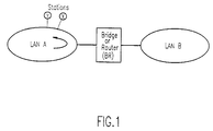
- Bridges and routers have been used for establishing communication links between stations on different networks.
- a summary of prior art of bridges and routers is published in IEEE Network Magazine, January 1988-Vol. 2, No. 1, pp. 57-64, and in the Handbook of Computer Communications Standards, By W. Stallings, Vol. 2, pp. 207-234. These describe the operation of a bridge between two LANs, A and B, as shown in Figure 1. This operation is summarized as follows:
- Each bridge is a single station on each of the networks that it connects to and transmits frames onto the network in accordance with a media access control (MAC) protocol. This is shown in Figure 2.
- MAC media access control
- a router reads only packets explicitly addressed to it and determines the LAN onto which it should be transmitted. Thus, as in the bridge case, frames may arrive faster than they can be transmitted.
- a router is also a single station on each of the networks to which it is connected.
- the amount of time available to a bridge or a router (indicated by BR in Figure 3) for transmission is the same as that for any other station on the LAN.
- the time available for a conventional bridge/router to transmit data is shown in Figure 3.
- the bridge/router may start transmission of packets and can transmit for up to full target token rotation time (TTRT) (point 2 in Figure 3), before releasing the token.
- TTRT target token rotation time
- station X can transmit for up to a full TTRT and so on.
- the bridge/router will act as if it is N B virtual stations on LAN A and N A virtual stations on LAN B, as illustrated in Figure 4.
- the bandwidth available to station X on LAN A for transmission to LAN B over the bridge/router will be same as if the station X was on LAN B.
- the bridge/router has N B *TTRT seconds of transmission time on LAN A while other stations (station X in Figure 1) have only TTRT seconds transmission time (out of ⁇ N A + N B * TTRT ⁇ seconds).
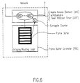
- the ring interface of such an apparatus comprises:
- a static determination of the maximum value for the Surrogate Counter SC max can be achieved by identifying the number of stations connected to each LAN using Station Management (SMT) capability and using a fraction of the number of stations to set the value of SC max .
- SMT Station Management
- this apparatus is especially desirable within a bride/router where several stations on one side of the bridge/router are represented on the opposite side ring through the bridge/router. Those stations being represented by the bridge/router will appear, to all other stations on the ring, as though they are physically attached to the ring. Consequently, the bridge/router has bandwidth available for all the stations that it connects to (represents). However, it does not have to incur the costs of true physical connections that the additional attachments would require would they actually be attached to the ring (e.g., latency, BER, etc.).
- a counter, SC must be initialized to the number of stations that are to be represented.
- SC surrogate counter
- the bridge/router determines the amount of asynchronous bandwidth available and transmits data for that duration given by ATRT (until point 2 in Figure 5). Once the timer expires the token is released and SC is decremented (point 2 in Figure 5). If SC > 0, then the bridge/router's ATRT timer is reset.
- the bridge/router may again capture the token as though it were the next station on the surrogate counter (SC) list (point 3 in Figure 5).
- SC surrogate counter
- SC will be set to the number of stations the bridge/router represents (SC max ). By adjusting SC max , any number of stations can be represented. In order to avoid violating the FDDI Standards, a surrogate should not represent more stations than are actually attached to the LAN.
- the number of stations that bridge/router represents may be adjusted statically or dynamically. For the static determination, using station management (SMT) capability of FDDI, the bridge/router will determine the exact number of stations on each of the LANs it connects to. Then, a predetermined fraction of that number (representative of the inter-LAN traffic) will be used to initialize the value of SC.
- SMT station management
- the value of SC may be adjusted dynamically based on the state of the buffers in the bridge/router.
- Two threshold values, T H and T L may be used for the buffers. When the buffer occupancy exceeds T H , SC max is incremented and when buffer occupancy goes below T L , SC max is decremented.
- the predetermined upper and lower bounds may be used to ensure certain service criteria (for example SC max should be at least one).
Landscapes
- Engineering & Computer Science (AREA)
- Computer Networks & Wireless Communication (AREA)
- Signal Processing (AREA)
- Small-Scale Networks (AREA)
Claims (3)
- Dispositif pour ajuster la largeur de bande asynchrone rendue disponible à une station de substitution (BR) fonctionnant dans à la fois un premier (A) et un second (B) anneau de stations dans un réseau de communication employant un protocole de jetons synchronisés caractérisé en ce qu'il comprend :un compteur de substitution (SC) présentant une valeur maximale, ledit compteur de substitution étant réinitialisé à ladite valeur maximale lorsque ladite station de substitution envoie un jeton sans le capturer, ledit compteur de substitution étant décrémenté de un lorsque ladite station de substitution envoie un jeton après l'avoir capturé ; etun élément d'accès au support (MAE) comportant un temporisateur de rotation de jeton ajustable (ATRT), ledit temporisateur étant réinitialisé lorsque ladite station de substitution détecte un jeton, ledit temporisateur étant de nouveau réinitialisé lorsque ladite station de substitution envoie un jeton, si le compteur de substitution est supérieur à zéro.
- Dispositif selon la revendication 1, ladite valeur maximale étant le nombre de stations à partir dudit second anneau (B) représenté sur ledit premier anneau par ladite station de substitution (BR), ledit nombre représenté étant une fraction prédéterminée du nombre total de stations sur ledit second anneau, ladite fraction prédéterminée étant choisie de sorte que ledit nombre représenté est représentatif d'un trafic de communication entre ledit premier anneau et ledit second anneau.
- Dispositif selon la revendication 1, comprenant en outre une mémoire tampon de données pour mémoriser le trafic de communication en débordement entre ledit premier anneau (A) et ledit second anneau (B) et un moyen de seuil pour mémoriser une valeur de seuil élevée pour la quantité de données mémorisées dans ladite mémoire tampon de données, de sorte que lorsque ladite valeur de seuil élevée est dépassée, ladite valeur maximale dudit compteur de substitution (SC) est incrémentée, ledit moyen de seuil mémorisant en outre une valeur de seuil faible, de sorte que lorsque ladite valeur de seuil faible dépasse la quantité de données mémorisées dans ladite mémoire tampon de données, ladite valeur maximale dudit compteur de substitution est décrémentée, ladite valeur maximale n'étant jamais décrémentée au-dessous d'une valeur minimale de un.
Applications Claiming Priority (2)
| Application Number | Priority Date | Filing Date | Title |
|---|---|---|---|
| US07/997,796 US5337311A (en) | 1992-12-29 | 1992-12-29 | Apparatus for connecting two fiber distributed data interface rings |
| US997796 | 1992-12-29 |
Publications (3)
| Publication Number | Publication Date |
|---|---|
| EP0605341A2 EP0605341A2 (fr) | 1994-07-06 |
| EP0605341A3 EP0605341A3 (fr) | 1995-02-15 |
| EP0605341B1 true EP0605341B1 (fr) | 1999-08-25 |
Family
ID=25544405
Family Applications (1)
| Application Number | Title | Priority Date | Filing Date |
|---|---|---|---|
| EP93480174A Expired - Lifetime EP0605341B1 (fr) | 1992-12-29 | 1993-11-04 | Appareil pour le couplage des boucles FDDI |
Country Status (4)
| Country | Link |
|---|---|
| US (1) | US5337311A (fr) |
| EP (1) | EP0605341B1 (fr) |
| JP (1) | JP2502927B2 (fr) |
| DE (1) | DE69326133T2 (fr) |
Families Citing this family (13)
| Publication number | Priority date | Publication date | Assignee | Title |
|---|---|---|---|---|
| DE4307174A1 (de) * | 1993-03-08 | 1994-09-15 | Philips Patentverwaltung | Lokales Netzwerk |
| GB9319937D0 (en) * | 1993-09-28 | 1993-11-17 | Madge Networks Ltd | Ring communication system and method |
| EP0658025A1 (fr) * | 1993-12-08 | 1995-06-14 | International Business Machines Corporation | Système à haute disponibilité d'allocation de bande passante synchrone sur FDDI |
| US5754549A (en) * | 1995-12-05 | 1998-05-19 | International Business Machines Corporation | Inexpensive two-way communications switch |
| DK0831947T3 (da) | 1996-04-02 | 2002-12-23 | Disetronic Licensing Ag | Indsprøjtningsindretning |
| US6687221B1 (en) | 1997-02-21 | 2004-02-03 | Fujitsu Limited | Communication management control system, communication control unit therefor and computer program product |
| EP1001574A1 (fr) * | 1998-11-10 | 2000-05-17 | International Business Machines Corporation | Méthode et système dans un réseau de commutation de paquets pour l'ajustement dynamique de la largeur de bande d'une voie virtuelle, en fonction de la charge du réseau |
| JP3388541B2 (ja) * | 1999-06-28 | 2003-03-24 | 日本電気株式会社 | ダイヤルアップルータとそのルータにおける発信制御方法 |
| US8799206B2 (en) * | 2005-02-07 | 2014-08-05 | Mimosa Systems, Inc. | Dynamic bulk-to-brick transformation of data |
| US8812433B2 (en) * | 2005-02-07 | 2014-08-19 | Mimosa Systems, Inc. | Dynamic bulk-to-brick transformation of data |
| US8918366B2 (en) * | 2005-02-07 | 2014-12-23 | Mimosa Systems, Inc. | Synthetic full copies of data and dynamic bulk-to-brick transformation |
| EP1938215A4 (fr) * | 2005-08-23 | 2009-11-25 | Mimosa Systems Inc | Disponibilite de service d'entreprise par preservation d'identite |
| US8483236B2 (en) * | 2007-07-31 | 2013-07-09 | Intel Corporation | Dynamic bandwidth allocation for multiple virtual MACs |
Family Cites Families (3)
| Publication number | Priority date | Publication date | Assignee | Title |
|---|---|---|---|---|
| US4587651A (en) * | 1983-05-04 | 1986-05-06 | Cxc Corporation | Distributed variable bandwidth switch for voice, data, and image communications |
| JPH06103888B2 (ja) * | 1989-10-14 | 1994-12-14 | 三菱電機株式会社 | 通信レスポンス制御方法 |
| US5051986A (en) * | 1989-12-01 | 1991-09-24 | National Semiconductor Corporation | Asynchronous priority select logic |
-
1992
- 1992-12-29 US US07/997,796 patent/US5337311A/en not_active Expired - Fee Related
-
1993
- 1993-11-04 DE DE69326133T patent/DE69326133T2/de not_active Expired - Fee Related
- 1993-11-04 EP EP93480174A patent/EP0605341B1/fr not_active Expired - Lifetime
- 1993-11-26 JP JP5296285A patent/JP2502927B2/ja not_active Expired - Fee Related
Also Published As
| Publication number | Publication date |
|---|---|
| JPH06237260A (ja) | 1994-08-23 |
| DE69326133T2 (de) | 2000-03-30 |
| EP0605341A2 (fr) | 1994-07-06 |
| US5337311A (en) | 1994-08-09 |
| JP2502927B2 (ja) | 1996-05-29 |
| EP0605341A3 (fr) | 1995-02-15 |
| DE69326133D1 (de) | 1999-09-30 |
Similar Documents
| Publication | Publication Date | Title |
|---|---|---|
| EP0487235B1 (fr) | Gestion de la bande passante et de la congestion pour l'accès à des réseaux à intégration de services à large bande | |
| Suter et al. | Design considerations for supporting TCP with per-flow queueing | |
| Lefelhocz et al. | Congestion control for best-effort service: why we need a new paradigm | |
| CA2179618C (fr) | Interface de liaison de donnes pour reseau de commutation par paquets | |
| Anjum et al. | Balanced-RED: An algorithm to achieve fairness in the Internet | |
| EP0605341B1 (fr) | Appareil pour le couplage des boucles FDDI | |
| US7630309B1 (en) | Systems and methods for limiting the rates of data to/from a buffer | |
| JPH10233802A (ja) | Tcp接続の性能改善方法 | |
| US7197051B1 (en) | System and method for efficient packetization of ATM cells transmitted over a packet network | |
| US7573821B2 (en) | Data packet rate control | |
| Doshi et al. | Congestion Control in ISDN Frame‐Relay Networks | |
| Gerla et al. | Flow control protocols | |
| Wechta et al. | The interaction of the TCP flow control procedure in end nodes on the proposed flow control mechanism for use in IEEE 802.3 switches | |
| McAlpine et al. | An architecture for congestion management in Ethernet clusters | |
| Tzeng et al. | Performance of TCP over UBR in ATM with EPD and virtual queuing techniques | |
| Siu et al. | Performance of TCP over ATM with time-varying available bandwidth | |
| Gu et al. | Rate based congestion control over high bandwidth/delay links | |
| Wu et al. | Ack filtering on bandwidth asymmetry networks | |
| Hassan et al. | Performance Comparison of ATM LAN with FDDI and Fast Ethernet | |
| Welzel | Performance comparison of service strategies in high speed optical token rings | |
| Nagata et al. | An analysis of the impact of suspending cell discarding in TCP-over-ATM | |
| Monteiro et al. | A fairness analysis of LAN/WAN protocol relays | |
| Aweya et al. | Improving network service quality with explicit TCP window control | |
| Fulton et al. | Impact analysis of packet-level scheduling on an ATM shared-memory switch | |
| Morgan et al. | Packet-pair rate control—buffer requirements and overload performance |
Legal Events
| Date | Code | Title | Description |
|---|---|---|---|
| PUAI | Public reference made under article 153(3) epc to a published international application that has entered the european phase |
Free format text: ORIGINAL CODE: 0009012 |
|
| AK | Designated contracting states |
Kind code of ref document: A2 Designated state(s): DE FR GB |
|
| 17P | Request for examination filed |
Effective date: 19941021 |
|
| PUAL | Search report despatched |
Free format text: ORIGINAL CODE: 0009013 |
|
| AK | Designated contracting states |
Kind code of ref document: A3 Designated state(s): DE FR GB |
|
| 17Q | First examination report despatched |
Effective date: 19980515 |
|
| GRAG | Despatch of communication of intention to grant |
Free format text: ORIGINAL CODE: EPIDOS AGRA |
|
| GRAG | Despatch of communication of intention to grant |
Free format text: ORIGINAL CODE: EPIDOS AGRA |
|
| GRAH | Despatch of communication of intention to grant a patent |
Free format text: ORIGINAL CODE: EPIDOS IGRA |
|
| GRAH | Despatch of communication of intention to grant a patent |
Free format text: ORIGINAL CODE: EPIDOS IGRA |
|
| GRAA | (expected) grant |
Free format text: ORIGINAL CODE: 0009210 |
|
| AK | Designated contracting states |
Kind code of ref document: B1 Designated state(s): DE FR GB |
|
| REF | Corresponds to: |
Ref document number: 69326133 Country of ref document: DE Date of ref document: 19990930 |
|
| ET | Fr: translation filed | ||
| PLBE | No opposition filed within time limit |
Free format text: ORIGINAL CODE: 0009261 |
|
| STAA | Information on the status of an ep patent application or granted ep patent |
Free format text: STATUS: NO OPPOSITION FILED WITHIN TIME LIMIT |
|
| 26N | No opposition filed | ||
| REG | Reference to a national code |
Ref country code: GB Ref legal event code: IF02 |
|
| PGFP | Annual fee paid to national office [announced via postgrant information from national office to epo] |
Ref country code: FR Payment date: 20031120 Year of fee payment: 11 |
|
| PGFP | Annual fee paid to national office [announced via postgrant information from national office to epo] |
Ref country code: GB Payment date: 20041123 Year of fee payment: 12 |
|
| PGFP | Annual fee paid to national office [announced via postgrant information from national office to epo] |
Ref country code: DE Payment date: 20041125 Year of fee payment: 12 |
|
| PG25 | Lapsed in a contracting state [announced via postgrant information from national office to epo] |
Ref country code: FR Free format text: LAPSE BECAUSE OF NON-PAYMENT OF DUE FEES Effective date: 20050729 |
|
| REG | Reference to a national code |
Ref country code: FR Ref legal event code: ST |
|
| PG25 | Lapsed in a contracting state [announced via postgrant information from national office to epo] |
Ref country code: GB Free format text: LAPSE BECAUSE OF NON-PAYMENT OF DUE FEES Effective date: 20051104 |
|
| PG25 | Lapsed in a contracting state [announced via postgrant information from national office to epo] |
Ref country code: DE Free format text: LAPSE BECAUSE OF NON-PAYMENT OF DUE FEES Effective date: 20060601 |
|
| GBPC | Gb: european patent ceased through non-payment of renewal fee |
Effective date: 20051104 |