EP0605909A1 - Steuerungseinrichtung - Google Patents
Steuerungseinrichtung Download PDFInfo
- Publication number
- EP0605909A1 EP0605909A1 EP93203360A EP93203360A EP0605909A1 EP 0605909 A1 EP0605909 A1 EP 0605909A1 EP 93203360 A EP93203360 A EP 93203360A EP 93203360 A EP93203360 A EP 93203360A EP 0605909 A1 EP0605909 A1 EP 0605909A1
- Authority
- EP
- European Patent Office
- Prior art keywords
- mechanical system
- compensation
- output signal
- controller
- control unit
- Prior art date
- Legal status (The legal status is an assumption and is not a legal conclusion. Google has not performed a legal analysis and makes no representation as to the accuracy of the status listed.)
- Granted
Links
Images


Classifications
-
- G—PHYSICS
- G05—CONTROLLING; REGULATING
- G05B—CONTROL OR REGULATING SYSTEMS IN GENERAL; FUNCTIONAL ELEMENTS OF SUCH SYSTEMS; MONITORING OR TESTING ARRANGEMENTS FOR SUCH SYSTEMS OR ELEMENTS
- G05B19/00—Program-control systems
- G05B19/02—Program-control systems electric
- G05B19/18—Numerical control [NC], i.e. automatically operating machines, in particular machine tools, e.g. in a manufacturing environment, so as to execute positioning, movement or co-ordinated operations by means of program data in numerical form
- G05B19/19—Numerical control [NC], i.e. automatically operating machines, in particular machine tools, e.g. in a manufacturing environment, so as to execute positioning, movement or co-ordinated operations by means of program data in numerical form characterised by positioning or contouring control systems, e.g. to control position from one programmed point to another or to control movement along a programmed continuous path
Definitions
- the invention relates to a controller for controlling a non-linear mechanical system having a plurality of degrees of freedom.
- a degree of freedom is a possibility of the mechanical system to move in a certain direction, like a translation along a x-,y- and/or z-axis or a rotation around an x-,y- and/or z-axis.
- a mechanical system can have a plurality of degrees of freedom, which need to be controlled to obtain a desired position or rotation.
- Such a controller is used to realise for example accurate positioning of a mechanical system.
- Examples of such mechanical systems can be found in both consumer products (so-called CD-players, DCC-players) and in industrial production equipment (wafersteppers, component-placement-equipment).
- Many mechanical systems are subject to friction and/or backlash, which makes it difficult to position the mechanical system accurate. Instead of demanding higher accuracy of the mechanical system, which inevitably leads to more expensive components, a controller can be used.
- controllers which controls the non-linear aspects of the mechanical system, like friction and backlash, and which accurate position a mechanical system are not known.
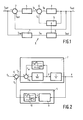
- This controller is characterized in that the controller comprises a subtracter for subtracting an output signal of the mechanical system from a setpoint signal, the output signal of the subtracter being the input signal of a control unit of the controller, the controller further comprises compensation means to compensate the non-linear behaviour of the mechanical system, the controller further comprises an adder for adding an output signal of the compensation means to an output signal of the control unit, the output signal of the adder being the input signal of the mechanical system, the controller further comprises a reference model of both the control unit and the linearized mechanical system, the setpoint signal being an input signal of the reference model, and the controller further comprises adaptation means which adapt the compensation means in dependence on a difference between the output signal of the mechanical system and the output signal of the reference model.
- the reference model which is a model of the control unit and the linearized mechanical system, receives the same setpoint signals as the control unit and the non-linear mechanical system. Assuming that the reference model gives a good description of the linear part of the mechanical system, the difference between the output of the reference model and the non-linear mechanical system originates from the non-linear part of the mechanical system.
- the compensation means comprises a model of the non-linear part of the mechanical system. Based on the output signal of the mechanical system, the compensation means adds a compensation signal to the output signal of the control unit.
- the adaptation means adapts the model of the compensation means as long as the difference between the output of the reference model and the output of the non-linear mechanical system is not zero.
- Another advantage of adaptation of the compensation is that temperature, wear and time dependence of the non-linear part of the mechanical system are taken into account.
- An embodiment of the controller according to the invention is characterized in that the non-linear behaviour of the mechanical system is due to Coulomb-friction which compensated for by the compensation means, whereby the output signal of the compensation means represents a compensation force F e , which depends on the direction of a velocity V of the mechanical system according to: whereby E is a velocity below which accurate determination of the direction of the velocity is not possible, d, c 2 are compensation values, and the compensation force F c is added to a force output signal F s of the control unit.
- Coulomb-friction is friction which can be described as a constant friction force which opposes the motion of the mechanical system, when the velocity of the mechanical system is not zero.
- a relatively small dead zone E around zero velocity is used, because the direction of the velocity can only be determined when the mechanical system is moving with a minimum velocity E .
- the friction can be described as Coulomb-friction.
- a correct determination of the value c i , c 2 of the compensation is very important: if the compensation is smaller than the friction present, no full suppression of the friction effect will take place; if the compensation is greater than the friction present, limit cycling will occur.
- the compensation is determined according to another embodiment of the controller according to the invention, which is characterized in that the adaptation means adapt the compensation values c i , c 2 by calculating a remaining force F r , which depends on a difference between a position output signal of the mechanical system and a position output signal of the reference model, after which new values for c 1 and C2 are calculated according to
- the adaptation means will strive to reduce the remaining force F r to zero all the time, in which case full compensation takes place. It this way a high position accuracy is obtained.
- the model of the compensation means is only adapted when the velocity is larger E . When the velocity is smaller than E , the direction of the compensation might be adapted if the desired accuracy is not yet obtained.
- the compensation is determined according to a further embodiment of the controller according to the invention, which is characterized in that the adaptation means adapt the compensation values c 1 , c 2 by calculating a remaining force F r , which depends on a difference between a position output signal of the mechanical system and a position output signal of the reference model, after which new values for c 1 and C2 are calculated according to if
- ⁇ Ethan c 1 and c2 are not changed and F c 0 with
- the adaptation means will strive to reduce the remaining force F r to zero all the time, in which case full compensation takes place.
- the adaptation is very easy and the obtained position accuracy is good.
- control unit comprises proportional and derivative feedback.
- Such a control unit can easily be implemented and is relatively fast.
- control unit comprises integral feedback.
- An embodiment of the controller according to the invention is characterized in that acceleration terms in the remaining force F, are neglected by the adaptation means.
- the transfer function H vel comprises a differentiator (s) followed by a second order low pass filter
- the transfer function H acc comprises a double differentiator (s 2 ) followed by the same second order low pass filter.
- the low pass filter can be characterized by a crossover frequency f dif and a relative damping ⁇ dif .
- Figure 5 shows the complete controller 1 for controlling the mechanical system 2 of figure 2.
- the controller 1 comprises the mechanical system 2 and the compensation means 5 of figure 2 and the control unit 4 and the reference model 7 of figure 3.
- the controller 1 further comprises adaptation means 8. With the adaptation means 8 a difference between the real position x of the mechanical system 2 and the calculated position x m is calculated.
- the difference (x m -x) is caused by residual non-linear forces F r , which are not compensated for by the compensation means 5.
- the residual forces are determined as follows: whereby H acc represents a transfer function of a differentiating network 22, which is used to estimate the acceleration ⁇ est .
- the sign of F r depends on the direction of the velocity ⁇ est of the mechanical system 2 and on the values of the compensation and friction. Multiplication of F r by the sign of the velocity, sign( ⁇ est ), yields the variable F, sign( ⁇ est ), the sign of which is independent of the direction of the speed.
- the parameters c 1 and c 2 and the compensation force F c are adapted as follows: if
- ⁇ than F c 0 with
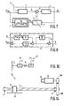
- Figure 6 shows a part of another controller according to the invention, comprising a control unit 4, a mechanical system 2 and compensation means 5.
- the mechanical system 2 represents a rotating mass with an inertia J which is rotated in ⁇ -direction, whereby a Coulomb-torque T f opposes the rotation of the mass.
- the system 2 is denoted in the Laplace-transform.
- the control unit 4 comprises a proportional action kp acting on a difference ⁇ set - ⁇ , between an position setpoint signal ⁇ set and a position output signal ⁇ .
- the control unit 4 further comprises a differentiating action H vel k v acting only on the position ⁇ , whereby H vel represents a transfer function of a differentiating network 22 according to figure 4, which is used to estimate the velocity ; est of the mass of the mechanical system 2.
- H vel represents a transfer function of a differentiating network 22 according to figure 4, which is used to estimate the velocity ; est of the mass of the mechanical system 2.
- the transfer function is
- the compensation means 5 also comprises the transfer function H vel for estimating the velocity ; est .
- the compensation means 5 further comprises a model 10 of the non-linear mechanical part of the mechanical system 2.
- the torque T c is added to a torque T s of the control unit 4.
- Figure 7 shows another controller 1 according to the invention with the control unit 4, the mechanical system 2 and the compensation means 5 of figure 6.
- the compensation means 5 of figure 6 are integrated with adaptation means of the controller 1 in one unit 11.
- the controller 1 further comprises a reference model 7 comprising a model of both the control unit 4 and the linearized part of the mechanical system 2.
- the position output signal ⁇ m of the reference model 7 would be the same as the position output signal ⁇ of the mechanical system 2 if no friction T f would occur in the mechanical system 2.
- a residual torque T r is calculated based on a difference between the position ⁇ of the mechanical system 2 and the position ⁇ m of the reference model 7 according to:
- H acc represents a transfer function of a differentiating network 22, which is used to estimate the acceleration ⁇ est , whereby
- FIG. 8 shows a PID-control unit 12 of a controller 1 according to the invention, which can be used instead of the control unit 4 of figure 6 in the controller 1 of figure 7.
- the control unit 12 comprises a proportional (P) action kp acting on the difference of ⁇ set - ⁇ , an integrating (I) action whereby k i is an integral control parameter, and a differentiating (D) action H vel k v acting only on the position ⁇ , whereby H vel represents a transfer function of a differentiating network 22, which is used to estimate the velocity ; est of the mass of the mechanical system 2. Due to the integral action an additional torque T ki is applied to the mechanical system 2. If the reference model 7 of figure 7 remains the same, the remaining torque T r will be:
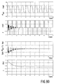
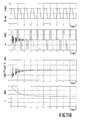
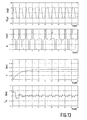
- Figure 9a shows the results of a simulation, whereby the compensation and adaptation unit 11 is disabled. Due to the friction a static position error e of 0,05 (rad) will remain.
- the static position error decreases in time to zero.
- no adaptation of the compensation takes place if the velocity is zero (if ⁇ set is constant).
- the position error shows limit cycling due to the over- compensation of the friction.
- Figure 10 shows a simplified model of a mechanical system 13, which can be described as a fourth order system.
- the mechanical system 13 comprises two inertias J 1 , J 2 , whereby J 2 is much smaller than J 1 , and a stiffness K 1 between the inertias J 1 ,J 2 .
- the controller 1 of figure 7 is used, with the control unit 4 of figure 6 and whereby the mechanical system 2 is replaced by the mechanical system 13.
- the position ⁇ 1 is used in the controller 1. Further it is assumed that friction only acts on the first inertia J 1 .
- the reference model 7 is not adapted, for the value of the inertia J, J 1 + J 2 is taken.
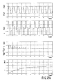
- the figures 11 a-b show the results of a simulation with the mechanical system 13.
- the static position error decreases in time to zero.
- no adaptation of the compensation takes place if the velocity is zero (if ⁇ set is constant).
- the static position error decreases in time to zero.
- no adaptation of the compensation takes place if the velocity is zero (if ⁇ set is constant).
- the compensation value c 0 and the position error due to the friction is nullified by the integral torque T ki .
- the static position error is almost zero from the beginning.
- the friction T f is compensated by the compensation value c and the integral torque T ki is used to guarantee the desired position accuracy in a short time.
- the compensation value c is used to permanently compensate the friction T f whilst the integral torque T ki is used to reduce the static position error.
- Figure 14 shows a mechanical system 14, which has been used for experiments with the controller 1 according to the invention.
- the mechanical system 14 comprises a slide 15 which is connected to a ball nut 16.
- the ball nut 16 is movable along a spindle 17 which is driven by a motor 18 via a gearwheel transmission, comprising two gearwheels 19a,b.
- the angular position ⁇ of the motor 18 is measured with an encoder 20.
- the spindle 17 is carried by two beings 21.
- a model of the mechanical system 14 is shown in figure 10.
- a controller 1 for controlling the angular position ⁇ of the motor 18 a controller 1 according to the invention is used, comprising the control unit 4 of figure 8.
- the fourth order system of figure 10 is simplified to a second order system as shown in figure 7.
- the reference model 7 only comprises the proportional and differentiating actions but not the integral action of the control unit 4. If the mechanical system 14 is not moving, the velocity ; est should be equal to zero. Due to noise, however, the velocity detection can be distorted. Therefore, it is implemented in the controller 1 that the absolute value of the velocity has to exceed a certain value ⁇ before movement is detected.
- the compensation of the compensation means and adaptation unit 11 of the controller 1 works as follows: if
- the mechanical system 14 are subject to friction between all the moving parts.
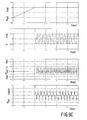
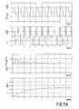
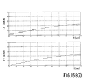
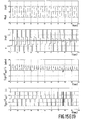
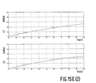
- the figures 15a-f show the results of different experiments with a controller 1 comprising the mechanical system 14 of figure 14, the reference model 7 and the compensation and adaptation unit 11 of figure 7 with the above mentioned adaptation rules, and the control unit 12 of figure 8.
- FIG 15a shows the result of an experiment, whereby the compensation and adaptation unit 11 and the integral action of the control unit 4 are disabled.
- FIG 15b shows the result of an experiment, whereby the compensation and adaptation unit 11 is enabled, whilst the integral action of the control unit 4 is disabled.
- FIG 15d shows the result of an experiment, whereby the compensation and adaptation means are enabled, whilst the integral action of the control unit 4 is disabled.
- FIG 15e shows the result of an experiment, whereby the compensation and adaptation means are enabled, whilst the integral action of the control unit 4 is disabled.
- FIG. 15f shows the result of an experiment, whereby the compensation and adaptation means and the integral action of the control unit 4 are enabled.
- the static position error is reduced smoothly within the desired accuracy a. This happens very fast and without any problems.
- the position error is nullified without overshoot.
Landscapes
- Engineering & Computer Science (AREA)
- Human Computer Interaction (AREA)
- Manufacturing & Machinery (AREA)
- Physics & Mathematics (AREA)
- General Physics & Mathematics (AREA)
- Automation & Control Theory (AREA)
- Feedback Control In General (AREA)
- Control Of Position Or Direction (AREA)
Priority Applications (1)
| Application Number | Priority Date | Filing Date | Title |
|---|---|---|---|
| EP19930203360 EP0605909B1 (de) | 1992-12-07 | 1993-12-01 | Steuerungseinrichtung |
Applications Claiming Priority (3)
| Application Number | Priority Date | Filing Date | Title |
|---|---|---|---|
| EP92203795 | 1992-12-07 | ||
| EP92203795 | 1992-12-07 | ||
| EP19930203360 EP0605909B1 (de) | 1992-12-07 | 1993-12-01 | Steuerungseinrichtung |
Publications (2)
| Publication Number | Publication Date |
|---|---|
| EP0605909A1 true EP0605909A1 (de) | 1994-07-13 |
| EP0605909B1 EP0605909B1 (de) | 1997-11-19 |
Family
ID=26131839
Family Applications (1)
| Application Number | Title | Priority Date | Filing Date |
|---|---|---|---|
| EP19930203360 Expired - Lifetime EP0605909B1 (de) | 1992-12-07 | 1993-12-01 | Steuerungseinrichtung |
Country Status (1)
| Country | Link |
|---|---|
| EP (1) | EP0605909B1 (de) |
Cited By (3)
| Publication number | Priority date | Publication date | Assignee | Title |
|---|---|---|---|---|
| WO1996016360A1 (de) * | 1994-11-19 | 1996-05-30 | Leica Lasertechnik Gmbh | Vorrichtung und verfahren zur regelung der bewegung eines gegenstandes |
| ES2149686A1 (es) * | 1998-03-31 | 2000-11-01 | Univ Catalunya Politecnica | Linealizador adaptativo para amplificadores de potencia. |
| EP0852030B1 (de) * | 1995-09-22 | 2002-07-03 | Rosemount Inc. | Adaptiver versatzregler |
Citations (4)
| Publication number | Priority date | Publication date | Assignee | Title |
|---|---|---|---|---|
| JPS57106904A (en) * | 1980-12-23 | 1982-07-03 | Fanuc Ltd | Characteristics detection system of numeric control machine tool |
| EP0128355A2 (de) * | 1983-06-13 | 1984-12-19 | Allied Corporation | Bewegungskontrolle für einen Manipulator |
| EP0170478A2 (de) * | 1984-07-30 | 1986-02-05 | Westinghouse Brake And Signal Company Limited | Stellgliedsystem |
| EP0196417A2 (de) * | 1985-03-30 | 1986-10-08 | Kabushiki Kaisha Toshiba | Regeleinrichtung für ein nichtlineares mechanisches System mit mehreren Freiheitsgraden |
-
1993
- 1993-12-01 EP EP19930203360 patent/EP0605909B1/de not_active Expired - Lifetime
Patent Citations (4)
| Publication number | Priority date | Publication date | Assignee | Title |
|---|---|---|---|---|
| JPS57106904A (en) * | 1980-12-23 | 1982-07-03 | Fanuc Ltd | Characteristics detection system of numeric control machine tool |
| EP0128355A2 (de) * | 1983-06-13 | 1984-12-19 | Allied Corporation | Bewegungskontrolle für einen Manipulator |
| EP0170478A2 (de) * | 1984-07-30 | 1986-02-05 | Westinghouse Brake And Signal Company Limited | Stellgliedsystem |
| EP0196417A2 (de) * | 1985-03-30 | 1986-10-08 | Kabushiki Kaisha Toshiba | Regeleinrichtung für ein nichtlineares mechanisches System mit mehreren Freiheitsgraden |
Non-Patent Citations (3)
| Title |
|---|
| "BASICS OF MACHINE CONTROL", MACHINE DESIGN, vol. 64, no. 12, June 1992 (1992-06-01), CLEVELAND US, pages 9 - 48 * |
| C.T. JOHNSON & R.D. LORENZ: "EXPERIMENTAL IDENTIFICATION OF FRICTION AND ITS COMPENSATION IN PRECISE, POSITION CONTROLLED MECHANISMS", CONFERENCE RECORD OF THE 1991 IEEE INDUSTRY APPLICATIONS SOCIETY ANNUAL MEETING, vol. 2, USA, pages 1400 - 1406 * |
| PATENT ABSTRACTS OF JAPAN vol. 6, no. 198 (P - 147) 7 October 1982 (1982-10-07) * |
Cited By (3)
| Publication number | Priority date | Publication date | Assignee | Title |
|---|---|---|---|---|
| WO1996016360A1 (de) * | 1994-11-19 | 1996-05-30 | Leica Lasertechnik Gmbh | Vorrichtung und verfahren zur regelung der bewegung eines gegenstandes |
| EP0852030B1 (de) * | 1995-09-22 | 2002-07-03 | Rosemount Inc. | Adaptiver versatzregler |
| ES2149686A1 (es) * | 1998-03-31 | 2000-11-01 | Univ Catalunya Politecnica | Linealizador adaptativo para amplificadores de potencia. |
Also Published As
| Publication number | Publication date |
|---|---|
| EP0605909B1 (de) | 1997-11-19 |
Similar Documents
| Publication | Publication Date | Title |
|---|---|---|
| US4727303A (en) | Positional control method and system utilizing same | |
| Komada et al. | Disturbance observer-based motion control of direct drive motors | |
| US5719479A (en) | Collision detecting method | |
| US4338659A (en) | Position control system for a closed loop type numerical-controlled machine tool | |
| KR100442034B1 (ko) | 모터제어장치 | |
| US5272423A (en) | Velocity control method for a synchronous AC servo motor | |
| JP3506157B2 (ja) | 電動機の位置制御装置 | |
| JP3129622B2 (ja) | フルクローズド・ループ方式における象限突起補正方法 | |
| US5374884A (en) | Model-based position-repeatable disturbance compensation | |
| US20030097193A1 (en) | Position control system and velocity control system for stage driving mechanism | |
| US5532565A (en) | Controller | |
| Yan et al. | Theory and application of a combined self-tuning adaptive control and cross-coupling control in a retrofit milling machine | |
| Song et al. | A sliding‐mode based smooth adaptive robust controller for friction compensation | |
| JPH07104856A (ja) | 振動制御方法 | |
| US9876448B2 (en) | Position control apparatus | |
| Lim et al. | Torsional displacement compensation in position control for machining centers | |
| Xu et al. | Synthesized sliding mode and time-delay control for a class of uncertain systems | |
| JP2000330642A (ja) | ステージの位置制御装置及び速度制御装置 | |
| WO2018077593A1 (en) | Method for determining a deadzone angle of a backlash in a mechanical drive-train system, method for controlling a drive motor controller as well as drive-train system | |
| EP0605909A1 (de) | Steuerungseinrichtung | |
| Horng et al. | Rejection of limit cycles induced from disturbance observers in motion control | |
| JP2838578B2 (ja) | モータ制御装置、外乱負荷トルク推定装置 | |
| JPH04142604A (ja) | サーボモータの制御方式 | |
| Komada et al. | Motion control of linear synchronous motors based on disturbance observer | |
| JP4038659B2 (ja) | サーボ制御装置 |
Legal Events
| Date | Code | Title | Description |
|---|---|---|---|
| PUAI | Public reference made under article 153(3) epc to a published international application that has entered the european phase |
Free format text: ORIGINAL CODE: 0009012 |
|
| AK | Designated contracting states |
Kind code of ref document: A1 Designated state(s): DE FR GB IT |
|
| RAP1 | Party data changed (applicant data changed or rights of an application transferred) |
Owner name: N.V. PHILIPS' GLOEILAMPENFABRIEKEN |
|
| 17P | Request for examination filed |
Effective date: 19950113 |
|
| 17Q | First examination report despatched |
Effective date: 19960415 |
|
| GRAG | Despatch of communication of intention to grant |
Free format text: ORIGINAL CODE: EPIDOS AGRA |
|
| GRAH | Despatch of communication of intention to grant a patent |
Free format text: ORIGINAL CODE: EPIDOS IGRA |
|
| GRAH | Despatch of communication of intention to grant a patent |
Free format text: ORIGINAL CODE: EPIDOS IGRA |
|
| GRAA | (expected) grant |
Free format text: ORIGINAL CODE: 0009210 |
|
| AK | Designated contracting states |
Kind code of ref document: B1 Designated state(s): DE FR GB IT |
|
| PG25 | Lapsed in a contracting state [announced via postgrant information from national office to epo] |
Ref country code: IT Free format text: LAPSE BECAUSE OF FAILURE TO SUBMIT A TRANSLATION OF THE DESCRIPTION OR TO PAY THE FEE WITHIN THE PRESCRIBED TIME-LIMIT;WARNING: LAPSES OF ITALIAN PATENTS WITH EFFECTIVE DATE BEFORE 2007 MAY HAVE OCCURRED AT ANY TIME BEFORE 2007. THE CORRECT EFFECTIVE DATE MAY BE DIFFERENT FROM THE ONE RECORDED. Effective date: 19971119 Ref country code: FR Free format text: LAPSE BECAUSE OF FAILURE TO SUBMIT A TRANSLATION OF THE DESCRIPTION OR TO PAY THE FEE WITHIN THE PRESCRIBED TIME-LIMIT Effective date: 19971119 |
|
| REF | Corresponds to: |
Ref document number: 69315318 Country of ref document: DE Date of ref document: 19980102 |
|
| PG25 | Lapsed in a contracting state [announced via postgrant information from national office to epo] |
Ref country code: GB Free format text: LAPSE BECAUSE OF NON-PAYMENT OF DUE FEES Effective date: 19980219 |
|
| PG25 | Lapsed in a contracting state [announced via postgrant information from national office to epo] |
Ref country code: DE Free format text: LAPSE BECAUSE OF FAILURE TO SUBMIT A TRANSLATION OF THE DESCRIPTION OR TO PAY THE FEE WITHIN THE PRESCRIBED TIME-LIMIT Effective date: 19980220 |
|
| EN | Fr: translation not filed | ||
| RAP4 | Party data changed (patent owner data changed or rights of a patent transferred) |
Owner name: KONINKLIJKE PHILIPS ELECTRONICS N.V. |
|
| PLBE | No opposition filed within time limit |
Free format text: ORIGINAL CODE: 0009261 |
|
| GBPC | Gb: european patent ceased through non-payment of renewal fee |
Effective date: 19980219 |
|
| 26N | No opposition filed |