EP0605919A1 - Dispositif de support pour la fixation d'un modèle - Google Patents
Dispositif de support pour la fixation d'un modèle Download PDFInfo
- Publication number
- EP0605919A1 EP0605919A1 EP93203610A EP93203610A EP0605919A1 EP 0605919 A1 EP0605919 A1 EP 0605919A1 EP 93203610 A EP93203610 A EP 93203610A EP 93203610 A EP93203610 A EP 93203610A EP 0605919 A1 EP0605919 A1 EP 0605919A1
- Authority
- EP
- European Patent Office
- Prior art keywords
- model
- fastening
- support
- arm
- support means
- Prior art date
- Legal status (The legal status is an assumption and is not a legal conclusion. Google has not performed a legal analysis and makes no representation as to the accuracy of the status listed.)
- Withdrawn
Links
Images


Classifications
-
- B—PERFORMING OPERATIONS; TRANSPORTING
- B05—SPRAYING OR ATOMISING IN GENERAL; APPLYING FLUENT MATERIALS TO SURFACES, IN GENERAL
- B05C—APPARATUS FOR APPLYING FLUENT MATERIALS TO SURFACES, IN GENERAL
- B05C13/00—Means for manipulating or holding work, e.g. for separate articles
-
- B—PERFORMING OPERATIONS; TRANSPORTING
- B05—SPRAYING OR ATOMISING IN GENERAL; APPLYING FLUENT MATERIALS TO SURFACES, IN GENERAL
- B05B—SPRAYING APPARATUS; ATOMISING APPARATUS; NOZZLES
- B05B13/00—Machines or plants for applying liquids or other fluent materials to surfaces of objects or other work by spraying, not covered by groups B05B1/00 - B05B11/00
- B05B13/02—Means for supporting work; Arrangement or mounting of spray heads; Adaptation or arrangement of means for feeding work
- B05B13/0285—Stands for supporting individual articles to be sprayed, e.g. doors, vehicle body parts
-
- B—PERFORMING OPERATIONS; TRANSPORTING
- B44—DECORATIVE ARTS
- B44D—PAINTING OR ARTISTIC DRAWING, NOT OTHERWISE PROVIDED FOR; PRESERVING PAINTINGS; SURFACE TREATMENT TO OBTAIN SPECIAL ARTISTIC SURFACE EFFECTS OR FINISHES
- B44D3/00—Accessories or implements for use in connection with painting or artistic drawing, not otherwise provided for; Methods or devices for colour determination, selection, or synthesis, e.g. use of colour tables
Definitions
- the present finding relates to a support means for fastening models to be processed.
- model making branch various types of support means for models fastening are known, to be used when the surfaces of said models must be finished by colouring.
- Most of said supports means are constituted by supporting planes or tables on whose surface small bores are provided. Inside said bores, pins or studs are slid which usually extend into, or are fastened to, the bottom side of the model, i.e., that side on which said model rests.
- a drawback displayed by said model support means is that the operator has one of his hands always engaged in order to bear the support means, suitably rotate it, and consequently paint the model.
- a purpose of the present finding is of getting rid of, or, at least, reducing, the drawbacks displayed by the traditional support means.
- Another purpose is of providing a support means for model fastening which is easy and simple to use, allows a firm and reliable model fastening to be achieved, and hence good painting results being anyway secured.
- Another, not least, purpose is also of removing the drawback of instability of the working top used by the operator.
- a model fastening support means is provided, which is characterized in that said support means is constituted by a vertical carrier means on which an arm is provided which is provided, at one of its ends, with a model support element, said arm comprising a first arm part integral with said vertical carrier means and a second arm part axially aligned with first arm part and rotatable relatively to it, with said second arm part carrying the model support element, which is provided with elements for stable model positioning.
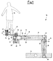
- FIG. 1 a sectional view is displayed of a support means for model fastening models according to the present finding, generally indicated with 10.
- the support means for model fastening 10 is essentially constituted by a carrier means 11, on which an arm 12 is installed, which, at one of its ends, is further provided with a support element 13 for supporting a model 14.
- the carrier means 11 is vertical
- the arm 12 is horizontal.
- Said carrier means 11 is consituted by a base plate 15, which, by means of a clamp 16, can be fastened onto a whatever supporting top 17, as displayed, e.g., in Figure 2.
- a base plate 15 Onto the base plate 15, by means of a first pin 18, an upright 19 is constrained at one of its ends (i.e., at its lower end), also bearing, at its second end (i.e., its upper end) 20, a first part 21 of the whole arm 12.
- the latter is axially constrained to said upright 19 by means of a second pin 22, which can be clamped by means of a side clamping element 23, as a so-said first grub screw housed inside a hollow provided in a portion of the side surface of the upright 19.
- the presence of the side clamping means 23 makes it possible a pivoted fastening with adjustable friction to be realized.
- the arm 12 is freely rotatable around the upright 19 which is integral with the base plate 15.
- the arm 12, i.e., its first arm part 21, extends as an enblock piece from the upper side of the upright 19, which, in its turn, is axially constrained by means of a friction pivoted fastening onto the base plate 15, and is freely rotatable.
- a second part 24 of said arm 12 is axially aligned with the first part 21 of said arm and it too is freely rotatable relatively to it.
- said first and second arm parts, 21 and 24, respectively, are mutually constrained by means of an adjustable-friction pivoted fastening means 25.
- a grub screw is provided which can be engaged and tightened inside the side surface of the first part 21 of the arm 12, and makes it possible the engagement friction between both parts of said arm 12, to be adjusted.
- the support element 13 is axially constrained by means of a second pivoted fastening means 26 onto the second part 24 of the arm 12. In this way, the support element 13 can be positioned around said pivoted fastening means 26, according to any desired mutual orientation.
- Said support element 13 is furthermore provided with elements 27 for stably positioning the model 14.
- the support element 13 is constituted by a support plate 28.
- Said support plate 28 is constrained by means of the pivoted fastening means 26 onto a screw-threaded pin 29 and consequently to the second part 24 of the arm 12.
- the screw-threaded pin 29 is furthermore fastened, by means of a second grub screw 30, to a knob 31, thus realizing a adjustable-friction pivoted fastening means onto the second part 24 of the arm 12.
- the operator can freely rotate and orientate at willing said support element 13 around the above said pivoted fastening means 29, by acting on the knob 31.
- a hollow 32 provided inside the second part 24 of the arm 12, inside which the friction pivoted fastening means 25 is housed, can be closed by means of an external, freely removable, element 33, acting as a cap.
- the elements 27 for stabling positioning the model 14 are preferably, and for exemplifying purposes, made with a cylindrical shape. However, an element having a cross section with a rectangular shape, or with any other shape, is not excluded. Said stable positioning elements 27 are fastened onto the support plate 28 by means of a pivoted fastening means 34 which make them integral with said plate 28.
- the stable positioning element 27 is furthermore provided with a bore 35 inside the interior of which a stud 36, the model 14 is equipped with, is slid. Said stud 36 is then fastened inside the interior of the bore 35 by means of a third grub screw 37, acting as a locking element. The so fastened model 14 results hence to be integrally fastened to said element 27, and consequently to the support plate 28.
- the model After fastening the support elements 27, the model can be turned, as shown, e.g., in Figure 3, i.e., the previously disclosed parts of the model support means which allow such a movement can be rotated, with no risk that the model may fall down from the support means 10.
- said support means for model fastening 10 is displayed with a first embodiment of the support plate 28, in which said support plate 28 is given the shape of a circle sector.
- a slot having a circle arc shape 38 is provided, which acts as a guide in order to position said stable positioning elements 27, according to any desired configuration.
- said stable positioning elements 27 are moved along the slot 38 to any desired position, i.e., in that position which is aligned with and corresponding to, the studs 36 extending from the model 14.
- the stable positioning elements 27 can slide inside the interior of the slot 38 and can be locked at a whatever point thereof.
- a second embodiment of the support plate is shown as indicated with 28'.
- the stable positioning element 27 can be only placed at one point on the surface of the plate, i.e., in a fixed, previously selected, position.
- pivoted fastening means 18, 22, 25, 26, 29 and 34 can be realized, e.g., as displayed in the exemplifying figures, by means of socket head screws.
- further embodiments realized by means of simple screw-threaded pins where necessary, and having contoured actuation heads, such as knobs, like the one shown in 31, are not excluded.
- the friction pivoted fastening means essentially comprise a screw acting as a pivot between both support portions to be mutually linked, and a clamping grub screw destined to lock said pivot screw in a more or less tightened position thereof.
- the friction force can be regulated and calibrated according to the requirements of mutual engagements of the implied parts.
- mutual trueing elements are provided, which are positioned at the mutually facing ends of both coupled parts.
- a structure is provided between the first part 21 and the second part 24 of the arm 12, thanks to the presence of mutual trueing elements 39 provided at the mutually facing ends of both parts 21, 24; in such an example, these elements are constituted by a recessed portion of the one part which enters a complementary seat provided on the other part.
- One of the most important advantages offered by the support means for model fastening according to the present invention is that, once that the model is fastened onto said support cylinders, as disclosed hereinabove, the operator no longer needs touching it until his work is finished.
- every part of the model can be accessed by acting on the various pivoted fastening means in order to rotate the model 14, i.e., its support plate 28, 28', around a horizontal axis, a vertical axis, or according to a direction which is the resultant of both movements.
- Another, very important, advantage is also that the operator has his hands completely free during the painting or finishing work.
- a further, not less important, advantage derives from the possibility of rotating individual parts of the above said support means.
- the model, integrally fastened onto the support plate will be always available in any desired orientations and angles, thus allowing the operator to easily reach also the most difficult-to-paint points. And all the above without any risks that the model, once turned, may fall down from its support means.
Landscapes
- Footwear And Its Accessory, Manufacturing Method And Apparatuses (AREA)
- Toys (AREA)
Applications Claiming Priority (2)
| Application Number | Priority Date | Filing Date | Title |
|---|---|---|---|
| ITMI930010A IT1271909B (it) | 1993-01-08 | 1993-01-08 | Suola composta per calzature e suo procedimento di fabbricazione |
| ITMI930010 | 1993-01-08 |
Publications (1)
| Publication Number | Publication Date |
|---|---|
| EP0605919A1 true EP0605919A1 (fr) | 1994-07-13 |
Family
ID=11364591
Family Applications (1)
| Application Number | Title | Priority Date | Filing Date |
|---|---|---|---|
| EP93203610A Withdrawn EP0605919A1 (fr) | 1993-01-08 | 1993-12-21 | Dispositif de support pour la fixation d'un modèle |
Country Status (2)
| Country | Link |
|---|---|
| EP (1) | EP0605919A1 (fr) |
| IT (1) | IT1271909B (fr) |
Cited By (2)
| Publication number | Priority date | Publication date | Assignee | Title |
|---|---|---|---|---|
| FR2878468A1 (fr) * | 2004-11-30 | 2006-06-02 | Loik Lamalle | Dispositif articule pour chevalet de peintre |
| EP2412445A1 (fr) * | 2010-07-29 | 2012-02-01 | Matthias Koch | Châssis destiné à recevoir des pièces usinées devant être revêtues |
Citations (4)
| Publication number | Priority date | Publication date | Assignee | Title |
|---|---|---|---|---|
| DE629175C (de) * | 1936-04-24 | Ernst Ziehl Dr | Vorrichtung zum Festhalten von Zinnfiguren waehrend ihrer Bemalung | |
| DE8628425U1 (de) * | 1986-10-24 | 1987-02-12 | Freier, Martin, 5100 Aachen | 3-Achsen-Werkstück-Positionierer |
| FR2602449A1 (fr) * | 1986-08-07 | 1988-02-12 | Ochsner Ernst | Dispositif a installer en position fixe pour saisir des pieces |
| EP0410833A1 (fr) * | 1989-07-27 | 1991-01-30 | Renault Automation | Procédé et dispositif de manutention robotisé |
-
1993
- 1993-01-08 IT ITMI930010A patent/IT1271909B/it active IP Right Grant
- 1993-12-21 EP EP93203610A patent/EP0605919A1/fr not_active Withdrawn
Patent Citations (4)
| Publication number | Priority date | Publication date | Assignee | Title |
|---|---|---|---|---|
| DE629175C (de) * | 1936-04-24 | Ernst Ziehl Dr | Vorrichtung zum Festhalten von Zinnfiguren waehrend ihrer Bemalung | |
| FR2602449A1 (fr) * | 1986-08-07 | 1988-02-12 | Ochsner Ernst | Dispositif a installer en position fixe pour saisir des pieces |
| DE8628425U1 (de) * | 1986-10-24 | 1987-02-12 | Freier, Martin, 5100 Aachen | 3-Achsen-Werkstück-Positionierer |
| EP0410833A1 (fr) * | 1989-07-27 | 1991-01-30 | Renault Automation | Procédé et dispositif de manutention robotisé |
Cited By (3)
| Publication number | Priority date | Publication date | Assignee | Title |
|---|---|---|---|---|
| FR2878468A1 (fr) * | 2004-11-30 | 2006-06-02 | Loik Lamalle | Dispositif articule pour chevalet de peintre |
| EP2412445A1 (fr) * | 2010-07-29 | 2012-02-01 | Matthias Koch | Châssis destiné à recevoir des pièces usinées devant être revêtues |
| WO2012013357A1 (fr) * | 2010-07-29 | 2012-02-02 | Matthias Koch | Bâti pour recevoir des pièces à revêtir |
Also Published As
| Publication number | Publication date |
|---|---|
| ITMI930010A1 (it) | 1994-07-08 |
| IT1271909B (it) | 1997-06-10 |
| ITMI930010A0 (it) | 1993-01-08 |
Similar Documents
| Publication | Publication Date | Title |
|---|---|---|
| US4590695A (en) | Adjustable quilting frame | |
| US4145006A (en) | Work piece mounting stand | |
| GB2115479A (en) | Supporting assembly | |
| US4253648A (en) | Adjustable off-set spring loaded clamp and stand | |
| EP0286959A2 (fr) | Support réglable | |
| US5385327A (en) | Universal document support monitor stand | |
| US4717109A (en) | Adjustable traveling mahl and magnetic support for mounting artist's canvases | |
| US4572595A (en) | Rotational shelf apparatus | |
| DE3600613C2 (fr) | ||
| US5195707A (en) | Optic positioning device | |
| DE29800747U1 (de) | Armauflage für Computerbediener | |
| US4123127A (en) | Artist's kit | |
| US4175343A (en) | Needlework stand | |
| US3964402A (en) | Portable stage | |
| US4141523A (en) | Projector having an adjustable height | |
| US5383636A (en) | Bracket system for mounting a cable splicing tool to a pedestal | |
| US3104762A (en) | Adjustable paint brush holder | |
| US3948136A (en) | Mitre box with improved indexing means | |
| GB2359513A (en) | Workpiece support device with angularly adjustable support member | |
| EP0064028A3 (fr) | Pupitre combiné à un appareil à écran | |
| US5984244A (en) | Mouse support | |
| US20070266938A1 (en) | Device for Holding Components | |
| US6036779A (en) | Brackets to hold spoilers for painting | |
| US6375138B1 (en) | Stanchion clamp apparatus | |
| US6604737B1 (en) | Utility workstation |
Legal Events
| Date | Code | Title | Description |
|---|---|---|---|
| PUAI | Public reference made under article 153(3) epc to a published international application that has entered the european phase |
Free format text: ORIGINAL CODE: 0009012 |
|
| AK | Designated contracting states |
Kind code of ref document: A1 Designated state(s): AT BE CH DE DK ES FR GB GR IE IT LI NL |
|
| 17P | Request for examination filed |
Effective date: 19941230 |
|
| 17Q | First examination report despatched |
Effective date: 19960517 |
|
| 18D | Application deemed to be withdrawn |
Effective date: 19961128 |