EP0605950A1 - Améliorations dans un dispositif de fabrication de tuyaux de béton - Google Patents
Améliorations dans un dispositif de fabrication de tuyaux de béton Download PDFInfo
- Publication number
- EP0605950A1 EP0605950A1 EP93309200A EP93309200A EP0605950A1 EP 0605950 A1 EP0605950 A1 EP 0605950A1 EP 93309200 A EP93309200 A EP 93309200A EP 93309200 A EP93309200 A EP 93309200A EP 0605950 A1 EP0605950 A1 EP 0605950A1
- Authority
- EP
- European Patent Office
- Prior art keywords
- assembly
- concrete
- vibrator
- concrete forming
- forming assembly
- Prior art date
- Legal status (The legal status is an assumption and is not a legal conclusion. Google has not performed a legal analysis and makes no representation as to the accuracy of the status listed.)
- Granted
Links
Images


Classifications
-
- B—PERFORMING OPERATIONS; TRANSPORTING
- B06—GENERATING OR TRANSMITTING MECHANICAL VIBRATIONS IN GENERAL
- B06B—METHODS OR APPARATUS FOR GENERATING OR TRANSMITTING MECHANICAL VIBRATIONS OF INFRASONIC, SONIC, OR ULTRASONIC FREQUENCY, e.g. FOR PERFORMING MECHANICAL WORK IN GENERAL
- B06B1/00—Methods or apparatus for generating mechanical vibrations of infrasonic, sonic, or ultrasonic frequency
- B06B1/18—Methods or apparatus for generating mechanical vibrations of infrasonic, sonic, or ultrasonic frequency wherein the vibrator is actuated by pressure fluid
- B06B1/186—Methods or apparatus for generating mechanical vibrations of infrasonic, sonic, or ultrasonic frequency wherein the vibrator is actuated by pressure fluid operating with rotary unbalanced masses
-
- B—PERFORMING OPERATIONS; TRANSPORTING
- B28—WORKING CEMENT, CLAY, OR STONE
- B28B—SHAPING CLAY OR OTHER CERAMIC COMPOSITIONS; SHAPING SLAG; SHAPING MIXTURES CONTAINING CEMENTITIOUS MATERIAL, e.g. PLASTER
- B28B21/00—Methods or machines specially adapted for the production of tubular articles
- B28B21/02—Methods or machines specially adapted for the production of tubular articles by casting into moulds
- B28B21/10—Methods or machines specially adapted for the production of tubular articles by casting into moulds using compacting means
- B28B21/22—Methods or machines specially adapted for the production of tubular articles by casting into moulds using compacting means using rotatable mould or core parts
- B28B21/24—Methods or machines specially adapted for the production of tubular articles by casting into moulds using compacting means using rotatable mould or core parts using compacting heads, rollers, or the like
- B28B21/28—Methods or machines specially adapted for the production of tubular articles by casting into moulds using compacting means using rotatable mould or core parts using compacting heads, rollers, or the like combined with vibration means
Definitions
- This invention relates generally to improvements in concrete pipe fabrication. More particularly, this invention relates to an improved combination packerhead and vibrating core assembly in a concrete pipe making machine and a high speed method of forming concrete pipe. The invention thus provides the benefits of a counter rotating packerhead with a vibrating core in one system.
- Counter rotating packerheads for concrete pipe making machines are known in the art. Counter rotating packerheads with a vibrator disposed below the packerhead are also known in the art. However, no design taught by the prior art effectively combines the benefits provided by counter rotating packerhead technology with vibrator technology to provide a concrete pipe making machine that produces high quality pipe at high production rates.
- U.S. Patent No. 4,540,539 discloses a counter rotating packerhead with an upper roller assembly and a lower long bottom assembly disposed below the upper roller assembly for use in dry cast pipe production. This radial distribution process is also known as concrete forming.
- the upper roller assembly acts to initially distribute the dry cast concrete radially outward through a wire reinforcing cage against a concrete pipe mold. After the dry cast concrete is initially pressed against the cage and mold by the upper rotating roller assembly, the lower rotating longbottom assembly further presses the dry cast concrete against the cage and mold.
- U.S. Patent No. 4,957,424 discloses a counter rotating packerhead with a vibrator disposed below the packerhead. This patent is said to represent an improvement over methods of concrete pipe making that include a counter rotating packerhead only or a vibrating core only.
- the earlier methods that implemented vibrating cores only produced a high density concrete pipe because the vibration process is very effective in consolidating or densifying dry cast concrete.
- the vibration process is quite slow and has its own disadvantages. Further, this machine is only capable of producing one pipe at a time.
- Concrete pipe making methods that employ vibrators only are subject to slumping problems unless carefully contracted.
- the voids and other distortions are primarily caused by the volume reduction of the concrete after the vibration. Vibration causes dry cast concrete to densify which results in a reduction in volume. The reduction in volume will result in void spaces around the form work, especially at or near the wire reinforcing cages.
- the vibrator shown in Figures 4 and 13 are hydraulic vibrators. Because of the size of hydraulic vibrators generally, the vibrator must be disposed substantially below the lower roller assembly of the counter rotating packerhead. This placement further compromises the potential effectiveness of the general concept of combining a counter rotating packerhead with a vibrator. Ideally, strong vibrating forces should vibrate the concrete immediately after or concurrently with the application of the radially outward forming forces exerted by the counter rotating packerhead. By combining the action of the counter rotating packerhead with an immediate vibrating action, the entire pipe making process could be shortened. However, as disclosed in U.S. Patent No. 4,957,424, the actions of the counter rotating packerhead and the vibrator are separate and distinct from one another due to the inherent structure of the hydraulic vibrator, thereby prolonging the pipe making process.
- Figure 9 represents an attempt to provide a compact drive system for a counter rotating packerhead to be disposed between the vibrator and counter rotating packerhead. Simply put, the two drive gears and multiple bearings disclosed in Figure 9 are subject to the high amplitude vibrations provided by the vibrator disposed immediately beneath the motor. The result is a mechanically unreliable machine. Neither Figures 4 or 13 teach or suggest an isolation section to isolate the packerhead and its associated drive means shown in Figure 9 from the vibrator.
- Sti another problem associated with the prior art is the general lack of attempts to increase the rate of pipe making construction.
- the present invention contributes to this need in the art by providing a counter rotating packerhead assembly where the vibrator and counter rotating packerhead are disposed adjacent to one another for faster pipe making processes.
- the present invention also discloses a pipe making machine with multiple cores and multiple forms so the machine makes at least two pipes of equal or different sizes at once, thereby increasing pipe productivity.
- the present invention makes a significant contribution to the art of concrete pipe making by providing a system and method for producing reinforced concrete pipe with a combined counter rotating packerhead and vibrator assembly which enables high speed concrete pipe making without sacrificing pipe quality.
- the present invention also discloses an apparatus for combining multiple pipe making assemblies on one turntable to produce multiple pipes of equal or different sizes at once in an automated process.
- the present invention also discloses an improved vibratorfor use in concrete pipe making equipment.
- the improved combined counter rotating packerhead and vibrator assembly is based upon an improved counter rotating packerhead/vibrator/drive means configuration and an improved vibrator design.
- the counter rotating packerhead preferably consists of an upper concrete forming assembly disposed immediately above a lower concrete forming assembly.
- the forming assemblies are preferably upper and lower roller assemblies but it will be understood that a long bottom assembly may be substituted for either roller assembly (or rollers) and still fall within the spirit and scope of the present invention.
- the upper and lower concrete forming assemblies rotate in opposite directions to eliminate cage twist.
- the upper and lower concrete forming assemblies are driven by a common drive system. Power is supplied to both upper and lower concrete forming assemblies via a coaxial drive shaft system.
- the coaxial drive shaft extends downward from the forming assemblies through the vibrating core.
- a short isolation section to protect moving parts of the lower concrete forming assembly from the vibrator and to allow the vibrating core to move independently to further densify the concrete while under pressure from the concrete forming assemblies and therefore with greater vibration efficiency.
- the vibrator Disposed immediately below the isolation section is the vibrator.
- the vibrator is of an annular configuration allowing the coaxial drive shaft system to pass directly through it. Because of the unique annular configuration of the vibrator, the means for driving the upper and lower concrete forming assemblies of the counter rotating packerhead can be mounted at a remote location below the vibrator and below the vibrator core.
- the preferred vibrator is of the pneumatic type having an orbiting roller or rollers. Provision can also be made to add replaceable wearing surface material to any or all of the rollers or roller surfaces.
- the annularly configured vibrator includes an annular top plate and an annular bottom plate.
- An annular vibrator body connects the outer peripheries of the top and bottom plates while an annular vibrator shaft connects the inner peripheries of the top and bottom plates.
- the annular space bound by the top and bottom plates, the body and the shaft, houses an outer cylindrical roller, an inner cylindrical roller and an impeller vane. The vane is disposed within the inner cylindrical roller. It should be understood however that it is feasible in some cases to run with a single rotating cylinder.
- the annular shaft contains a conduit that establishes fluid communication between a pressurized fluid source and the vane. Pressurized fluid contacts the vane through the vibrator shaft and the vane induces an eccentric circular rotation of the inner and outer cylindrical rollers, thereby causing the annular vibrator body to vibrate.
- the vibrator body transmits vibrations to the core skin to which the vibrator is rigidly mounted which in turn transmits the vibrations to the dry cast concrete. This results in denser, higher quality concrete pipe.
- the preferred pressurized fluid is air.
- the above-noted configuration provides a superior concrete pipe making machine for the following reasons.
- the upper and lower concrete forming assemblies apply radially outward forces to the concrete which results in pressure being applied to the concrete in the outward, upward and downward directions.
- the downward pressure exerted by the upper concrete forming assembly is counteracted by the upward pressure exerted by the lower concrete forming assembly. This action results in dense, pre-packed concrete.
- the downward forces exerted by the lower concrete forming assembly are immediately combined with and counteracted by the vibrating action of the vibrator which, in accordance with the present invention, is disposed immediately below the lower concrete forming assembly on the lower side of the isolation section.
- the concrete is not vibrated until it has been pre-packed by the upper and lower concrete forming assemblies and therefore the additional densifying action attributable to the vibration does not result in significant volume reduction orcon- crete-slumping that leads to voids in the finished product.
- a typical material used in the manufacture of concrete pipes is zero or very low slump concrete.
- the improved combination counter rotating packerhead and vibrating core assembly of the present invention also lends itself to an improved method of manufacturing concrete pipe.
- the assembly enters a lower end of the reinforcing wire cage located within a concrete pipe mold.
- Computer controlled equipment feeds dry cast concrete down through an upper end of the mold and cage.
- the upper concrete forming assembly (preferably an upper roller assembly) applies a radially outward force to the concrete, thereby pressing the concrete outward through the cage and against the mold as well as upward and downward.
- the lower concrete forming assembly (either a lower roller assembly or a lower longbottom assembly) applies a second radially outward force against the dry cast concrete further condensing and pressing the concrete through the cage and against the mold.
- the concrete pushed upward by the lower concrete forming assembly collides with and is pre-packed with the concrete that is being pushed downward by the upper concrete forming assembly.
- the vibrating core then vibrates the dry cast concrete almost si multaneously with the downward pressure action of the lower roller or longbottom assembly further consolidating and densifying the dry cast concrete.
- the combination of the counter rotating packerhead immediately followed by strong vibrational forces produces concrete pipe with higher densities and produces the denser pipe at rates equal to or faster than previously known concrete pipe making methods.
- the combination provided by the present invention also alleviates the problems of voids in the concrete and concrete-slumping which have been previously attributable to the densification (consolidation) action of the vibrator.
- Another object of the present invention is to provide an improved counter rotating packerhead and vibrating core assembly with two counter rotating roller assemblies for manufacturing concrete pipe.
- Yet another object of the present invention is to provide an improved combination counter rotating packerhead and vibrating core assembly with one rotating roller assembly and a counter rotating longbottom assembly or, alternatively, two counter rotating longbottom assemblies for manufacturing concrete pipe.
- Another object of the present invention is to provide an improved annularly configured vibrator for use in concrete manufacturing machines.
- Still another object of the present invention is to provide an improved pneumatic vibrator that enables roller assembly drive shafts or other means of power transmission to bypass it, thereby enabling the vibrator to be disposed immediately below the counter rotating packerhead.
- Yet another object is to provide an improved pneumatic vibrator that enables roller assembly drive shafts or other means of transmission to by-pass it whereby the vibrator may be centrally located with respect to the mold and pipe in formation, all of which results in uniform vibration. It will be understood that if the vibratory forces are not evenly and uniformly imparted to the concrete, the compaction pattern will be uneven and the goal of equal concentricity of vibrations induced in the concrete will not be attained.
- Another object of the present invention is to provide an improved concrete fabricating machine that automatically manufactures two pipes at once.
- Still another object of the present invention is to provide a faster method of making quality concrete pipe than known before.
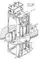
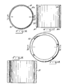
- a concrete pipe making machine is indicated generally at 10.
- the machine includes dual feed conveyors 11, 12, dual pipe molds 13, 14 and dual cores 15,16. After two pipes are fabricated in molds 13, 14, the turntable 17 is rotated 90, 180 or 270 degrees so that two additional molds 18, 19 are placed under the platform 22 and the process is begun again. The entire process is automated and controlled via the automation control panel 23.
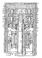
- FIG. 2 the action of a combination counter rotating packerhead and vibrator assembly is indicated generally at 40.
- the assembly is illustrated inside a mold, indicated at 13. Concrete 41 is supplied downward from a conveyor, such as 11 (see Figure 1).
- the mold 13 is equipped with a reinforcing cage 42.
- each upper roller 45 is rotatably mounted to the base plate 46 by a bolt 47.
- the base plate 46 is fixedly attached to the inner drive shaft 48 by the head nut 63.
- the upper base plate 46 is locked to the inner drive shaft 48 by a hub 62 having an integral key 60 which meshes with the spline 61 on the upper end of shaft 48.
- the inner drive shaft is turned in the direction of the arrow 52 by a drive means or motor located beneath the lift platform 28 (not shown).
- the outer drive shaft 49 is rotated in the direction of the arrow 53, which is in a direction opposite to the inner drive shaft 48, by a drive means located beneath left platform 28 (see Figure 1) to provide the counter rotating action.
- the lower roller assembly indicated generally at 37, includes rollers 54 which are rotatably attached to a base plate 55 by bolts 56.
- the base plate 55 is connected to the outer drive shaft 49 by attachment to the circular sleeve 57 which is in turn welded to the upper end of outer drive shaft 49.
- the base plate 55 is mounted to the sleeve 57 by bolt 58.
- the upper roller assembly includes the upper rollers 45 and the lower rollers 54 which are all mounted to the posts or bolts 47, 56 respectively with a plurality of bearings, shown generally at 64.
- Each base plate 46, 55 is equipped with an outer abrasion resistant member, shown generally at 59.
- Another aspect of the invention resides in the isolation of the roller assemblies 36 and 37 from the vibrator 65. This is primarily accomplished by the isolation section 68 that includes a bearing 66 mounted on rubber bushings 67 to mechanically isolate the roller assemblies 36, 37 from the vibrator 65. As best seen in Figure 2, it will be noted that the vibrator 65, despite being isolated from the lower rollers 54, is sti II disposed essentially immediately below the lower rollers 54.
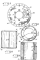
- the vibrator 65 consists of an annular top plate 72 and an annular bottom plate 73 which are connected one to the other by an annular vibrator body 74, see also Figure 15, at the outer peripheries of the top plate 72 and bottom plate 73 via a plurality of bolts, shown generally at 76. Further, the annular top plate 72 and the annular bottom plate 73 are connected at the inner peripheries thereof by a vibrator shaft 75, see also Figure 10, and the bolts 77.
- the annular space bound by the top plate 72, the bottom plate 73, the body 74 and the shaft 75 contains a vane, indicated generally at 78 (see Figures 4-7), an inner roller 79 and an outer roller 82.
- the vibrator 65 shown in Figure 2 is a pneumatic vibrator that is driven by air or another suitable fluid supplied through the hose 83 which is connected to a pressurized fluid supply (not shown). Air enters through the hose 83, through the conduit 84 in shaft 75, and through the small drilled holes 85 in the vibrator shaft 75. After passing through the small drilled holes 85, the air engages the vane 78 which in turn drives the inner roller 79 and the outer roller 82 in a rotating fashion indicated by the arrow 86.
- Durable O-rings or other sealing means 80 may be disposed in the grooves 80a disposed in the upper and lower ends of the inner roller 79 to inhibit the leakage of air as air and the vane 78 engage the inner roller 79.
- the O-ring 80, quad-ring 80 or other sealing means 80 should be comprised of a durable material such as a phenolic resin or other suitable gasket material that is durable.
- the rotation indicated at 86 imparts vibration to the vibrator body 74 which is imparted to the core skin 87 through the brackets shown generally at 88.
- the upper half-bracket 88a is mounted to the vibrator body 74 while the lower half-bracket 88b is mounted to the inside of the core skin 87.
- the upper and lower bracket halves are connected by a plurality of bolts 89. It will be emphasized that the vibrator 65 is mechanically isolated from the upper and lower roller assemblies 36, 37 (or the upper and lower concrete forming assemblies 36, 37).
- the combination counter rotating packerhead and vibrator assembly 40 first applies radially outward, upward and downward forces on the concrete 41 by the action of the upper rollers 45 (or upper concrete forming assembly 36) as indicated by arrows 36a, 36b, 36c respectively as the upper rollers 45 rotate in the direction of the arrow 52.
- the action of the upper rollers 45 pushes the concrete 41 through the cage 42 and against the mold 13.
- the cage 42 is simultaneously urged or twisted in the direction of arrow 52 due to the mass, velocity and direction of movement of the concrete.
- the lower rollers 54 (or lower concrete forming assembly 37) impart additional radially outward, upward or downward forces on the concrete 41 as indicated by arrows 37a, 37b and 37c respectively further pressing it through the cage 42 and against the mold 13.
- the mass, velocity and direction of movement of the concrete exerts a twisting force on the cage in the direction of the arrow 53 which substantially or entirely counteracts the twist imparted to the cage by the upper roller assembly 36 as indicated by the arrow 52.
- the downward forces 36c of the upper rollers 45 counteract the upward forces 37b of the lower rollers 54 thereby effectively pre-packing the concrete prior to vibration.
- the concrete 41 in general and especially the concrete being pushed in the direction of arrow 37c is contemporaneously and immediately subjected to vibrations from the vibrator 65 through the core skin 87.
- an important benefit of the present invention is the location of the vibrator 65 almost directly beneath the lower rollers 54 so as to i m-part vibratory forces to the dry cast concrete 41 immediately after it has been displaced radially outward through the cage 42 and against the mold 13 by the upper rollers 45 and lower rollers 54.
- This preferred arrangement is accomplished by providing a vibrator that is driven by a motive fluid which requires a space only sufficient to accommodate a motive fluid power supply conduit.
- the solid and hollow drive shafts 48, 49 pass through the annulus of the vibrator 65.
- FIGs 4-7 illustrate of the construction and operation of the vibrator 65 in greater detail.
- the top plate 72, the bottom plate 73, the body 74 (see also Figure 15) and the shaft 75 (see also Figure 10) define an annular area that contains the vane 78, the inner roller 79 and the outer roller 82.
- Air enters from the air hose 83 (shown in Figure 2), through the inlet 84a into the conduit 84 drilled within the wall of the shaft 75. Air then passes through the small drilled holes, shown generally at 85, and engages the vane 78.
- the action of the air against the vane 78 causes rotation of the inner roller 79 and outer roller 82 in a circular fashion indicated by the arrow 86 shown in Figure 2.
- half-bracket 88a connects the vibrator 65 to the core 87 (see Figure 2) the vibratory impulses generated by vibrator 65 are imparted to the freshly pre-packed concrete disposed between the mold 13 and the core skin 87.
- FIGs 5 and 6 are detailed illustrations of the vane 78.
- the vane 78 is preferably made of phenolic bonded canvas with a series of slots 90 disposed therein. Air enters through the entrance 90a of the slots and causes the vane 78 to engage the inner roller 79 (not shown in Figure 5; see Figure 4).
- Figure 6 is an illustration of the relative thickness of the vane 78 and the slots 90.
- FIG 8 is a side view of the vibrator shaft 75.
- the small drilled holes 85 allow for the pressurized fluid to pass through and engage the vane 78 (see Figure 4).
- the shoulder 81 of the shaft 75 engages the inside corners of extensions 96 of the top plate 72 and the bottom plate 73 (see Figures 4, 10, 12 and 14).
- the vibrator shaft 75 includes a series of bolt holes 92 for attachment to the top plate 72 and the bottom plate 73.
- the conduit 84 allows pressurized fluid from the pressurized fluid reservoir (not shown) to enter the shaft body 75 and pass through the small drilled holes 85 to engage the vane 78.
- FIGS 11 and 12 it will be noted that the slots 93 allow for the escape of pressurized fluid that enters the vibrator 65 from the pressurized fluid reservoir.
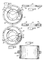
- Figures 16 and 17 illustrate the inner ring 79, sealing means 80 and groove 90.
- Figures 18 and 19 illustrate the outer ring 82.
- the vibrational action of the vibrator 65, and specifically the action of the rings 79 and 82, is best understood upon viewing Figures 20A through 20D. Air enters through the small drilled holes 85 and engages the vane 78, driving it outwardly until the left end of the vane 78, as viewed in Figure 5, engages the inner peripheries of inner ring 79.
- FIGS 21A through 21 D illustrate this circular vibrating motion in a vibrator having smaller inner ring 79a and outer ring 82a.
- FIG 22 is an illustration of an alternative embodiment.
- the counter rotating packerhead assembly indicated generally at 140, includes an upper set of rollers indicated generally at 145 and a lower longbottom assembly indicated generally at 154 in lieu of a lower set of rollers 54 (compare with Figure 2).
- the longbottom assembly 154 is mounted to the longbottom support plate 155 which in turn is connected to the outer drive shaft by bolts 158.
- the wear resistant segments 159 can be replaced upon removing the screw 162 and nut 162a.
- Abrasion resistant wear bands 159a help prevent dry cast concrete from entering the inner workings of the counter rotating packerhead 140.
- the vibrating core shown at 187 is analogous to that shown at 87 in Figure 2.
- an improved packerhead and vibrator assembly for improved quality pipe which can be made at a rate much faster than the rate at which vibrated pipe is currently made.
- the unique an- nularvibrator allows the vibrator to be disposed closer to the packerhead than known heretofore.
- the drive means for the assembly is now disposed safely below the vibrator and is protected from the vibrations imparted to the core by the vibrator.
- the disclosed design is mechanically more reliable and produces quality pipe faster than designs previously available.
Landscapes
- Engineering & Computer Science (AREA)
- Mechanical Engineering (AREA)
- Manufacturing & Machinery (AREA)
- Chemical & Material Sciences (AREA)
- Ceramic Engineering (AREA)
- Manufacturing Of Tubular Articles Or Embedded Moulded Articles (AREA)
- Press-Shaping Or Shaping Using Conveyers (AREA)
- Rigid Pipes And Flexible Pipes (AREA)
- On-Site Construction Work That Accompanies The Preparation And Application Of Concrete (AREA)
Applications Claiming Priority (2)
| Application Number | Priority Date | Filing Date | Title |
|---|---|---|---|
| US980398 | 1992-11-23 | ||
| US07/980,398 US5364578A (en) | 1992-11-23 | 1992-11-23 | Combination counter rotating packerhead and vibrator assembly and method of operation thereof |
Publications (2)
| Publication Number | Publication Date |
|---|---|
| EP0605950A1 true EP0605950A1 (fr) | 1994-07-13 |
| EP0605950B1 EP0605950B1 (fr) | 1999-04-28 |
Family
ID=25527532
Family Applications (1)
| Application Number | Title | Priority Date | Filing Date |
|---|---|---|---|
| EP93309200A Expired - Lifetime EP0605950B1 (fr) | 1992-11-23 | 1993-11-18 | Améliorations dans un dispositif de fabrication de tuyaux de béton |
Country Status (10)
| Country | Link |
|---|---|
| US (1) | US5364578A (fr) |
| EP (1) | EP0605950B1 (fr) |
| JP (1) | JP2879300B2 (fr) |
| AT (1) | ATE179357T1 (fr) |
| AU (1) | AU5184793A (fr) |
| CA (1) | CA2103437C (fr) |
| DE (1) | DE69324664T2 (fr) |
| DK (1) | DK0605950T3 (fr) |
| ES (1) | ES2133367T3 (fr) |
| NZ (1) | NZ250210A (fr) |
Cited By (2)
| Publication number | Priority date | Publication date | Assignee | Title |
|---|---|---|---|---|
| EP0673685A1 (fr) * | 1994-03-04 | 1995-09-27 | International Pipe Machinery Corporation | Vibrateur pneumatique |
| CN102310480A (zh) * | 2011-09-26 | 2012-01-11 | 江苏邦威机械制造有限公司 | 径向挤压制管机 |
Families Citing this family (8)
| Publication number | Priority date | Publication date | Assignee | Title |
|---|---|---|---|---|
| DE4422891C1 (de) * | 1994-06-30 | 1995-03-02 | Wensauer Betonwerk Gmbh | Verdichtungskopf einer Fertigungsmaschine für Stahlbetonrohre |
| US7125239B2 (en) | 2003-04-07 | 2006-10-24 | International Pipe Machinery Corporation | Concrete pipe manufacturing machinery and methods |
| US20060169868A1 (en) * | 2005-01-31 | 2006-08-03 | Precast Concepts, Llc | Precast concrete meter pit and method and apparatus for making same |
| US8282869B2 (en) * | 2005-01-31 | 2012-10-09 | Precast Concepts, Llc | Method for making precast concrete meter pit |
| CN111152356B (zh) * | 2020-01-17 | 2021-05-18 | 重庆华西易通建设股份有限公司 | 一种预制混凝土件及其制造装置 |
| CN112060301B (zh) * | 2020-09-10 | 2021-09-17 | 阜阳市华顺水泥制品有限公司 | 一种水泥涵管成型后干燥定型设备 |
| US20230167649A1 (en) * | 2021-05-20 | 2023-06-01 | Besser Company | Bellpacker vibration assembly |
| CN114474354B (zh) * | 2021-12-16 | 2026-01-02 | 扬州市华光双瑞实业有限公司 | 一种内模升降式芯模振动制管机 |
Citations (6)
| Publication number | Priority date | Publication date | Assignee | Title |
|---|---|---|---|---|
| FR1418422A (fr) * | 1964-11-25 | 1965-11-19 | Vibrateur rotatif et systèmes à oscillations synchrones | |
| FR2261410A1 (en) * | 1974-02-19 | 1975-09-12 | Netter Jean | Pneumatically driven rotary vibration generating motor - is bolted to appliance being vibrated, through cylinder end plates |
| GB2010400A (en) * | 1977-12-15 | 1979-06-27 | Halilovic Esref | Vibrators |
| EP0388347A2 (fr) * | 1989-03-13 | 1990-09-19 | International Pipe Machinery Corporation | Machine pour la fabrication de tuyaux en ciment |
| US5080571A (en) * | 1990-02-28 | 1992-01-14 | International Pipe Machinery Corporation | Packerhead assembly |
| DE4227196A1 (de) * | 1992-08-17 | 1993-04-22 | Zueblin Ag | Verfahren zur herstellung von betonrohren und vorrichtung zur durchfuehrung des verfahrens |
Family Cites Families (14)
| Publication number | Priority date | Publication date | Assignee | Title |
|---|---|---|---|---|
| US3096556A (en) * | 1961-06-23 | 1963-07-09 | Randell C Woods | Concrete pipe forming apparatus |
| US3276091A (en) * | 1964-04-20 | 1966-10-04 | Charles B Pausch | Roller head for cement pipe forming |
| US3752626A (en) * | 1969-10-17 | 1973-08-14 | Viropac Inc | Vibratory core for concrete pipe making machine |
| US3733163A (en) * | 1970-09-01 | 1973-05-15 | Concrete Pipe Mach Co | Wear surface for concrete pipe machine long bottoms |
| US4041118A (en) * | 1975-02-05 | 1977-08-09 | Atlantic Pipe Corporation | Method and apparatus for making concrete pipe |
| US4238177A (en) * | 1978-04-24 | 1980-12-09 | Crile Eugene E | Molding machine with vibration isolation |
| US4340553A (en) * | 1978-12-29 | 1982-07-20 | Hydrotile Machinery Company | Machine and method for making concrete product |
| US4253814A (en) * | 1979-01-29 | 1981-03-03 | Hydrotile Canada Limited | Packerhead and core control system |
| US4540539A (en) * | 1982-12-21 | 1985-09-10 | International Pipe Machinery Corp. | Method and apparatus for production of concrete pipe by the packerhead method |
| US4690631A (en) * | 1986-03-06 | 1987-09-01 | Hydrotile Machinery Company | Packerhead with elastic rollers |
| US4756861A (en) * | 1986-12-31 | 1988-07-12 | Schultz Ronald C | Vibratory concrete pipe forming apparatus and method |
| US4957474A (en) | 1988-11-14 | 1990-09-18 | Tractiontec Corporation | Traction drive transmission system |
| US5147196A (en) * | 1989-11-13 | 1992-09-15 | International Pipe Machinery Corporation | Machine for making concrete pipes |
| US5167967A (en) * | 1989-11-13 | 1992-12-01 | International Pipe Machinery Corporation | Machine for making concrete pipes |
-
1992
- 1992-11-23 US US07/980,398 patent/US5364578A/en not_active Expired - Lifetime
-
1993
- 1993-11-16 NZ NZ250210A patent/NZ250210A/en not_active IP Right Cessation
- 1993-11-18 EP EP93309200A patent/EP0605950B1/fr not_active Expired - Lifetime
- 1993-11-18 ES ES93309200T patent/ES2133367T3/es not_active Expired - Lifetime
- 1993-11-18 DE DE69324664T patent/DE69324664T2/de not_active Expired - Fee Related
- 1993-11-18 CA CA002103437A patent/CA2103437C/fr not_active Expired - Fee Related
- 1993-11-18 AT AT93309200T patent/ATE179357T1/de not_active IP Right Cessation
- 1993-11-18 DK DK93309200T patent/DK0605950T3/da active
- 1993-11-22 AU AU51847/93A patent/AU5184793A/en not_active Abandoned
- 1993-11-24 JP JP5317399A patent/JP2879300B2/ja not_active Expired - Fee Related
Patent Citations (6)
| Publication number | Priority date | Publication date | Assignee | Title |
|---|---|---|---|---|
| FR1418422A (fr) * | 1964-11-25 | 1965-11-19 | Vibrateur rotatif et systèmes à oscillations synchrones | |
| FR2261410A1 (en) * | 1974-02-19 | 1975-09-12 | Netter Jean | Pneumatically driven rotary vibration generating motor - is bolted to appliance being vibrated, through cylinder end plates |
| GB2010400A (en) * | 1977-12-15 | 1979-06-27 | Halilovic Esref | Vibrators |
| EP0388347A2 (fr) * | 1989-03-13 | 1990-09-19 | International Pipe Machinery Corporation | Machine pour la fabrication de tuyaux en ciment |
| US5080571A (en) * | 1990-02-28 | 1992-01-14 | International Pipe Machinery Corporation | Packerhead assembly |
| DE4227196A1 (de) * | 1992-08-17 | 1993-04-22 | Zueblin Ag | Verfahren zur herstellung von betonrohren und vorrichtung zur durchfuehrung des verfahrens |
Cited By (3)
| Publication number | Priority date | Publication date | Assignee | Title |
|---|---|---|---|---|
| EP0673685A1 (fr) * | 1994-03-04 | 1995-09-27 | International Pipe Machinery Corporation | Vibrateur pneumatique |
| CN102310480A (zh) * | 2011-09-26 | 2012-01-11 | 江苏邦威机械制造有限公司 | 径向挤压制管机 |
| CN102310480B (zh) * | 2011-09-26 | 2016-06-15 | 江苏邦威机械制造有限公司 | 径向挤压制管机 |
Also Published As
| Publication number | Publication date |
|---|---|
| EP0605950B1 (fr) | 1999-04-28 |
| DE69324664T2 (de) | 1999-12-02 |
| AU5184793A (en) | 1994-06-02 |
| DK0605950T3 (da) | 1999-10-25 |
| ES2133367T3 (es) | 1999-09-16 |
| DE69324664D1 (de) | 1999-06-02 |
| ATE179357T1 (de) | 1999-05-15 |
| JP2879300B2 (ja) | 1999-04-05 |
| US5364578A (en) | 1994-11-15 |
| CA2103437A1 (fr) | 1994-05-24 |
| JPH07329047A (ja) | 1995-12-19 |
| NZ250210A (en) | 1995-05-26 |
| CA2103437C (fr) | 1997-09-30 |
Similar Documents
| Publication | Publication Date | Title |
|---|---|---|
| EP0605950B1 (fr) | Améliorations dans un dispositif de fabrication de tuyaux de béton | |
| US2356852A (en) | Method and apparatus for making concrete pipe | |
| EP0388347B1 (fr) | Machine pour la fabrication de tuyaux en ciment | |
| US2470068A (en) | Device for molding and coating pipes and like articles | |
| CN207841708U (zh) | 一种混凝土管桩离心成型机 | |
| AU624401B2 (en) | Concrete block molding machine having continuously driven vibrating shaft mechanism which can be programmably vibrated and method of programmably vibrating such machines | |
| US2605533A (en) | Apparatus for applying a continuous layer of cementitious material to the surface of a vertical structure | |
| US4600548A (en) | Method of forming the primary core of a prestressed concrete pipe | |
| KR100253949B1 (ko) | 개선된 진동기 및 그 진동기를 구비한 기계 | |
| US3945782A (en) | Concrete pipes | |
| SE421280B (sv) | Forfarande och anordning for framstellning av betongror genom pafyllning och komprimering av betongmassa i en upprettstaende form | |
| AU678861B2 (en) | An improved combination counter rotating packerhead and vibrator assembly and method of operating thereof | |
| US3741669A (en) | Ground compacting apparatus | |
| US3012298A (en) | Vibrating structure for concrete pipe forming machine | |
| US5456590A (en) | Counter-rotating compaction head for manufacturing concrete pipes | |
| US2712679A (en) | Means for forming argillaceous pipe | |
| USRE33101E (en) | Method of forming the primary core of a prestressed concrete pipe | |
| US2560426A (en) | Machine for forming concrete pipes | |
| US3642413A (en) | Method and apparatus for making hollow bodies of concrete or the like | |
| RU2368721C1 (ru) | Вибрационный ленточный рабочий орган | |
| CN207465504U (zh) | 一种制管机挤压成型头 | |
| SU1043014A1 (ru) | Способ формовани трубчатых изделий | |
| JP2849628B2 (ja) | コンクリート管の製造方法とその装置 | |
| US1528518A (en) | Process and apparatus for making concrete structures centrifugally | |
| US2374087A (en) | Apparatus and process for making pipes |
Legal Events
| Date | Code | Title | Description |
|---|---|---|---|
| PUAI | Public reference made under article 153(3) epc to a published international application that has entered the european phase |
Free format text: ORIGINAL CODE: 0009012 |
|
| AK | Designated contracting states |
Kind code of ref document: A1 Designated state(s): AT CH DE DK ES FR GB IT LI NL SE |
|
| 17P | Request for examination filed |
Effective date: 19940926 |
|
| K1C1 | Correction of patent application (title page) published |
Effective date: 19940713 |
|
| 17Q | First examination report despatched |
Effective date: 19960607 |
|
| GRAG | Despatch of communication of intention to grant |
Free format text: ORIGINAL CODE: EPIDOS AGRA |
|
| GRAG | Despatch of communication of intention to grant |
Free format text: ORIGINAL CODE: EPIDOS AGRA |
|
| GRAH | Despatch of communication of intention to grant a patent |
Free format text: ORIGINAL CODE: EPIDOS IGRA |
|
| GRAH | Despatch of communication of intention to grant a patent |
Free format text: ORIGINAL CODE: EPIDOS IGRA |
|
| GRAH | Despatch of communication of intention to grant a patent |
Free format text: ORIGINAL CODE: EPIDOS IGRA |
|
| GRAA | (expected) grant |
Free format text: ORIGINAL CODE: 0009210 |
|
| AK | Designated contracting states |
Kind code of ref document: B1 Designated state(s): AT CH DE DK ES FR GB IT LI NL SE |
|
| REF | Corresponds to: |
Ref document number: 179357 Country of ref document: AT Date of ref document: 19990515 Kind code of ref document: T |
|
| REG | Reference to a national code |
Ref country code: CH Ref legal event code: EP |
|
| REF | Corresponds to: |
Ref document number: 69324664 Country of ref document: DE Date of ref document: 19990602 |
|
| ET | Fr: translation filed | ||
| REG | Reference to a national code |
Ref country code: CH Ref legal event code: NV Representative=s name: DR. R.C. SALGO EUROPEAN PATENT ATTORNEY |
|
| REG | Reference to a national code |
Ref country code: ES Ref legal event code: FG2A Ref document number: 2133367 Country of ref document: ES Kind code of ref document: T3 |
|
| REG | Reference to a national code |
Ref country code: DK Ref legal event code: T3 |
|
| PLBE | No opposition filed within time limit |
Free format text: ORIGINAL CODE: 0009261 |
|
| 26N | No opposition filed | ||
| REG | Reference to a national code |
Ref country code: GB Ref legal event code: IF02 |
|
| PGFP | Annual fee paid to national office [announced via postgrant information from national office to epo] |
Ref country code: DK Payment date: 20031104 Year of fee payment: 11 |
|
| PGFP | Annual fee paid to national office [announced via postgrant information from national office to epo] |
Ref country code: ES Payment date: 20031105 Year of fee payment: 11 |
|
| PGFP | Annual fee paid to national office [announced via postgrant information from national office to epo] |
Ref country code: GB Payment date: 20031113 Year of fee payment: 11 |
|
| PGFP | Annual fee paid to national office [announced via postgrant information from national office to epo] |
Ref country code: FR Payment date: 20031114 Year of fee payment: 11 |
|
| PGFP | Annual fee paid to national office [announced via postgrant information from national office to epo] |
Ref country code: NL Payment date: 20031118 Year of fee payment: 11 |
|
| PGFP | Annual fee paid to national office [announced via postgrant information from national office to epo] |
Ref country code: AT Payment date: 20031124 Year of fee payment: 11 |
|
| PGFP | Annual fee paid to national office [announced via postgrant information from national office to epo] |
Ref country code: SE Payment date: 20031127 Year of fee payment: 11 |
|
| PGFP | Annual fee paid to national office [announced via postgrant information from national office to epo] |
Ref country code: DE Payment date: 20040130 Year of fee payment: 11 |
|
| PGFP | Annual fee paid to national office [announced via postgrant information from national office to epo] |
Ref country code: CH Payment date: 20040202 Year of fee payment: 11 |
|
| PG25 | Lapsed in a contracting state [announced via postgrant information from national office to epo] |
Ref country code: GB Free format text: LAPSE BECAUSE OF NON-PAYMENT OF DUE FEES Effective date: 20041118 Ref country code: AT Free format text: LAPSE BECAUSE OF NON-PAYMENT OF DUE FEES Effective date: 20041118 |
|
| PG25 | Lapsed in a contracting state [announced via postgrant information from national office to epo] |
Ref country code: SE Free format text: LAPSE BECAUSE OF NON-PAYMENT OF DUE FEES Effective date: 20041119 Ref country code: ES Free format text: LAPSE BECAUSE OF NON-PAYMENT OF DUE FEES Effective date: 20041119 |
|
| PG25 | Lapsed in a contracting state [announced via postgrant information from national office to epo] |
Ref country code: LI Free format text: LAPSE BECAUSE OF NON-PAYMENT OF DUE FEES Effective date: 20041130 Ref country code: DK Free format text: LAPSE BECAUSE OF NON-PAYMENT OF DUE FEES Effective date: 20041130 Ref country code: CH Free format text: LAPSE BECAUSE OF NON-PAYMENT OF DUE FEES Effective date: 20041130 |
|
| PG25 | Lapsed in a contracting state [announced via postgrant information from national office to epo] |
Ref country code: NL Free format text: LAPSE BECAUSE OF NON-PAYMENT OF DUE FEES Effective date: 20050601 Ref country code: DE Free format text: LAPSE BECAUSE OF NON-PAYMENT OF DUE FEES Effective date: 20050601 |
|
| REG | Reference to a national code |
Ref country code: DK Ref legal event code: EBP |
|
| EUG | Se: european patent has lapsed | ||
| GBPC | Gb: european patent ceased through non-payment of renewal fee |
Effective date: 20041118 |
|
| REG | Reference to a national code |
Ref country code: CH Ref legal event code: PL |
|
| PG25 | Lapsed in a contracting state [announced via postgrant information from national office to epo] |
Ref country code: FR Free format text: LAPSE BECAUSE OF NON-PAYMENT OF DUE FEES Effective date: 20050729 |
|
| NLV4 | Nl: lapsed or anulled due to non-payment of the annual fee |
Effective date: 20050601 |
|
| REG | Reference to a national code |
Ref country code: FR Ref legal event code: ST |
|
| PG25 | Lapsed in a contracting state [announced via postgrant information from national office to epo] |
Ref country code: IT Free format text: LAPSE BECAUSE OF NON-PAYMENT OF DUE FEES Effective date: 20051118 |
|
| REG | Reference to a national code |
Ref country code: ES Ref legal event code: FD2A Effective date: 20041119 |