EP0606032A1 - Chariot d'avance et machine de brochage comportant un tel chariot - Google Patents
Chariot d'avance et machine de brochage comportant un tel chariot Download PDFInfo
- Publication number
- EP0606032A1 EP0606032A1 EP93403139A EP93403139A EP0606032A1 EP 0606032 A1 EP0606032 A1 EP 0606032A1 EP 93403139 A EP93403139 A EP 93403139A EP 93403139 A EP93403139 A EP 93403139A EP 0606032 A1 EP0606032 A1 EP 0606032A1
- Authority
- EP
- European Patent Office
- Prior art keywords
- plate
- tool holder
- tool
- traction
- drilling
- Prior art date
- Legal status (The legal status is an assumption and is not a legal conclusion. Google has not performed a legal analysis and makes no representation as to the accuracy of the status listed.)
- Granted
Links
- 238000003754 machining Methods 0.000 claims abstract description 6
- 238000005553 drilling Methods 0.000 claims description 28
- 125000006850 spacer group Chemical group 0.000 claims description 5
- 230000008878 coupling Effects 0.000 claims description 4
- 238000010168 coupling process Methods 0.000 claims description 4
- 238000005859 coupling reaction Methods 0.000 claims description 4
- 230000000284 resting effect Effects 0.000 claims 1
- 238000005452 bending Methods 0.000 description 4
- 230000000295 complement effect Effects 0.000 description 3
- 230000008901 benefit Effects 0.000 description 2
- 238000006073 displacement reaction Methods 0.000 description 2
- 238000012544 monitoring process Methods 0.000 description 2
- 238000010521 absorption reaction Methods 0.000 description 1
- 230000009471 action Effects 0.000 description 1
- 230000006866 deterioration Effects 0.000 description 1
- 230000002706 hydrostatic effect Effects 0.000 description 1
- 238000004519 manufacturing process Methods 0.000 description 1
- 230000007246 mechanism Effects 0.000 description 1
- 230000009467 reduction Effects 0.000 description 1
Images

Classifications
-
- B—PERFORMING OPERATIONS; TRANSPORTING
- B23—MACHINE TOOLS; METAL-WORKING NOT OTHERWISE PROVIDED FOR
- B23D—PLANING; SLOTTING; SHEARING; BROACHING; SAWING; FILING; SCRAPING; LIKE OPERATIONS FOR WORKING METAL BY REMOVING MATERIAL, NOT OTHERWISE PROVIDED FOR
- B23D37/00—Broaching machines or broaching devices
- B23D37/02—Broaching machines with horizontally-arranged working tools
- B23D37/04—Broaching machines with horizontally-arranged working tools for broaching inner surfaces
-
- B—PERFORMING OPERATIONS; TRANSPORTING
- B23—MACHINE TOOLS; METAL-WORKING NOT OTHERWISE PROVIDED FOR
- B23Q—DETAILS, COMPONENTS, OR ACCESSORIES FOR MACHINE TOOLS, e.g. ARRANGEMENTS FOR COPYING OR CONTROLLING; MACHINE TOOLS IN GENERAL CHARACTERISED BY THE CONSTRUCTION OF PARTICULAR DETAILS OR COMPONENTS; COMBINATIONS OR ASSOCIATIONS OF METAL-WORKING MACHINES, NOT DIRECTED TO A PARTICULAR RESULT
- B23Q1/00—Members which are comprised in the general build-up of a form of machine, particularly relatively large fixed members
- B23Q1/25—Movable or adjustable work or tool supports
- B23Q1/44—Movable or adjustable work or tool supports using particular mechanisms
- B23Q1/56—Movable or adjustable work or tool supports using particular mechanisms with sliding pairs only, the sliding pairs being the first two elements of the mechanism
- B23Q1/60—Movable or adjustable work or tool supports using particular mechanisms with sliding pairs only, the sliding pairs being the first two elements of the mechanism two sliding pairs only, the sliding pairs being the first two elements of the mechanism
- B23Q1/62—Movable or adjustable work or tool supports using particular mechanisms with sliding pairs only, the sliding pairs being the first two elements of the mechanism two sliding pairs only, the sliding pairs being the first two elements of the mechanism with perpendicular axes, e.g. cross-slides
- B23Q1/621—Movable or adjustable work or tool supports using particular mechanisms with sliding pairs only, the sliding pairs being the first two elements of the mechanism two sliding pairs only, the sliding pairs being the first two elements of the mechanism with perpendicular axes, e.g. cross-slides a single sliding pair followed perpendicularly by a single sliding pair
-
- B—PERFORMING OPERATIONS; TRANSPORTING
- B23—MACHINE TOOLS; METAL-WORKING NOT OTHERWISE PROVIDED FOR
- B23Q—DETAILS, COMPONENTS, OR ACCESSORIES FOR MACHINE TOOLS, e.g. ARRANGEMENTS FOR COPYING OR CONTROLLING; MACHINE TOOLS IN GENERAL CHARACTERISED BY THE CONSTRUCTION OF PARTICULAR DETAILS OR COMPONENTS; COMBINATIONS OR ASSOCIATIONS OF METAL-WORKING MACHINES, NOT DIRECTED TO A PARTICULAR RESULT
- B23Q17/00—Arrangements for observing, indicating or measuring on machine tools
- B23Q17/09—Arrangements for observing, indicating or measuring on machine tools for indicating or measuring cutting pressure or for determining cutting-tool condition, e.g. cutting ability, load on tool
Definitions
- the present invention relates to a feed carriage for a broaching machine and, more particularly, to such a carriage supporting a tool holder designed to couple to the driver of a broaching tool inserted in a pre-drilling. formed in a part to be drilled with a hole of predetermined dimensions, the advance carriage being movable so as to drive the tool holder and the tool in a predetermined direction to pull the tool through the pre-drilling and form thus said hole.
- Broaching machines equipped with such advance carriages are well known in the art.
- the broaching tool having to be pulled through the pre-drilling to enlarge the latter by pulling out chips up to the dimensions of the hole to be machined, it is understood that it is necessary to center the tool and the tool holder, presented on either side of the pre-drilling, on the axis thereof.
- the workpiece When the workpiece is small, it automatically centers itself on the broaching tool, or spindle, during the machining of the hole.
- the part is not mobile, for example because of its size and / or its significant weight, it is necessary to be able to center the spindle manually or automatically in the pre-drilling if one wishes to avoid an off-center of the final hole compared to pre-drilling.
- Multispindle machines are also known, capable of drilling several holes simultaneously in the same part. It happens that the manufacturing tolerances of such parts are more severe with regard to the diameter of the holes to be drilled than with regard to the inter-axes of these holes. In this situation, it is important that each of the spindles can be self-centered on the pre-drilling provided for it so as to ensure the machining of perfectly calibrated holes, even if the centers of these would be subject to tolerances less strict. This is the case, for example, of plates serving as spacers for bundles of tubes in large capacity heat exchangers. Correct centering of the pins in the Corresponding pre-drilling also has the advantage of avoiding the application of bending stresses to the broaching tools and therefore of altering their cutting capacities and possibly their service life.
- the object of the present invention is therefore to produce a feed carriage for a broaching machine designed so as to allow the self-centering of a broaching tool in a pre-drilling formed in a broaching piece.
- the present invention also aims to produce such a feed carriage usable in a multispindle machine.
- the advance carriage for a broaching machine, supporting a tool holder designed to mate with the driver for a broaching tool inserted into a pre-drilling formed in a workpiece to be drilled with a hole of predetermined dimensions, the advance carriage being movable so as to drive the tool holder and the tool in a predetermined direction to pull the tool through the pre-drilled hole.
- the advance carriage comprises means for supporting the tool holder with two degrees of freedom perpendicular to the predetermined direction, so as to allow self-centering of the tool along the axis of the pre-drilling, for machining the hole.
- said support means comprise a plate for mounting the tool holder on a plate of the trolley intended to develop a traction force on the tool and the tool holder, the latter being mounted movable on the plate along an axis perpendicular to its own while the plate is mounted mobile on the traction plate along an axis perpendicular to these two axes, so as to establish between the tool holder and the plate a mechanical coupling of the type "Oldham seal".
- a ring is mounted on the tool holder to support the latter sliding along an axis parallel to the predetermined direction of traction.
- the tool holder can "follow" the tool when it is centered in the pre-drilling, as soon as the plate applies traction to them.
- the axes of the tool and of the tool holder then being perfectly centered on that of the pre-drilling, the hole to be machined is also perfectly centered on the pre-drilling, even if the latter would be somewhat off-center with respect to at its nominal position.
- the coaxiality of the axes of the tool and of the pre-drilling with respect to that of the tool holder along which the tensile force applied to the broaching tool is exercised ensures that the tool does not undergo any bending or bending force likely to tire it and therefore reduce its useful life.
- the advance carriage shown in FIG. 1 comprises a tool holder 1 passing through a bore 2 of a plate 3.
- the tool holder receives a stop piece 4 being able to slide on its outer surface, this part being adjacent to a ball joint 5 bearing on an enlarged part of the part 4, the ball joint being stopped by a nut 6 fixed to the right end of the tool holder.
- a force sensor 7 is clamped between the enlarged part of the part 4 and a support ring 8 mounted on this part so as to project from the left end 9 thereof, as far as the plate 3 .
- the latter comprises means for fixing the driver of a broaching tool 10, or pin, also partially shown in this figure.
- These means conventionally comprise a ring 11 slidably mounted on the tool holder and fingers 12 movably mounted in radial holes in the tool holder. The latter is pierced with an axial bore 13 suitable for additionally receiving a driver 14 forming part of the tool 10.
- This driver has a drive surface 15 on which the fingers 12 engage when they are pushed towards the axis of the tool holder by the ring 11 (see the lower half-section of the left end of the tool holder) so as to couple the tool 10 and the tool holder 1 in translation to the right when the plate 3 is drawn in the direction of arrow F.
- the tool holder is mounted on the plate 3 so as to have two degrees of freedom perpendicular to its axis, in the bore 2 of the plate.
- the assembly is such that the axis of the tool holder is free to move parallel to itself to center on a pre-drilling (not shown) provided in a workpiece, while this part is crossed by a part of the broaching tool 10, the driver 14 of which is fixed to the tool holder 1 by the means 11, 12.
- Such a capacity finds its usefulness for example in the application mentioned above for the pinout of a tube support plate for large heat exchanger capacity.
- a plate can be provided with several thousand pre-drilled holes, a certain tolerance having to be allowed with regard to the value of the inter-axes of these pre-drilled holes, for example of the order of a millimeter, for holes to be broached at a diameter of the order of 10 mm from pre-drilled holes with smaller diameters.
- the tool holder can move transversely under the action of the forces applied to the tool by the pre-drilled part, when a tensile force begins to be exerted on the plate 3 to pass the spindle through the pre-drilling.
- the possible transverse movement of the axis of the tool holder must therefore be able to absorb any variation in the center-axes between holes. In the hypothesis considered above where this variation is of the order of a millimeter, the authorized transverse displacement of the axis of the tool holder must be of the same order, therefore small but not nonexistent.
- a mounting plate 16 in the form of a disc is installed between it and the plate 3 (see FIG. 2), the tool holder 1 being movable relative to the following plate. a diameter perpendicular to the plane of Figure 1 while the plate is movable relative to the plate 3 along an axis perpendicular to that of the tool holder, in the plane of Figure 1, so as to establish between the tool holder and the plate a mechanical coupling of the type of that of the so-called "Oldham” joint conventionally established between two butted shafts, parallel and offset, to transmit to one a printed rotation to the other.
- the plate 16 is mounted against a ring 17 slid over the middle part of the tool holder, to which this ring is secured by a spline connection 18 allowing the tool holder to slide along the axis of the ring, perpendicular to the plate 3
- Two studs 19,19 'diametrically opposite and projecting from the ring 17 slide in two complementary grooves 20,20', respectively, cut at the ends of a diameter in the plate 16, as is more apparent on the central part of FIG. 2.
- the tool holder 1 movable from the right to the left and from left to right with respect to the mounting plate 18, within the limit offered by the movement of the studs 19,19 'in the grooves 20,20' respectively.
- the mounting plate 16 is mounted vertically movable on a base 21 fixed by means (not shown) on the plate 3. To do this, the plate 16 is cut from two other grooves 22, 22 'diametrically opposite on a diameter of the plate 16 perpendicular to that on which the grooves 20,20' are centered, the latter cooperating with sliding with complementary studs 23,23 'respectively, fixed to the base 21 by bolts 24,24 ' respectively.
- the tool holder 1 can move in all directions of the plane of Figure 2, with a maximum clearance limited by the game j2 (see figure 1) established between the base 21 and an enlarged part of the ring 17 against which the plate 16 slides.
- Return springs (not shown) center the tool holder in the bore 2 of the plate, when the tool holder is not subjected to forces other than its weight.
- the forces developed by these springs are established at a level such that, as soon as a tool attached to the tool holder is in contact with the edges of a pre-drilling while the plate 3 begins to pull on the tool holder to pull the tool through this pre-drilling, the forces developed at the tool / pre-drilling interface outweigh the forces developed by the return springs and tend to drive the tool holder in a position centered on the pre - drilling by balancing the transverse forces exerted at this interface.
- a stop for example with balls, generally marked 25 in FIG. 1.
- This comprises two ball cages 26, 26 ′ separated by a race 27 blocked on the base 21 by a screw ring 28.
- the ball stop is itself axially locked on the ring 17 by a nut 29.
- the tool must be prevented from tilting relative to the direction of traction, during the centering and machining phases.
- the sliding mounting of the tool holder 1 in the ring 17 prevents, according to the present invention, such a tilting.
- This assembly allows, during the absorption of play j1, the two parts to move relative to each other while maintaining their orientation.
- the nut 29 makes it possible to prestress the ball stop 25 and guarantees a perfectly radial movement of the tool and the tool holder, which remains parallel to itself during the self-centering phase.
- the axis of the spindle remains parallel to the axis of the pre-drilling which eliminates the application of any bending constraint on the spindle and therefore the additional fatigue and wear which could result therefrom.
- the ball stop 25 does not support axial overloads. Indeed, the tensile force applied to the plate 3 is transmitted directly to the tool holder 1 via the support ring 8 after removal of the axial play j1.
- the force sensor 7 can be of any known type, for example piezoelectric or with strain gauge. It provides a signal to electronic means for monitoring the amplitude of the axial force collected by the tool holder and therefore by the tool. If this effort exceeds one predetermined value, these means can command a stop or a reduction in the tensile force exerted on the spindle, in order to avoid deterioration of the broaching machine. According to the invention, the variations in the effort collected are continuously monitored, so that the imminence of an overshoot can be detected and corrective measures taken accordingly.
- the advance carriage according to the invention can be adapted to a multi-spindle machine, by assembling several plates and associated tool holders using transverse tie rods 30,31,32,33.
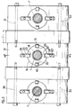
- three plates 3.3 ', 3''of tool holder supports 1.1', 1 '' respectively are assembled with the interposition of spacers 34.35 of thickness l calculated for establish predetermined nominal center-axes between the spindles carried by the tool holders.
- the invention is not limited to the embodiment described and shown which has been given only by way of example.
- the ball bearing could be replaced by hydrostatic, aerostatic bearings or by any other means allowing a radial displacement of the tool holder with a minimum of friction.
- the spacers 34, 35 of the multispindle carriage shown in FIG. 2 could be replaced by a platen support in the form of a "comb", this comb being shaped to arrange the tool holders with respect to each other with between - predetermined nominal axes.
- We could also replace the mechanism described above, of the "Oldham seal" type combined with the axial sliding of the tool holder in the ring 17, any other known means allowing a translation of the tool holder with conservation of its orientation.
Landscapes
- Engineering & Computer Science (AREA)
- Mechanical Engineering (AREA)
- Drilling And Boring (AREA)
- Machine Tool Units (AREA)
Abstract
Description
- La présente invention est relative à un chariot d'avance pour machine de brochage et, plus particulièrement, à un tel chariot supportant un porte-outil conçu pour s'accoupler à l'entraîneur d'un outil de brochage introduit dans un pré-perçage formé dans une pièce à percer d'un trou de dimensions prédéterminées, le chariot d'avance étant mobile de manière à entraîner le porte-outil et l'outil dans une direction prédéterminée pour tirer l'outil à travers le pré-perçage et former ainsi ledit trou.
- Des machines de brochage équipées de tels chariots d'avance sont bien connues dans la technique. L'outil de brochage devant être tiré à travers le pré-perçage pour agrandir celui-ci par arrachage de copeaux jusqu'aux dimensions du trou à usiner, on comprend qu'il est nécessaire de centrer l'outil et le porte-outil, présentés de part et d'autre du pré-perçage, sur l'axe de celui-ci. Quand la pièce à usiner est de petites dimensions, celle-ci s'autocentre automatiquement sur l'outil de brochage, ou broche, pendant l'usinage du trou. Par contre, si la pièce n'est pas mobile, par exemple du fait de son encombrement et/ou de son poids importants, il faut pouvoir centrer manuellement ou automatiquement la broche dans le pré-perçage si l'on veut éviter un décentrement du trou final par rapport au pré-perçage.
- On connaît aussi des machines de multibrochage, capables de percer plusieurs trous simultanément dans une même pièce. Il arrive que les tolérances de fabrication de telles pièces soient plus sévères en ce qui concerne le diamètre des trous à percer qu'en ce qui concerne les entre-axes de ces trous. Dans cette situation, il importe que chacune des broches puissent s'autocentrer sur le pré-perçage prévu pour elle de manière à assurer l'usinage de trous parfaitement calibrés, quand bien même les entre-axes de ceux-ci seraient soumis à des tolérances moins strictes. C'est le cas par exemple de plaques servant d'entretoises pour des faisceaux de tubes dans des échangeurs thermiques de grande capacité. Un centrage correct des broches dans les pré-perçages correspondants présente en outre l'avantage d'éviter d'appliquer des contraintes de flexion aux outils de brochage et donc d'altérer leurs capacités de coupe et éventuellement leur durée de vie.
- La présente invention a donc pour but de réaliser un chariot d'avance pour machine de brochage conçu de manière à permettre l'autocentrage d'un outil de brochage dans un pré-perçage formé dans une pièce à brocher.
- La présente invention a aussi pour but de réaliser un tel chariot d'avance utilisable dans une machine de multibrochage.
- On atteint ces buts de l'invention, ainsi que d'autres qui apparaîtront à la lecture de la description qui va suivre, avec un chariot d'avance pour machine de brochage, supportant un porte-outil conçu pour s'accoupler à l'entraîneur d'un outil de brochage introduit dans un pré-perçage formé dans une pièce à percer d'un trou de dimensions prédéterminées, le chariot d'avance étant mobile de manière à entraîner le porte-outil et l'outil dans une direction prédéterminée pour tirer l'outil à travers le pré-perçage. Suivant l'invention, le chariot d'avance comprend des moyens pour supporter le porte-outil avec deux degrés de liberté perpendiculairement à la direction prédéterminée, de manière à autoriser un autocentrage de l'outil suivant l'axe du pré-perçage, pour l'usinage du trou.
- Suivant un mode de réalisation préféré du chariot selon l'invention, lesdits moyens de support comprennent un plateau de montage du porte-outil sur une platine du chariot prévue pour développer un effort de traction sur l'outil et le porte-outil, ce dernier étant monté mobile sur le plateau suivant un axe perpendiculaire au sien alors que le plateau est monté mobile sur la platine de traction suivant un axe perpendiculaire à ces deux axes, de manière à établir entre le porte-outil et la platine un couplage mécanique du type "joint d'Oldham". En outre, une bague est montée sur le porte-outil pour supporter celui-ci à coulissement suivant un axe parallèle à la direction prédéterminée de traction.
- Grâce à ce couplage et à ce montage, le porte-outil peut "suivre" l'outil quand celui-ci se centre dans le pré-perçage, dès que la platine applique une traction sur ceux-ci. Les axes de l'outil et du porte-outil étant alors parfaitement centrés sur celui du pré-perçage, le trou à usiner est lui-aussi parfaitement centré sur le pré-perçage, quand bien même celui-ci serait quelque peu décentré par rapport à sa position nominale. En outre, la coaxialité des axes de l'outil et du pré-perçage par rapport à celui du porte-outil suivant lequel s'exerce l'effort de traction appliqué à l'outil de brochage, assure que l'outil ne subit aucun effort de flexion ou de cintrage susceptible de le fatiguer et donc de diminuer sa durée de vie utile.
- D'autres caractéristiques et avantages de la présente invention apparaîtront à la lecture de la description qui va suivre et à l'examen du dessin annexé dans lequel :
- la figure 1 représente une vue partielle du chariot d'avance suivant l'invention, en coupe axiale suivant le trait de coupe I-I de la figure 2, et
- la figure 2 est une vue d'un chariot multibroche selon l'invention, prise suivant la flèche F₁ de la figure 1.
- Le chariot d'avance représenté à la figure 1 comprend un porte-outil 1 traversant un alésage 2 d'une platine 3. A son extrémité droite, du point de vue de la figure 1, le porte-outil reçoit une pièce de butée 4 pouvant glisser sur sa surface extérieure, cette pièce étant adjacente à une rotule 5 en appui sur une partie élargie de la pièce 4, la rotule étant arrêtée par un écrou 6 fixé à l'extrémité droite du porte-outil. Un capteur d'effort 7 est pincé entre la partie élargie de la pièce 4 et une bague d'appui 8 montée sur cette pièce de manière à déborder de l'extrémité gauche 9 de celle-ci, jusqu'au voisinage de la platine 3.
- Ainsi, en fonctionnement, lorsqu'un effort de traction est appliqué sur la platine 3 par des moyens (non représentés) tels qu'un vérin hydraulique, la platine s'appuie sur l'extrémité adjacente de la bague 8, après rattrapage d'un faible jeu j₁. L'effort de traction ainsi développé est transmis au porte-outil 1 par l'intermédiaire de la bague 8 alors que le capteur 7, pincé entre cette bague et la pièce 4, délivre un signal représentatif de l'amplitude de cet effort à des moyens (non représentés) de surveillance de celui-ci, pour un but que l'on expliquera plus loin.
- Comme cela apparaît sur les demi-vues en coupe axiale de l'extrémité gauche (du point de vue de la figure 1) du porte-outil 1, celui-ci comprend des moyens de fixation de l'entraîneur d'un outil de brochage 10, ou broche, également partiellement représenté à cette figure. Ces moyens comprennent classiquement une bague 11 montée coulissante sur le porte-outil et des doigts 12 montés mobiles dans des trous radiaux du porte-outil. Celui-ci est percé d'un alésage axial 13 propre à recevoir complémentairement un entraîneur 14 formant partie de l'outil 10. Cet entraîneur comporte une surface d'entraînement 15 sur laquelle les doigts 12 viennent en prise quand ils sont repoussés vers l'axe du porte-outil par la bague 11 (voir la demi-coupe inférieure de l'extrémité gauche du porte-outil) de manière à coupler l'outil 10 et le porte-outil 1 en translation vers la droite quand la platine 3 est tirée dans le sens de la flèche F.
- Suivant une caractéristique essentielle du chariot selon la présente invention, le porte-outil est monté sur la platine 3 de manière à disposer de deux degrés de liberté perpendiculairement à son axe, dans l'alésage 2 de la platine. Le montage est tel que l'axe du porte-outil est libre de se déplacer parallèlement à lui-même pour se centrer sur un pré-perçage (non représenté) prévu dans une pièce à brocher, alors que cette pièce est traversée par une partie de l'outil de brochage 10 dont l'entraîneur 14 est fixé au porte-outil 1 par les moyens 11,12.
- Une telle capacité trouve son utilité par exemple dans l'application mentionnée ci-dessus au brochage d'une plaque de support de tubes pour échangeur thermique de grande capacité. Une telle plaque peut être munie de plusieurs milliers de pré-perçages, une certaine tolérance devant être admise quant à la valeur des entre-axes de ces pré-perçages, par exemple de l'ordre du millimètre, pour des trous à brocher à un diamètre de l'ordre de 10 mm à partir de pré-perçages de diamètres inférieurs.
- Pour qu'une broche passée dans un tel pré-perçage se centre correctement sur celui-ci, il est indispensable que le porte-outil puisse se déplacer transversalement sous l'action des forces appliquées à l'outil par la pièce pré-percée, lorsqu'un effort de traction commence à être exercé sur le plateau 3 pour faire passer la broche à travers le pré-perçage. Le déplacement transversal possible de l'axe du porte-outil doit ainsi pouvoir absorber toute variation d'entre-axes entre perçages. Dans l'hypothèse envisagée plus haut où cette variation est de l'ordre du millimètre, le déplacement transversal autorisé de l'axe du porte-outil devra être du même ordre, donc faible mais pas inexistant.
- Pour obtenir un tel montage "flottant" du porte-outil, on installe entre celui-ci et la platine 3 un plateau de montage 16 en forme de disque (voir figure 2), le porte-outil 1 étant mobile par rapport au plateau suivant un diamètre perpendiculaire au plan de la figure 1 alors que le plateau est mobile par rapport à la platine 3 suivant un axe perpendiculaire à celui du porte-outil, dans le plan de la figure 1, de manière à établir entre le porte-outil et la platine un couplage mécanique du type de celui du joint dit "d'Oldham" classiquement établi entre deux arbres aboutés, parallèles et désaxés, pour transmettre à l'un une rotation imprimée à l'autre.
- Le plateau 16 est monté contre une bague 17 glissée sur la partie médiane du porte-outil, auquel cette bague est solidarisée par une liaison à cannelures 18 autorisant un glissement du porte-outil suivant l'axe de la bague, perpendiculaire à la platine 3. Deux tenons 19,19' diamétralement opposés et débordant de la bague 17 coulissent dans deux rainures complémentaires 20,20', respectivement, découpées aux extrémités d'un diamètre dans le plateau 16, comme cela est plus apparent sur la partie centrale de la figure 2. Ainsi, du point de vue de la figure 2, le porte -outil 1 est-il mobile de droite à gauche et de gauche à droite par rapport au plateau de montage 18, dans la limite offerte par le débattement des tenons 19,19' dans les rainures 20,20' respectivement.
- Sur la figure 2, il apparaît aussi que le plateau de montage 16 est monté mobile verticalement sur une base 21 fixée par des moyens (non représentés) sur la platine 3. Pour ce faire, le plateau 16 est découpé de deux autres rainures 22,22' diamétralement opposées sur un diamètre du plateau 16 perpendiculaire à celui sur lequel sont centrées les rainures 20,20', ces dernières coopérant à glissement avec des tenons complémentaires 23,23' respectivement, fixés sur la base 21 par des boulons 24,24' respectivement.
- On comprend que, grâce aux deux jeux de rainures et de tenons complémentaires décrits ci-dessus, le porte-outil 1 peut se déplacer dans toutes les directions du plan de la figure 2, avec un débattement maximum limité par le jeu j₂ (voir figure 1) établi entre la base 21 et une partie élargie de la bague 17 contre laquelle glisse le plateau 16.
- Des ressorts de rappel (non représentés) centrent le porte-outil dans l'alésage 2 de la platine, lorsque le porte-outil n'est pas soumis à des efforts autres que son poids. Les efforts développés par ces ressorts sont établis à un niveau tel que, dès qu'un outil attaché au porte-outil est en contact avec les bords d'un pré-perçage alors que la platine 3 commence à tirer sur le porte-outil pour tirer l'outil à travers ce pré-perçage, les efforts développés à l'interface outil/pré-perçage l'emportent sur les efforts développés par les ressorts de rappel et tendent à entraîner le porte-outil dans une position centrée sur le pré-perçage en équilibrant les efforts transversaux exercés à cette interface.
- La liberté de déplacement transversal du porte-outil, à partir d'une position centrale nominale définie par les ressorts de rappel, est assurée par la présence d'une butée, à billes par exemple, généralement repérée 25 à la figure 1. Celle-ci comprend deux cages à billes 26,26' séparées par un chemin de roulement 27 bloqué sur la base 21 par une bague vissante 28. La butée à billes est elle-même bloquée axialement sur la bague 17 par un écrou 29. Ainsi, grâce au montage "flottant" du porte-outil, en l'absence d'efforts développés entre un outil et une pièce à brocher, le porte-outil reste-t'il centré dans l'alésage 2, porté par la butée à billes 25 dans la base 21. Sous effort de traction, l'autocentrage de l'outil et du porte-outil s'établit sans contrainte grâce à la butée à billes 25.
- On notera qu'il faut empêcher l'outil de basculer par rapport à la direction de traction, pendant les phases de centrage et d'usinage. Le montage à coulissement du porte-outil 1 dans la bague 17 empêche, suivant la présente invention, un tel basculement. Ce montage permet, pendant l'absorption du jeu j₁, aux deux pièces de se déplacer l'une par rapport à l'autre en conservant leur orientation.
- On notera aussi que l'écrou 29 permet de précontraindre la butée à billes 25 et garantit un déplacement parfaitement radial de l'outil et du porte-outil, qui reste parallèle à lui-même pendant la phase d'autocentrage. Ainsi, l'axe de la broche reste parallèle à l'axe du pré-perçage ce qui permet de supprimer l'application de toute contrainte de cintrage sur la broche et donc les fatigues et usures supplémentaires qui pourraient en résulter pour celle-ci.
- On notera encore qu'en cours de brochage, la butée à billes 25 ne supporte pas de surefforts axiaux. En effet, l'effort de traction appliqué à la platine 3 est transmis directement au porte-outil 1 par l'intermédiaire de la bague d'appui 8 après suppression du jeu axial j₁.
- Le capteur d'effort 7 peut être de tout type connu, par exemple piézoélectrique ou à jauge de contrainte. Il fournit un signal à des moyens électroniques de surveillance de l'amplitude de l'effort axial encaissé par le porte-outil et donc par l'outil. En cas de dépassement par cet effort d'une valeur prédéterminée, ces moyens peuvent commander un arrêt ou une réduction de l'effort de traction exercé sur la broche, afin d'éviter une détérioration de la machine de brochage. Suivant l'invention, on surveille en permanence les variations de l'effort encaissé, de manière que l'imminence d'un dépassement puisse être détectée et des mesures correctrices prises en conséquence.
- Comme représenté à la figure 2, le chariot d'avance suivant l'invention peut être adapté à une machine de multibrochage, par assemblage de plusieurs platines et porte-outils associés à l'aide de tirants transversaux 30,31,32,33. Ainsi, à la figure 2, trois platines 3,3',3'' de supports de porte-outils 1,1',1'' respectivement sont-elles assemblées avec interposition d'entretoises 34,35 d'épaisseur l calculée pour établir des entre-axes nominaux prédéterminés entre les broches portées par les porte-outils.
- Bien entendu l'invention n'est pas limitée au mode de réalisation décrit et représenté qui n'a été donné qu'à titre d'exemple. Ainsi, on pourrait remplacer la butée à billes par des paliers hydrostatiques, aérostatiques ou par tout autre moyen autorisant un déplacement radial du porte-outil avec un minimum de frottement. Egalement, on pourrait remplacer les entretoises 34,35 du chariot de multibrochage représentées à la figure 2 par un support de platine en forme de "peigne", ce peigne étant conformé pour disposer les porte-outils les uns par rapport aux autres avec des entre-axes nominaux prédéterminés. On pourrait encore substituer au mécanisme décrit ci-dessus, du type "joint d'Oldham" combiné au coulissement axial du porte-outil dans la bague 17, tout autre moyen connu autorisant une translation du porte-outil avec conservation de son orientation.
Claims (11)
- Chariot d'avance pour machine de brochage, supportant un porte-outil (1) conçu pour s'accoupler à l'entraîneur d'un outil de brochage (10) introduit dans un pré-perçage formé dans une pièce à percer d'un trou de dimensions prédéterminées, le chariot d'avance étant mobile de manière à entraîner le porte-outil et l'outil dans une direction prédéterminée pour tirer l'outil à travers le pré-perçage, caractérisé en ce que le chariot d'avance comprend des moyens (16,25) pour supporter le porte-outil (1) avec deux degrés de liberté perpendiculairement à la direction prédéterminée, de manière à autoriser un autocentrage de l'outil sur l'axe du pré-perçage, pour l'usinage du trou.
- Chariot conforme à la revendication 1, caractérisé en ce que lesdits moyens de support comprennent un plateau de montage (16) du porte-outil (1) sur une platine (3) du chariot prévue pour développer un effort de traction sur l'outil (10) et le porte-outil (1), ce dernier étant monté mobile sur le plateau suivant un axe perpendiculaire au sien alors que le plateau est monté mobile sur la platine de traction (3) suivant un axe perpendiculaire à ces deux axes, de manière à établir entre le porte-outil et la platine un couplage mécanique du type "joint d'Oldham".
- Chariot conforme à la revendication 2, caractérisé en ce qu'une bague (17) est montée sur le porte-outil (1) pour supporter celui-ci à coulissement suivant un axe parallèle à la direction prédéterminée de traction.
- Chariot conforme à la revendication 3, caractérisé en ce que le plateau (16) est monté sur la bague (17), cette bague portant en outre au moins une butée (25) s'appuyant sur un chemin de roulement (27) solidaire de la platine (3) de traction et perpendiculaire à l'axe du porte-outil, un jeu (j₂) étant ménagé entre la périphérie de la butée (25) et la platine pour autoriser un déplacement du porte-outil perpendiculairement à son axe lors du centrage de l'outil dans le pré-perçage.
- Chariot conforme à la revendication 4, caractérisé en ce que le plateau de montage prend la forme d'un disque encoché de rainures (20,20' ; 22,22') aux extrémités de deux diamètres perpendiculaires, deux tenons (19,19') solidaires de la bague (17) coopérant avec les rainures d'un diamètre pour assurer un montage à coulissement du porte-outil (1) sur le plateau (16), suivant ce diamètre, et deux autres tenons (23,23') solidaires de la platine de traction (3) coopérant avec les deux autres rainures (22,22') pour assurer un montage à coulissement du plateau (16) sur la platine de traction (3).
- Chariot conforme à l'une quelconque des revendications précédentes, caractérisé en ce que le porte-outil (1) traverse la platine de traction (3) et comprend un capteur d'effort (7) monté sur la partie du porte-outil (1) qui déborde de la platine (3), du côté de celle-ci qui est opposé à celui où se trouve l'outil (10), le capteur (7) étant pincé entre des moyens (4,8) quand ceux-ci encaissent l'effort de traction exercé par la platine (3) sur le porte-outil (1).
- Chariot conforme à la revendication 6, caractérisé en ce qu'un jeu (j₁) est établi entre la platine de traction (3) et un moyen d'appui (8) en l'absence d'effort de traction.
- Chariot conforme à l'une quelconque des revendications 2 à 7, caractérisé en ce qu'il comprend des moyens de rappel du porte-outil (1) dans une position nominale de centrage sur la platine (3) de traction.
- Chariot d'avance pour machine de multibrochage, caractérisé en ce qu'il est constitué par la réunion de plusieurs chariots d'avance conforme à l'une quelconque des revendications précédentes, des moyens d'entretoise (34,35) étant interposés entre deux chariots adjacents pour régler l'entre-axe nominal de leurs porte-outils.
- Chariot conforme à la revendication 9, caractérisé en ce que lesdits moyens d'entretoise prennent la forme d'un support en forme de "peigne" conformé pour disposer les porte-outils les uns par rapport aux autres avec des entre-axes nominaux prédéterminés.
- Utilisation d'un chariot d'avance conforme à l'une quelconque des revendications 1 à 9, dans une machine de brochage ou de multibrochage.
Applications Claiming Priority (2)
| Application Number | Priority Date | Filing Date | Title |
|---|---|---|---|
| FR9300052 | 1993-01-06 | ||
| FR9300052A FR2700128B1 (fr) | 1993-01-06 | 1993-01-06 | Chariot d'avance et machine de brochage comportant un tel chariot. |
Publications (2)
| Publication Number | Publication Date |
|---|---|
| EP0606032A1 true EP0606032A1 (fr) | 1994-07-13 |
| EP0606032B1 EP0606032B1 (fr) | 1998-10-28 |
Family
ID=9442844
Family Applications (1)
| Application Number | Title | Priority Date | Filing Date |
|---|---|---|---|
| EP19930403139 Expired - Lifetime EP0606032B1 (fr) | 1993-01-06 | 1993-12-22 | Chariot d'avance et machine de brochage comportant un tel chariot |
Country Status (3)
| Country | Link |
|---|---|
| EP (1) | EP0606032B1 (fr) |
| DE (1) | DE69321818T2 (fr) |
| FR (1) | FR2700128B1 (fr) |
Cited By (1)
| Publication number | Priority date | Publication date | Assignee | Title |
|---|---|---|---|---|
| US7681300B2 (en) | 2005-06-22 | 2010-03-23 | Gm Global Technology Operations, Inc. | Method of broaching a work-piece |
Families Citing this family (1)
| Publication number | Priority date | Publication date | Assignee | Title |
|---|---|---|---|---|
| FR2802298B1 (fr) | 1999-12-14 | 2002-03-08 | Cie Du Sol | Procede de controle de diametre de colonnes realise par injection |
Citations (5)
| Publication number | Priority date | Publication date | Assignee | Title |
|---|---|---|---|---|
| GB553159A (en) * | 1942-08-13 | 1943-05-10 | British Manufacture And Res Co | Improvements in or relating to work holding devices for use on drilling and like machines |
| DE1801621A1 (de) * | 1968-10-07 | 1970-05-27 | Rausch Kg Maschf | Raeummaschine mit zwei gleichzeitig betaetigten Raeumnadeln |
| DE2312786A1 (de) * | 1973-03-15 | 1974-09-19 | Salje Ernst | Ausrichteinrichtung fuer werkzeugoder werkstuecktraeger |
| EP0036912A1 (fr) * | 1980-03-26 | 1981-10-07 | Maschinenfabrik Meyer AG. | Pince pour manipulateur |
| SU1526933A1 (ru) * | 1987-12-11 | 1989-12-07 | Предприятие П/Я А-7569 | Самоустанавливающа с опора к прот жным станкам |
-
1993
- 1993-01-06 FR FR9300052A patent/FR2700128B1/fr not_active Expired - Fee Related
- 1993-12-22 EP EP19930403139 patent/EP0606032B1/fr not_active Expired - Lifetime
- 1993-12-22 DE DE1993621818 patent/DE69321818T2/de not_active Expired - Lifetime
Patent Citations (5)
| Publication number | Priority date | Publication date | Assignee | Title |
|---|---|---|---|---|
| GB553159A (en) * | 1942-08-13 | 1943-05-10 | British Manufacture And Res Co | Improvements in or relating to work holding devices for use on drilling and like machines |
| DE1801621A1 (de) * | 1968-10-07 | 1970-05-27 | Rausch Kg Maschf | Raeummaschine mit zwei gleichzeitig betaetigten Raeumnadeln |
| DE2312786A1 (de) * | 1973-03-15 | 1974-09-19 | Salje Ernst | Ausrichteinrichtung fuer werkzeugoder werkstuecktraeger |
| EP0036912A1 (fr) * | 1980-03-26 | 1981-10-07 | Maschinenfabrik Meyer AG. | Pince pour manipulateur |
| SU1526933A1 (ru) * | 1987-12-11 | 1989-12-07 | Предприятие П/Я А-7569 | Самоустанавливающа с опора к прот жным станкам |
Non-Patent Citations (1)
| Title |
|---|
| SOVIET PATENTS ABSTRACTS Section PQ Week 9026, Derwent World Patents Index; Class P, AN 90-199870 * |
Cited By (1)
| Publication number | Priority date | Publication date | Assignee | Title |
|---|---|---|---|---|
| US7681300B2 (en) | 2005-06-22 | 2010-03-23 | Gm Global Technology Operations, Inc. | Method of broaching a work-piece |
Also Published As
| Publication number | Publication date |
|---|---|
| FR2700128B1 (fr) | 1995-03-10 |
| DE69321818T2 (de) | 1999-06-10 |
| DE69321818D1 (de) | 1998-12-03 |
| FR2700128A1 (fr) | 1994-07-08 |
| EP0606032B1 (fr) | 1998-10-28 |
Similar Documents
| Publication | Publication Date | Title |
|---|---|---|
| EP1344680B1 (fr) | Compensateur de défaut de parallélisme pour siège amovible de véhicule | |
| EP0340369B1 (fr) | Dispositif de montage d'attachements, de porte-outils et d'outils à application cône et face, notamment pour centres d'usinage et de tournage avec changeurs automatiques ou manuels d'outils à queue conique, en particulier au cône 7/24e | |
| EP2790860B1 (fr) | Procede d'usinage | |
| FR3009801A1 (fr) | Systeme de serrage | |
| FR2481625A1 (fr) | Porte-outil a mecanisme correcteur de position d'outil | |
| EP0317682A1 (fr) | Dispositif de montage à queue conique, en particulier au cône 7/24e, à application cône et face pour attachements, porte-outils et outils | |
| CA2965394C (fr) | Dispositif d'usinage vibratoire ameliore | |
| FR2490977A1 (fr) | Ensemble porte-taraud | |
| FR2560094A1 (fr) | Broche de machine-outil et porte-outil s'y adaptant | |
| EP0346231B1 (fr) | Perceuse perfectionnée, notamment pour machine programmable | |
| FR2612438A1 (fr) | Machine-outil, notamment perceuse ou taraudeuse | |
| EP0606032B1 (fr) | Chariot d'avance et machine de brochage comportant un tel chariot | |
| FR2530753A1 (fr) | Fourche de joint universel pour grandes puissances | |
| CH430346A (fr) | Appareillage pour l'assemblage d'un joint de Cardan | |
| KR101453567B1 (ko) | 공작기계의 보링 스핀들 헤드 연결장치 | |
| EP2030720A1 (fr) | Dispositif de guidage de précision dans une machine d'usinage de pièces cylindriques | |
| FR2972664A1 (fr) | Broche a serrage rapide | |
| EP1437521A1 (fr) | Dispositif de fixation d'un étrier de frein à disque sur une fusée d'essieu, notamment pour véhicule automobile | |
| EP0360947B1 (fr) | Pince destinée à porter un outil notamment un outil d'usinage | |
| WO2020228983A1 (fr) | Pedalier a plateau mobile | |
| EP3983159B1 (fr) | Outil de perçage | |
| CH685292A5 (fr) | Dispositif d'assemblage d'un porte-outil sur une tête d'alésage rotative. | |
| EP0549453A1 (fr) | Dispositif formant interface mécanique interposée entre l'extrémité d'un robot et un outil de travail du robot | |
| FR2533152A1 (fr) | Ensemble d'une machine-outil et d'un outil de coupe, outil de coupe, porte-outil, procede pour adapter une machine-outil a prendre et entrainer un porte-outil sans queue et procede pour changer de porte-outil | |
| FR2692510A1 (fr) | Ensemble d'outillage adaptable sur la broche porte-outil d'une machine. |
Legal Events
| Date | Code | Title | Description |
|---|---|---|---|
| PUAI | Public reference made under article 153(3) epc to a published international application that has entered the european phase |
Free format text: ORIGINAL CODE: 0009012 |
|
| AK | Designated contracting states |
Kind code of ref document: A1 Designated state(s): DE GB IT |
|
| 17P | Request for examination filed |
Effective date: 19950110 |
|
| 17Q | First examination report despatched |
Effective date: 19970611 |
|
| GRAG | Despatch of communication of intention to grant |
Free format text: ORIGINAL CODE: EPIDOS AGRA |
|
| GRAG | Despatch of communication of intention to grant |
Free format text: ORIGINAL CODE: EPIDOS AGRA |
|
| GRAG | Despatch of communication of intention to grant |
Free format text: ORIGINAL CODE: EPIDOS AGRA |
|
| GRAH | Despatch of communication of intention to grant a patent |
Free format text: ORIGINAL CODE: EPIDOS IGRA |
|
| GRAH | Despatch of communication of intention to grant a patent |
Free format text: ORIGINAL CODE: EPIDOS IGRA |
|
| GRAA | (expected) grant |
Free format text: ORIGINAL CODE: 0009210 |
|
| AK | Designated contracting states |
Kind code of ref document: B1 Designated state(s): DE GB IT |
|
| REF | Corresponds to: |
Ref document number: 69321818 Country of ref document: DE Date of ref document: 19981203 |
|
| GBT | Gb: translation of ep patent filed (gb section 77(6)(a)/1977) |
Effective date: 19990121 |
|
| PLBE | No opposition filed within time limit |
Free format text: ORIGINAL CODE: 0009261 |
|
| STAA | Information on the status of an ep patent application or granted ep patent |
Free format text: STATUS: NO OPPOSITION FILED WITHIN TIME LIMIT |
|
| 26N | No opposition filed | ||
| REG | Reference to a national code |
Ref country code: GB Ref legal event code: IF02 |
|
| PGFP | Annual fee paid to national office [announced via postgrant information from national office to epo] |
Ref country code: IT Payment date: 20091218 Year of fee payment: 17 Ref country code: GB Payment date: 20091218 Year of fee payment: 17 |
|
| PGFP | Annual fee paid to national office [announced via postgrant information from national office to epo] |
Ref country code: DE Payment date: 20091222 Year of fee payment: 17 |
|
| GBPC | Gb: european patent ceased through non-payment of renewal fee |
Effective date: 20101222 |
|
| REG | Reference to a national code |
Ref country code: DE Ref legal event code: R119 Ref document number: 69321818 Country of ref document: DE Effective date: 20110701 |
|
| PG25 | Lapsed in a contracting state [announced via postgrant information from national office to epo] |
Ref country code: DE Free format text: LAPSE BECAUSE OF NON-PAYMENT OF DUE FEES Effective date: 20110701 Ref country code: GB Free format text: LAPSE BECAUSE OF NON-PAYMENT OF DUE FEES Effective date: 20101222 |
|
| PG25 | Lapsed in a contracting state [announced via postgrant information from national office to epo] |
Ref country code: IT Free format text: LAPSE BECAUSE OF NON-PAYMENT OF DUE FEES Effective date: 20101222 |