EP0606068A1 - Borne de batterie - Google Patents
Borne de batterie Download PDFInfo
- Publication number
- EP0606068A1 EP0606068A1 EP94100062A EP94100062A EP0606068A1 EP 0606068 A1 EP0606068 A1 EP 0606068A1 EP 94100062 A EP94100062 A EP 94100062A EP 94100062 A EP94100062 A EP 94100062A EP 0606068 A1 EP0606068 A1 EP 0606068A1
- Authority
- EP
- European Patent Office
- Prior art keywords
- clamping members
- post
- battery
- battery terminal
- tightening tool
- Prior art date
- Legal status (The legal status is an assumption and is not a legal conclusion. Google has not performed a legal analysis and makes no representation as to the accuracy of the status listed.)
- Granted
Links
- 239000002184 metal Substances 0.000 claims abstract description 19
- 238000005452 bending Methods 0.000 claims abstract description 9
- 210000000078 claw Anatomy 0.000 claims description 7
- 238000010586 diagram Methods 0.000 description 1
- 238000004519 manufacturing process Methods 0.000 description 1
- 238000012986 modification Methods 0.000 description 1
- 230000004048 modification Effects 0.000 description 1
- 238000004080 punching Methods 0.000 description 1
Images
Classifications
-
- H—ELECTRICITY
- H01—ELECTRIC ELEMENTS
- H01R—ELECTRICALLY-CONDUCTIVE CONNECTIONS; STRUCTURAL ASSOCIATIONS OF A PLURALITY OF MUTUALLY-INSULATED ELECTRICAL CONNECTING ELEMENTS; COUPLING DEVICES; CURRENT COLLECTORS
- H01R11/00—Individual connecting elements providing two or more spaced connecting locations for conductive members which are, or may be, thereby interconnected, e.g. end pieces for wires or cables supported by the wire or cable and having means for facilitating electrical connection to some other wire, terminal, or conductive member, blocks of binding posts
- H01R11/11—End pieces or tapping pieces for wires, supported by the wire and for facilitating electrical connection to some other wire, terminal or conductive member
- H01R11/28—End pieces consisting of a ferrule or sleeve
- H01R11/281—End pieces consisting of a ferrule or sleeve for connections to batteries
- H01R11/283—Bolt, screw or threaded ferrule parallel to the battery post
Definitions
- the present invention relates to a battery terminal mounted to the post of a motor vehicle battery, and particularly to a battery terminal that is clamped using a tightening tool by tightening a bolt from above to firmly clamp the battery terminal to the battery post.
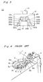
- the main terminal 3 of a conventional battery terminal of this type is made by bending a flat metal plate in two around a curve 3a at one end of the resulting main terminal 3.
- the top and bottom parts of this main terminal 3 are roughly identical in shape, and the bend imparts a certain flexibility to the terminal.
- This main terminal 3 comprises a pair of top and bottom circular post fittings 3b, each of which is flat in the horizontal direction and both of which are fit over the battery post 2.
- a pair of right and left tightening members 3c which are similarly flat in the horizontal direction, are provided contiguous to the free open ends of the circular post fittings 3b.
- the cable connector 3d is provided at the other, closed, end of the circular post fittings 3b.
- a bearing washer 5 is placed at the outside of one of the tightening members 3c, and a bolt 6 is passed through the bearing washer 5 from the outside of the other tightening member 3c.
- a nut 7 is then threaded onto the bearing washer 5 end of the bolt 6 and tightened against the bearing washer 5 to tighten the right and left tightening members 3c, thus closing the free end of the circular post fittings 3b and firmly clamping the battery terminal to the battery post 2.
- this main terminal is manufactured by bending a single metal plate and the components are fairly complex bent shapes, a thick metal plate cannot be used.
- the mechanical strength of the terminal cannot, therefore, be set high, the torque applied to the bolt 6 to tighten the tightening members 3c is not consistent, and poor contact between the battery terminal and battery post 2 can result from the instability of the bolt clamping force.
- the object of the present invention is therefore to increase the thickness of the metal plate, and thereby increase the mechanical strength, by simplifying the shape of the main terminal formed from metal plate.
- the required tightening torque can thus be made more consistent, the bolt can be tightened from above and the vertical tightening force can be converted to a horizontal force to firmly clamp the post fittings to the battery post and assure positive terminal-post contact.
- a battery terminal comprises a cable connector adapted for connection with an electrical cable; an annular post fitting formed by bending a vertically oriented metal band into an arc to form a vertically oriented cylindrical shape, and having open free ends; first and second clamping members contiguous to said open free ends of the post fitting, and formed by end portions of said vertically oriented metal band, said first and second clamping members having tapered sliding surfaces; a tightening tool comprising tapered surfaces fit over said tapered sliding surfaces; a nut positioned inside the clamping members; and a bolt passed through the tightening tool and tightened into the nut to move the tightening tool towards said first and second clamping members, thereby closing the first and second clamping members, and in turn, closing the free ends of the post fitting to firmly clamp the battery terminal to the battery post.
- Claws projecting to the inside to hold the nut, and jam walls preventing nut rotation are also provided in the right and left clamping members of the main terminal.
- Plural vertical grooves are provided in the inside wall of the main terminal post fitting to enable the free ends of the post fitting to move smoothly in the opening and closing directions.
- the main terminal is formed from thicker metal plate than that used in the conventional main terminal shown in Fig. 4.
- the typical plate thickness in a conventional terminal is 1.2 mm, 2.0 mm thick plate is used in the present invention.
- the thickness of the plate used to manufacture the main terminal can be increased in a battery terminal according to the present invention because the annular post fitting of the main terminal and the right and left clamping members contiguous to the free ends thereof are formed from a single vertically oriented plate and are shaped more simply than those of the prior art.
- the tightening torque of the bolt can also be stably applied because the mechanical strength of the main terminal can thus be increased.
- the right and left clamping members are shaped to provide sliding surfaces following the tapered surfaces of the tightening tool, the downward travel of the tightening tool caused by tightening the bolt is converted to movement closing the free ends of the post fitting contiguous to the clamping members, and the battery terminal can be positively clamped to the battery post.
- the battery terminal can be tightened from a position above the battery terminal, and the problems caused by tightening from the side do not occur as with the prior art.
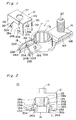
- a battery terminal 10 of the present invention comprises a main terminal 11, tightening tool 12, bolt 13, and nut 14.
- the main terminal 11 is a stud-type terminal formed by bending a single metal plate as shown in the figure, forming a cable connector 16, post fitting 17, and clamping members 18.
- the cable connector 16 is formed by bending a rectangular plate in two horizontally to form top and bottom members 16A and 16B, respectively, and bending the end of the top member 16A down against the bottom member 16B.
- the terminal to which the electrical cable is crimped (not shown in the figures) is secured by a nut (not shown in the figures) to a stud bolt 20 projecting from approximately the center of the top member 16A.
- the post fitting 17 is contiguous to the bottom member 16B of the cable connector 16, and is formed by bending a vertical metal strip perpendicular to the cable connector 16 into a ring shape to form a vertically oriented cylindrical shape.
- Plural vertical grooves 17a are formed at an even interval in the inside circumference wall of the post fitting 17.
- the side of the post fitting 17 opposite the cable connector 16 is open, forming two free ends.
- the clamping members 18 are a pair of right and left clamping members 18A and 18B contiguous to the free ends of the post fitting 17 with a gap S between the clamping members 18A and 18B.
- the right and left clamping members 18A and 18B are connected to the free ends of the vertically oriented post fitting 17, they are formed from similarly vertically oriented metal bands.
- the right and left clamping members 18A and 18B have sliding surfaces 22A and 22B, respectively, sloping down to the outside from the top thereof.
- the bottom end of each sliding surface 22A or 22B is bent horizontally back to the inside forming flats 23A or 23B.
- the inside end of each flat 23A or 23B bends vertically down to form a jam wall 24A or 24B for preventing the rotation of nut 14.
- Claws 25A and 25B projecting into the clamping members 18 are also formed by punching the clamping members 18 in at approximately the center of the sliding surfaces 22A and 22B.
- the tightening tool 12 is an essentially inverted U-shaped member with a top 12a and two sides 12b and 12c, and a bolt hole 27 in the center of the top 12a. Cut-outs 28 and 29 open to the bottom are also provided at the center of the two sides 12b and 12c projecting down from the edges of the top 12a.
- a taper 28a and 28b in side 12b and a taper 29a and 29b (29a not shown in the figures) in side 12c are formed such that they are wider at the bottom than the top and match the slope of the right and left clamping members 18A and 18B of the main terminal 11.
- Claws 30a, 30b, 31a and 31b (31a not shown in the figures) projecting to the inside of the cut-outs 28 and 29 are formed at the bottom ends of the tapers 28a, 28b, 29a and 29b.
- the tightening tool 12 is fit over the clamping members 18A and 18B of the main terminal 11 before the battery terminal 10 is mounted to the battery post 2 (shown in Fig. 4).
- the square nut 14 is then placed between the clamping members 18A and 18B, the bolt 13 is passed through the bolt hole 27 of the tightening tool 12, and is partially threaded into the nut 14 to present a semi-locked state of the battery terminal 10.
- the tapers 28a - 29b of tightening tool 12 can slide against the sliding surfaces 22A and 22B of the main terminal 11, and the bottom ends of the sliding surfaces 22A and 22B contact the claws 30a - 31b of the tightening tool 12.
- the top of the nut 14 is also against the bottom end of the claws 25A and 25B projecting to the inside of the clamping members 18A and 18B.
- the sides of the nut 14 are also held by the jam walls 24A and 24B of the main terminal 11 so that the nut 14 will not turn when the bolt 13 is tightened.
- the battery terminal 10 is first assembled in the semi-locked state as described above, and is fit down onto the battery post 2. Note that the main terminal 11 can be fit easily to the battery post 2 because the free ends of the main terminal 11 post fitting 17 are open.
- An impact wrench or similar tool is then fit to the bolt 13 head, and the bolt 13 is tightened.
- the post fitting 17 is thus clamped against the outside circumference of the battery post 2, and the battery terminal 10 is clamped in positive contact to the battery post 2.
- the thickness of the main terminal 11 can thus be increased in a battery terminal 10 according to the present invention because the post fitting 17 and clamping members 18A, 18B of the main terminal are formed from a single vertically oriented metal band and are extremely simple in shape.
- the plate thickness in this embodiment is approximately 2.0 mm, approximately 0.8 mm thicker than in a conventional battery terminal. This also makes it possible to increase the mechanical strength of the battery terminal 10.
- the battery terminal can also be firmly clamped by tightening a bolt from above because the vertical movement of the tightening tool 12 created by tightening the bolt 13 is converted by means of the tightening tool 12 tapers 28a - 29b and the main terminal 11 sliding surfaces 22A and 22B to the horizontal movement of the free ends of the post fitting 17.
- the post fitting and right and left clamping members are formed from a single vertically oriented metal band in a battery terminal according to the present invention, the shape of the main terminal can be simplified, and the thickness of the metal plate forming the main terminal can be increased as a result. It is thereby possible to increase the mechanical strength of the main terminal, and to prevent deformation of the clamping members when the bolt is tightened.
- the clamping members are bent and sliding surfaces corresponding to the shape of the tightening tool tapers are provided, the downward movement of the tightening tool caused by bolt tightening can be converted by the tightening tool tapers to an inward horizontal movement of the post fitting free ends contiguous to the clamping members.
- the bolt can thus be tightened from above, and the problems associated with tightening the clamping bolt from the side can be eliminated.
Landscapes
- Connection Of Batteries Or Terminals (AREA)
Applications Claiming Priority (2)
| Application Number | Priority Date | Filing Date | Title |
|---|---|---|---|
| JP152/93U | 1993-01-07 | ||
| JP1993000152U JP2600044Y2 (ja) | 1993-01-07 | 1993-01-07 | バッテリー・ターミナル |
Publications (2)
| Publication Number | Publication Date |
|---|---|
| EP0606068A1 true EP0606068A1 (fr) | 1994-07-13 |
| EP0606068B1 EP0606068B1 (fr) | 1997-05-07 |
Family
ID=11466074
Family Applications (1)
| Application Number | Title | Priority Date | Filing Date |
|---|---|---|---|
| EP94100062A Expired - Lifetime EP0606068B1 (fr) | 1993-01-07 | 1994-01-04 | Borne de batterie |
Country Status (4)
| Country | Link |
|---|---|
| US (1) | US5454741A (fr) |
| EP (1) | EP0606068B1 (fr) |
| JP (1) | JP2600044Y2 (fr) |
| DE (1) | DE69402990T2 (fr) |
Cited By (4)
| Publication number | Priority date | Publication date | Assignee | Title |
|---|---|---|---|---|
| EP1180819A3 (fr) * | 2000-08-08 | 2003-02-26 | Harting Automotive GmbH & Co. KG | Borne de batterie |
| ITVI20090235A1 (it) * | 2009-09-28 | 2011-03-29 | Viemme Srl | Morsetto perfezionato di collegamento ai poli di accumulatori elettrici |
| CN105009327A (zh) * | 2013-02-20 | 2015-10-28 | 古河电气工业株式会社 | 蓄电池极柱端子的固定结构 |
| CN109923694A (zh) * | 2016-11-28 | 2019-06-21 | 住友电装株式会社 | 竖直安装的电池熔断器端子 |
Families Citing this family (30)
| Publication number | Priority date | Publication date | Assignee | Title |
|---|---|---|---|---|
| EP0601521B1 (fr) * | 1992-12-07 | 2000-03-08 | Sumitomo Wiring Systems, Ltd. | Cosse de batterie |
| US5885475A (en) * | 1995-06-06 | 1999-03-23 | The University Of Dayton | Phase change materials incorporated throughout the structure of polymer fibers |
| IT237299Y1 (it) * | 1995-11-22 | 2000-09-05 | Cavis Srl | Struttura di morsetto per il collegamento dei poli di una batteria |
| DE19602671A1 (de) * | 1996-01-25 | 1997-07-31 | Amp Gmbh | Anordnung zur Kontaktierung eines konischen Kontaktes |
| US5733152A (en) * | 1996-10-09 | 1998-03-31 | Royal Die & Stamping Co., Inc. | Battery terminal adaptor and connector |
| US5800219A (en) * | 1996-12-17 | 1998-09-01 | United Technologies Automotive, Inc. | Stamped battery terminal |
| US5879202A (en) * | 1997-06-12 | 1999-03-09 | Aluminum Company Of America | Battery terminal connector |
| US6155889A (en) * | 1999-01-06 | 2000-12-05 | Lightning Audio Corporation | Battery terminal connector |
| DE10050217B4 (de) * | 2000-10-11 | 2008-10-02 | Volkswagen Ag | Polanschlußklemme |
| US6561855B1 (en) | 2002-04-04 | 2003-05-13 | Alcoa Fujikura Limited | Clamping mechanism for use with a terminal secured to a battery post and incorporating controlled engagement and spring back characteristics |
| US7718312B2 (en) | 2002-05-27 | 2010-05-18 | Gs Yuasa Corporation | Battery |
| US6855008B1 (en) | 2003-10-06 | 2005-02-15 | Royal Die & Stamping Co., Inc. | Fuse holder with adjustable terminals |
| US6932650B1 (en) | 2004-03-25 | 2005-08-23 | Royal Die & Stamping Co., Inc. | Fused battery terminal connector |
| US20060003627A1 (en) * | 2004-07-01 | 2006-01-05 | Erik Freitag | Fused battery terminal connector |
| JP4584092B2 (ja) * | 2005-09-20 | 2010-11-17 | 矢崎総業株式会社 | バッテリーターミナル |
| JP2009105075A (ja) * | 2009-02-16 | 2009-05-14 | Gs Yuasa Corporation:Kk | 電池 |
| JP5667124B2 (ja) * | 2012-06-01 | 2015-02-12 | 古河電気工業株式会社 | バッテリー端子 |
| JP5973334B2 (ja) * | 2012-12-11 | 2016-08-23 | ナブテスコ株式会社 | 端子接続継ぎ手および端子台 |
| JP5545400B2 (ja) * | 2013-07-22 | 2014-07-09 | 株式会社Gsユアサ | 電池 |
| KR101509987B1 (ko) * | 2013-11-26 | 2015-04-07 | 현대자동차주식회사 | 배터리 단자 체결용 클램프 |
| WO2015087633A1 (fr) * | 2013-12-12 | 2015-06-18 | 矢崎総業株式会社 | Borne de batterie |
| JP2015167107A (ja) * | 2014-03-04 | 2015-09-24 | 住友電装株式会社 | バッテリーターミナル |
| JP6176494B2 (ja) * | 2014-06-09 | 2017-08-09 | 住友電装株式会社 | バッテリ端子 |
| US9608254B1 (en) | 2016-05-26 | 2017-03-28 | Royal Die & Stamping Co., Inc. | Pull bar battery terminal clamp |
| US9774110B1 (en) | 2017-02-10 | 2017-09-26 | Ema-Us, Inc. | Battery post terminal assembly |
| US10008789B1 (en) | 2017-07-10 | 2018-06-26 | Royal Die & Stamping, Llc | Angled bolt T-bar battery terminal clamp |
| CN111801850B (zh) * | 2018-03-08 | 2022-04-12 | 株式会社自动网络技术研究所 | 阴端子 |
| IT201800003963A1 (it) * | 2018-03-26 | 2019-09-26 | Mta Spa | Morsetto per un terminale maschio di una sorgente di energia elettrica. |
| CN110473994B (zh) * | 2018-05-10 | 2022-11-18 | 上海海拉电子有限公司 | 一种车载蓄电池的电瓶栓 |
| JP2024057283A (ja) * | 2022-10-12 | 2024-04-24 | ヤマハ発動機株式会社 | バッテリと鞍乗型車両 |
Citations (3)
| Publication number | Priority date | Publication date | Assignee | Title |
|---|---|---|---|---|
| US1746514A (en) * | 1927-05-20 | 1930-02-11 | Baunach August | Battery terminal |
| US3116100A (en) * | 1962-06-08 | 1963-12-31 | Walter J Hunter | Battery terminal connector |
| EP0451488A1 (fr) * | 1990-04-07 | 1991-10-16 | AUTO-KABEL HAUSEN GmbH & CO. BETRIEBS-KG | Borne de connexion pour accumulateur ou similaire |
Family Cites Families (7)
| Publication number | Priority date | Publication date | Assignee | Title |
|---|---|---|---|---|
| US1645033A (en) * | 1926-08-27 | 1927-10-11 | James J Witkowski | Battery connecter |
| US4367008A (en) * | 1980-12-30 | 1983-01-04 | Thomas & Betts Corporation | Universal battery post connector |
| ES2071144T3 (es) * | 1990-04-07 | 1995-06-16 | Hausen Auto Kabel Gmbh & Co Kg | Borne de conexion para acumulador o similar. |
| JPH049736A (ja) * | 1990-04-27 | 1992-01-14 | Mazda Motor Corp | 合金薄膜のサンプリング方法 |
| JP2574235Y2 (ja) * | 1992-06-09 | 1998-06-11 | 住友電装株式会社 | バッテリー・ターミナル |
| JP2594027Y2 (ja) * | 1992-06-17 | 1999-04-19 | 住友電装株式会社 | バッテリー・ターミナル |
| JP2587000Y2 (ja) * | 1992-09-10 | 1998-12-14 | 住友電装株式会社 | バッテリー・ターミナル |
-
1993
- 1993-01-07 JP JP1993000152U patent/JP2600044Y2/ja not_active Expired - Lifetime
- 1993-12-30 US US08/175,501 patent/US5454741A/en not_active Expired - Fee Related
-
1994
- 1994-01-04 EP EP94100062A patent/EP0606068B1/fr not_active Expired - Lifetime
- 1994-01-04 DE DE69402990T patent/DE69402990T2/de not_active Expired - Fee Related
Patent Citations (3)
| Publication number | Priority date | Publication date | Assignee | Title |
|---|---|---|---|---|
| US1746514A (en) * | 1927-05-20 | 1930-02-11 | Baunach August | Battery terminal |
| US3116100A (en) * | 1962-06-08 | 1963-12-31 | Walter J Hunter | Battery terminal connector |
| EP0451488A1 (fr) * | 1990-04-07 | 1991-10-16 | AUTO-KABEL HAUSEN GmbH & CO. BETRIEBS-KG | Borne de connexion pour accumulateur ou similaire |
Cited By (8)
| Publication number | Priority date | Publication date | Assignee | Title |
|---|---|---|---|---|
| EP1180819A3 (fr) * | 2000-08-08 | 2003-02-26 | Harting Automotive GmbH & Co. KG | Borne de batterie |
| ITVI20090235A1 (it) * | 2009-09-28 | 2011-03-29 | Viemme Srl | Morsetto perfezionato di collegamento ai poli di accumulatori elettrici |
| WO2011036551A1 (fr) | 2009-09-28 | 2011-03-31 | Viemme Srl | Bride de serrage améliorée, destinée à être raccordée aux pôles d'une batterie électrique |
| KR101379623B1 (ko) * | 2009-09-28 | 2014-03-28 | 비엠메 에스알엘 | 전기 배터리의 폴에 연결하기 위한 향상된 클램프 |
| CN105009327A (zh) * | 2013-02-20 | 2015-10-28 | 古河电气工业株式会社 | 蓄电池极柱端子的固定结构 |
| EP2940758A4 (fr) * | 2013-02-20 | 2016-08-24 | Furukawa Electric Co Ltd | Structure pour fixer une borne de plot de batterie |
| CN105009327B (zh) * | 2013-02-20 | 2017-12-08 | 古河电气工业株式会社 | 蓄电池极柱端子的固定结构 |
| CN109923694A (zh) * | 2016-11-28 | 2019-06-21 | 住友电装株式会社 | 竖直安装的电池熔断器端子 |
Also Published As
| Publication number | Publication date |
|---|---|
| US5454741A (en) | 1995-10-03 |
| DE69402990T2 (de) | 1997-12-18 |
| JPH0654205U (ja) | 1994-07-22 |
| DE69402990D1 (de) | 1997-06-12 |
| JP2600044Y2 (ja) | 1999-09-27 |
| EP0606068B1 (fr) | 1997-05-07 |
Similar Documents
| Publication | Publication Date | Title |
|---|---|---|
| US5454741A (en) | Battery terminal | |
| EP0632531B1 (fr) | Cosse de batterie | |
| US5302142A (en) | Battery terminal | |
| EP0601521B1 (fr) | Cosse de batterie | |
| EP0632530B1 (fr) | Cosse de batterie | |
| US7247061B2 (en) | Connector assembly for conductors of a utility power distribution system | |
| US5189258A (en) | Apparatus for directly attaching a strain relief connector to an electrical enclosure | |
| JP2574235Y2 (ja) | バッテリー・ターミナル | |
| US5445907A (en) | Battery terminal | |
| JPH065106U (ja) | バッテリー・ターミナル | |
| EP0575964A1 (fr) | Borne pour accumulateur | |
| CA2087797C (fr) | Appareil servant a assujettir un connecteur de decharge de traction directement a un boitier electrique | |
| US5383796A (en) | Electrical connector with improved strain relief means | |
| US4182928A (en) | Heating element terminal | |
| JP3209107B2 (ja) | バッテリターミナル | |
| CN114843804A (zh) | 用于线缆的两件式接地夹 | |
| US5310365A (en) | Terminal connecting device | |
| EP0615311B1 (fr) | Borne de batterie | |
| JP3004874B2 (ja) | ナットとナット保持部材 | |
| JPH0648166U (ja) | バッテリー・ターミナル | |
| CN222441481U (zh) | 一种电机电容安装卡箍及包含其的接线盒 | |
| JP2593283Y2 (ja) | バッテリー・ターミナル | |
| JPH0521918Y2 (fr) | ||
| JPH0530529U (ja) | クリツプ | |
| JPH065107U (ja) | バッテリー・ターミナル |
Legal Events
| Date | Code | Title | Description |
|---|---|---|---|
| PUAI | Public reference made under article 153(3) epc to a published international application that has entered the european phase |
Free format text: ORIGINAL CODE: 0009012 |
|
| AK | Designated contracting states |
Kind code of ref document: A1 Designated state(s): DE GB |
|
| 17P | Request for examination filed |
Effective date: 19940825 |
|
| 17Q | First examination report despatched |
Effective date: 19950316 |
|
| GRAG | Despatch of communication of intention to grant |
Free format text: ORIGINAL CODE: EPIDOS AGRA |
|
| GRAH | Despatch of communication of intention to grant a patent |
Free format text: ORIGINAL CODE: EPIDOS IGRA |
|
| GRAH | Despatch of communication of intention to grant a patent |
Free format text: ORIGINAL CODE: EPIDOS IGRA |
|
| GRAA | (expected) grant |
Free format text: ORIGINAL CODE: 0009210 |
|
| AK | Designated contracting states |
Kind code of ref document: B1 Designated state(s): DE GB |
|
| REF | Corresponds to: |
Ref document number: 69402990 Country of ref document: DE Date of ref document: 19970612 |
|
| RIN2 | Information on inventor provided after grant (corrected) |
Free format text: OKADA, HAJIME, C/O SUMITOMO WIRING SYSTEMS LTD. |
|
| PLBE | No opposition filed within time limit |
Free format text: ORIGINAL CODE: 0009261 |
|
| STAA | Information on the status of an ep patent application or granted ep patent |
Free format text: STATUS: NO OPPOSITION FILED WITHIN TIME LIMIT |
|
| 26N | No opposition filed | ||
| REG | Reference to a national code |
Ref country code: GB Ref legal event code: IF02 |
|
| PGFP | Annual fee paid to national office [announced via postgrant information from national office to epo] |
Ref country code: GB Payment date: 20020102 Year of fee payment: 9 |
|
| PGFP | Annual fee paid to national office [announced via postgrant information from national office to epo] |
Ref country code: DE Payment date: 20020212 Year of fee payment: 9 |
|
| PG25 | Lapsed in a contracting state [announced via postgrant information from national office to epo] |
Ref country code: GB Free format text: LAPSE BECAUSE OF NON-PAYMENT OF DUE FEES Effective date: 20030104 |
|
| PG25 | Lapsed in a contracting state [announced via postgrant information from national office to epo] |
Ref country code: DE Free format text: LAPSE BECAUSE OF NON-PAYMENT OF DUE FEES Effective date: 20030801 |
|
| GBPC | Gb: european patent ceased through non-payment of renewal fee |
Effective date: 20030104 |