EP0606086A1 - Cassette pour la fixation d'une plaquette de coupe sur un outil à fraiser - Google Patents
Cassette pour la fixation d'une plaquette de coupe sur un outil à fraiser Download PDFInfo
- Publication number
- EP0606086A1 EP0606086A1 EP94100166A EP94100166A EP0606086A1 EP 0606086 A1 EP0606086 A1 EP 0606086A1 EP 94100166 A EP94100166 A EP 94100166A EP 94100166 A EP94100166 A EP 94100166A EP 0606086 A1 EP0606086 A1 EP 0606086A1
- Authority
- EP
- European Patent Office
- Prior art keywords
- cassette
- base body
- pivot axis
- nest
- milling
- Prior art date
- Legal status (The legal status is an assumption and is not a legal conclusion. Google has not performed a legal analysis and makes no representation as to the accuracy of the status listed.)
- Withdrawn
Links
Images

Classifications
-
- B—PERFORMING OPERATIONS; TRANSPORTING
- B23—MACHINE TOOLS; METAL-WORKING NOT OTHERWISE PROVIDED FOR
- B23C—MILLING
- B23C5/00—Milling-cutters
- B23C5/16—Milling-cutters characterised by physical features other than shape
- B23C5/20—Milling-cutters characterised by physical features other than shape with removable cutter bits or teeth or cutting inserts
- B23C5/22—Securing arrangements for bits or teeth or cutting inserts
- B23C5/24—Securing arrangements for bits or teeth or cutting inserts adjustable
- B23C5/2489—Securing arrangements for bits or teeth or cutting inserts adjustable where the adjustment is made by changing the inclination of the inserts
-
- B—PERFORMING OPERATIONS; TRANSPORTING
- B23—MACHINE TOOLS; METAL-WORKING NOT OTHERWISE PROVIDED FOR
- B23C—MILLING
- B23C5/00—Milling-cutters
- B23C5/16—Milling-cutters characterised by physical features other than shape
- B23C5/20—Milling-cutters characterised by physical features other than shape with removable cutter bits or teeth or cutting inserts
- B23C5/22—Securing arrangements for bits or teeth or cutting inserts
- B23C5/2204—Securing arrangements for bits or teeth or cutting inserts with cutting inserts clamped against the walls of the recess in the cutter body by a clamping member acting upon the wall of a hole in the insert
- B23C5/2226—Securing arrangements for bits or teeth or cutting inserts with cutting inserts clamped against the walls of the recess in the cutter body by a clamping member acting upon the wall of a hole in the insert for plate-like cutting inserts fitted on an intermediate carrier, e.g. shank fixed in the cutter body
-
- B—PERFORMING OPERATIONS; TRANSPORTING
- B23—MACHINE TOOLS; METAL-WORKING NOT OTHERWISE PROVIDED FOR
- B23C—MILLING
- B23C5/00—Milling-cutters
- B23C5/16—Milling-cutters characterised by physical features other than shape
- B23C5/20—Milling-cutters characterised by physical features other than shape with removable cutter bits or teeth or cutting inserts
- B23C5/22—Securing arrangements for bits or teeth or cutting inserts
- B23C5/24—Securing arrangements for bits or teeth or cutting inserts adjustable
- B23C5/2472—Securing arrangements for bits or teeth or cutting inserts adjustable the adjusting means being screws
-
- B—PERFORMING OPERATIONS; TRANSPORTING
- B23—MACHINE TOOLS; METAL-WORKING NOT OTHERWISE PROVIDED FOR
- B23C—MILLING
- B23C5/00—Milling-cutters
- B23C5/16—Milling-cutters characterised by physical features other than shape
- B23C5/20—Milling-cutters characterised by physical features other than shape with removable cutter bits or teeth or cutting inserts
- B23C5/22—Securing arrangements for bits or teeth or cutting inserts
- B23C5/24—Securing arrangements for bits or teeth or cutting inserts adjustable
- B23C5/2486—Securing arrangements for bits or teeth or cutting inserts adjustable where the adjustment is made by elastically deforming the toolholders
Definitions
- the invention relates to a cassette, consisting of a lower part which can be inserted into a suitable depression of the base body of a face milling cutter and a corner milling cutter and can be fastened therein by means of external positioning surfaces and counter surfaces of the depression interacting with them in a defined position, optionally with fine adjustment, and one Upper part, which can be fixed in several different angular positions on the lower part and has a nest for receiving an indexable insert in a certain position.
- the invention further relates to a face and shoulder milling cutter equipped with at least one such cassette.
- Face and shoulder milling cutters for various milling angles from z. B. 45 °, 75 ° and 90 ° differ in that square, rectangular or triangular indexable inserts are each set in corresponding positions on the base body of the milling cutter, these positions being determined by holding surfaces on which the edge edges of the screwed or clamped to the base body Fitting indexable inserts. Because of the different positions of the holding surfaces, a different basic body was normally required for each milling angle.
- cassettes In order to make do with a single base body for different milling angles, it is known to use so-called cassettes (cf., for example, catalog "Kennametal", milling tools MM 8515, pages 19-22; DE 37 32 268 A1, DE 33 17 916 C2).
- the cassettes have different nests within a certain system with different holding surfaces for receiving indexable inserts at the desired angle, but all have the same connection dimensions and contact surfaces with which when they are screwed tight, they rest immovably on corresponding counter surfaces of the base body.
- the known cassettes consist of a lower part and an upper part adjustably attached to it, this adjustability only serves for the infinitely variable fine adjustment to a single, specific milling angle.
- DD-PS 37 323 Another state of the art is the DD-PS 37 323 to be mentioned, which describes a milling tool in which it is not cassettes with indexable inserts but milling chisels with different contact surfaces that are used.
- the milling bits can thus be placed in two different orientations on a counter surface on the base body of the milling cutter.
- this does not define the position of the milling cutter relative to the base body. Therefore, like the insert holder of DE 33 17 916 C2, it must be adjusted by hand by means of measuring instruments or gauges by axial displacement and then clamped by means of eccentric shafts.
- DE 34 32 936 A1 describes a deburring tool in which two one-piece cassettes are to be screwed onto each of the annular base bodies, each carrying an indexable insert in a nest.
- pins are screwed into the cassettes, which can be brought into engagement with different pin holes in the base body.
- the one-piece cassette is rotated around the fastening screw, the central longitudinal axis of which thus forms the pivot axis.
- a centering surface surrounding the swivel axis is missing. Because the swivel axis is at a distance from the indexable insert there is a large arc length for the outer corner when pivoting.
- deburring tool would therefore be unsuitable for use on face and shoulder milling cutters.
- a very precisely defined fit of the indexable inserts is required, and because of the normally large number of cassettes to be attached to the circumference of the base body, there is no space for making tangential bores or other centering means under the radially aligned cassettes.
- the invention is based, based on the known cassettes for face and shoulder milling cutters, z. B. according to DE 37 32 268 A1, to provide a cassette which can replace several previously different cassettes and thus reduce the total number of cassettes required and simplifies the changeover.
- the above object is achieved in that the upper part by means of a centering surface formed thereon and a plurality of fixing surfaces arranged eccentrically to a pivot axis determined thereby in such rotational angle positions on the lower part that the milling angle of the main cutting edge is either 45 ° or 90 °, the pivot axis is located in the middle of the insert.
- the different milling angles result from pivoting the upper part of the cassette relative to the lower part.
- the two parts which could be pivoted relative to one another could e.g. B. with a spur toothing (Hirth toothing).
- the contact surfaces have a rotationally symmetrical, for. B. cylindrical or conical centering surface and several eccentrically to a thereby determined pivot axis arranged fixing surfaces, which are preferably pin holes, the central longitudinal axes of which are on the same radius with respect to the pivot axis and extend parallel to this. You only have cylindrical or conical surfaces that can be machined relatively easily with high accuracy.
- the pivot axis is the central longitudinal axis of a threaded bore for a fastening screw. Because the pivot axis is located in the central region of the indexable insert, only a relatively small, insignificant change in the diameter of the milling cutter results from a rotary movement of the nest about the pivot axis. In addition, the cutting forces are absorbed near the cutting edges.
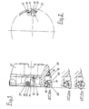
- the base body is denoted by 21, each cassette by a total of 22 and the indexable insert by 23. It is each received in a nest 24 with lateral boundary surfaces 25 and 26, the one Include a right angle and form holding surfaces which determine the position of the indexable insert 22 when it is fixed by means of a clamping wedge 27 and a clamping screw 28.
- Each cassette 22 fits exactly in a depression 29 in the base body 21 and is fixed therein by means of a fastening screw 30 in a certain position.
- an adjusting screw 31 can be screwed into a threaded bore in the base body 1 axial fine adjustment of the cassette 22 can be made.
- Each cassette 22 is formed in two parts. It consists of a lower part 32 and an upper part 33.
- the nest 24 for the indexable insert 23 is worked into the upper part 33.
- This also has a one-piece design on the underside of a pin or peg-shaped projection 34 which sits in a precisely fitting bore in the lower part 32, the central longitudinal axis 35 of which forms a pivot axis. It coincides with the central longitudinal axis of a threaded bore in the upper part 33 of the cassette, into which a connecting screw 36 can be screwed through a through hole in the lower part 32 of the cassette.
- the height of the head of the connecting screw 36 is chosen to be so small that it sits fully recessed in the lower part 32 in the assembled state.
- a positioning pin 37 which can be brought into engagement with one of three pin holes 38 arranged on the same radius with reference to the pivot axis 35, is firmly pressed into this at a distance from the pivot axis 35.
- the indexable insert 22 takes the 90 ° milling angle position shown on the base body 21, or the 75 ° position or 45 ° shown next to the base body 21. Position on.
- the position of the nest 24 and the indexable insert 23 is clearly determined by the contact surfaces of the upper part of the cassette, namely the peripheral surface of the pin 34 and the cylindrical surface of one of the pin holes 38 and the mating surfaces of the lower part 32 of the cassette with the positioning pin 37.
- the rear end of the upper part 33 of the cassette, in which the pin holes 38 are located, is in turn formed in a circular arc with the pivot axis 35 in the center. The same applies to the adjacent step surface of the lower cassette part 32.
- the screw hole for the fastening screw 30 is designated by 39.
- a recess in the corner between the holding surfaces 25 and 26 is designated.
- the positioning pin 37 could also sit in the upper part 33 of the cassette, while the pin holes 38 are located in the lower part 32 of the cassette.
- Another possible modification provides that the indexable insert 23 is not fixed by a clamping wedge, but is screwed to the upper part of the cassette by a screw inserted from above.
Landscapes
- Engineering & Computer Science (AREA)
- Mechanical Engineering (AREA)
- Milling Processes (AREA)
Applications Claiming Priority (2)
| Application Number | Priority Date | Filing Date | Title |
|---|---|---|---|
| DE4300289 | 1993-01-08 | ||
| DE4300289A DE4300289A1 (de) | 1993-01-08 | 1993-01-08 | Kassette zur Befestigung einer Wendeschneidplatte an einem Fräswerkzeug |
Publications (1)
| Publication Number | Publication Date |
|---|---|
| EP0606086A1 true EP0606086A1 (fr) | 1994-07-13 |
Family
ID=6477859
Family Applications (1)
| Application Number | Title | Priority Date | Filing Date |
|---|---|---|---|
| EP94100166A Withdrawn EP0606086A1 (fr) | 1993-01-08 | 1994-01-07 | Cassette pour la fixation d'une plaquette de coupe sur un outil à fraiser |
Country Status (2)
| Country | Link |
|---|---|
| EP (1) | EP0606086A1 (fr) |
| DE (1) | DE4300289A1 (fr) |
Cited By (3)
| Publication number | Priority date | Publication date | Assignee | Title |
|---|---|---|---|---|
| RU2179092C2 (ru) * | 2000-04-10 | 2002-02-10 | Алтайский государственный технический университет им. И.И. Ползунова | Режущий инструмент |
| RU2186659C2 (ru) * | 2000-04-25 | 2002-08-10 | Алтайский государственный технический университет им. И.И.Ползунова | Режущий инструмент |
| US20150336177A1 (en) * | 2014-05-23 | 2015-11-26 | Honda Motor Co., Ltd. | Diamond tip cutting tool |
Families Citing this family (3)
| Publication number | Priority date | Publication date | Assignee | Title |
|---|---|---|---|---|
| DE4436779C2 (de) * | 1994-10-14 | 1996-09-05 | Audi Ag | Spanabhebendes Werkzeug |
| DE10144923A1 (de) | 2001-09-12 | 2003-03-27 | Guehring Joerg | Spanabhebendes Werkzeug mit Wendeschneidplatte |
| DE102009018813B4 (de) | 2009-04-24 | 2023-02-16 | Gühring KG | Werkzeugsystemkomponente |
Citations (5)
| Publication number | Priority date | Publication date | Assignee | Title |
|---|---|---|---|---|
| DD49129A (fr) * | ||||
| EP0069316A1 (fr) * | 1981-07-08 | 1983-01-12 | Carboloy Inc. | Fraise à plaquette de finition réglable |
| DE3432936A1 (de) * | 1984-09-07 | 1986-03-20 | Gerhard 7311 Notzingen Stark | Entgratwerkzeug |
| DE3732268A1 (de) * | 1987-09-25 | 1989-04-06 | Klaus Bronn | Planfraesmesserkopf |
| DE3317916C2 (fr) * | 1983-05-17 | 1992-03-19 | Walter Kieninger Kg Hartmetallwerkzeugfabrik, 7630 Lahr, De |
Family Cites Families (1)
| Publication number | Priority date | Publication date | Assignee | Title |
|---|---|---|---|---|
| DD37323A (fr) * |
-
1993
- 1993-01-08 DE DE4300289A patent/DE4300289A1/de not_active Withdrawn
-
1994
- 1994-01-07 EP EP94100166A patent/EP0606086A1/fr not_active Withdrawn
Patent Citations (5)
| Publication number | Priority date | Publication date | Assignee | Title |
|---|---|---|---|---|
| DD49129A (fr) * | ||||
| EP0069316A1 (fr) * | 1981-07-08 | 1983-01-12 | Carboloy Inc. | Fraise à plaquette de finition réglable |
| DE3317916C2 (fr) * | 1983-05-17 | 1992-03-19 | Walter Kieninger Kg Hartmetallwerkzeugfabrik, 7630 Lahr, De | |
| DE3432936A1 (de) * | 1984-09-07 | 1986-03-20 | Gerhard 7311 Notzingen Stark | Entgratwerkzeug |
| DE3732268A1 (de) * | 1987-09-25 | 1989-04-06 | Klaus Bronn | Planfraesmesserkopf |
Cited By (3)
| Publication number | Priority date | Publication date | Assignee | Title |
|---|---|---|---|---|
| RU2179092C2 (ru) * | 2000-04-10 | 2002-02-10 | Алтайский государственный технический университет им. И.И. Ползунова | Режущий инструмент |
| RU2186659C2 (ru) * | 2000-04-25 | 2002-08-10 | Алтайский государственный технический университет им. И.И.Ползунова | Режущий инструмент |
| US20150336177A1 (en) * | 2014-05-23 | 2015-11-26 | Honda Motor Co., Ltd. | Diamond tip cutting tool |
Also Published As
| Publication number | Publication date |
|---|---|
| DE4300289A1 (de) | 1994-07-14 |
Similar Documents
| Publication | Publication Date | Title |
|---|---|---|
| EP0126432B2 (fr) | Outil de fraisage | |
| DE102008022844B4 (de) | Werkzeug zum Dreh-Dreh-Räumen oder Außenfräsen von Werkstücken | |
| DE2339873C2 (de) | Anordnung zum Einstellen und Befestigen eines ein Schneidplättchen tragenden Blocks in einer nutförmigen Aufnahme im Werkzeugkörper eines spanabhebenden Werkzeugs | |
| EP0131784B1 (fr) | Outil de décroutage | |
| DE69718740T2 (de) | Werkzeugmaschinenschneidewerkzeugpositioniervorrichtung | |
| EP1044081B1 (fr) | Tete de fraisage dotee d'une plaquette a reglage unidimensionnel a tridimensionnel et d'une plaquette fixee par liaison de forme | |
| EP2271451A1 (fr) | Outil de tournage-brochage rotatif ou de fraisage de profil de pièces | |
| EP0407907B1 (fr) | Outillage rotatif d'arasage | |
| EP0353436B1 (fr) | Dispositif d'ajustage, notamment pour des outils | |
| EP0048833B1 (fr) | Outil de fraisage | |
| DE102005045662A1 (de) | Werkzeugrevolver | |
| DE3811775C2 (fr) | ||
| DE19706377C2 (de) | Plan- oder Eckfräser | |
| DE3140905C2 (de) | Planfräsmesserkopf | |
| EP0606086A1 (fr) | Cassette pour la fixation d'une plaquette de coupe sur un outil à fraiser | |
| EP0217035A1 (fr) | Tête porte-lames | |
| EP0143870A1 (fr) | Dispositif auxiliaire pour l'affûtage de forets hélicoidaux | |
| DE3732268A1 (de) | Planfraesmesserkopf | |
| DE4133761C2 (fr) | ||
| DE19846548A1 (de) | Fräswerkzeug | |
| DE19517365B4 (de) | Werkzeughalter | |
| DE3432942C2 (fr) | ||
| DE19917484A1 (de) | Befestigung eines Einzugsnippels an einem Werkstück oder einer Trägerplatte | |
| DE3205202A1 (de) | Fuehrungsvorrichtung zum arbeiten mit einer kraftmaschine | |
| DE2703332A1 (de) | Ausrichtvorrichtung fuer ein bearbeitungswerkzeug |
Legal Events
| Date | Code | Title | Description |
|---|---|---|---|
| PUAI | Public reference made under article 153(3) epc to a published international application that has entered the european phase |
Free format text: ORIGINAL CODE: 0009012 |
|
| AK | Designated contracting states |
Kind code of ref document: A1 Designated state(s): AT BE CH DE ES FR GB IT LI NL PT SE |
|
| STAA | Information on the status of an ep patent application or granted ep patent |
Free format text: STATUS: THE APPLICATION IS DEEMED TO BE WITHDRAWN |
|
| 18D | Application deemed to be withdrawn |
Effective date: 19950114 |