EP0606115B1 - Détecteur avec fonction autocalibrage - Google Patents
Détecteur avec fonction autocalibrage Download PDFInfo
- Publication number
- EP0606115B1 EP0606115B1 EP94103628A EP94103628A EP0606115B1 EP 0606115 B1 EP0606115 B1 EP 0606115B1 EP 94103628 A EP94103628 A EP 94103628A EP 94103628 A EP94103628 A EP 94103628A EP 0606115 B1 EP0606115 B1 EP 0606115B1
- Authority
- EP
- European Patent Office
- Prior art keywords
- electrode means
- displacement
- acceleration
- electrostatic capacity
- exciting voltage
- Prior art date
- Legal status (The legal status is an assumption and is not a legal conclusion. Google has not performed a legal analysis and makes no representation as to the accuracy of the status listed.)
- Expired - Lifetime
Links
- 230000001133 acceleration Effects 0.000 claims description 34
- 238000006073 displacement reaction Methods 0.000 claims description 18
- 238000000034 method Methods 0.000 claims description 9
- 238000012545 processing Methods 0.000 description 13
- 238000001514 detection method Methods 0.000 description 11
- 230000004936 stimulating effect Effects 0.000 description 10
- 238000005259 measurement Methods 0.000 description 8
- 230000006870 function Effects 0.000 description 6
- XUIMIQQOPSSXEZ-UHFFFAOYSA-N Silicon Chemical compound [Si] XUIMIQQOPSSXEZ-UHFFFAOYSA-N 0.000 description 4
- 229910052710 silicon Inorganic materials 0.000 description 4
- 239000010703 silicon Substances 0.000 description 4
- 239000000758 substrate Substances 0.000 description 4
- 238000005516 engineering process Methods 0.000 description 3
- 239000004065 semiconductor Substances 0.000 description 3
- 230000008901 benefit Effects 0.000 description 2
- 230000008859 change Effects 0.000 description 2
- 238000004891 communication Methods 0.000 description 2
- 230000006866 deterioration Effects 0.000 description 2
- 238000005459 micromachining Methods 0.000 description 2
- 230000008569 process Effects 0.000 description 2
- 230000004044 response Effects 0.000 description 2
- 238000004364 calculation method Methods 0.000 description 1
- 239000004020 conductor Substances 0.000 description 1
- 238000012937 correction Methods 0.000 description 1
- 238000003745 diagnosis Methods 0.000 description 1
- 238000010586 diagram Methods 0.000 description 1
- 238000005530 etching Methods 0.000 description 1
- 230000007935 neutral effect Effects 0.000 description 1
- 230000000638 stimulation Effects 0.000 description 1
- 238000012360 testing method Methods 0.000 description 1
Images

Classifications
-
- G—PHYSICS
- G01—MEASURING; TESTING
- G01D—MEASURING NOT SPECIALLY ADAPTED FOR A SPECIFIC VARIABLE; ARRANGEMENTS FOR MEASURING TWO OR MORE VARIABLES NOT COVERED IN A SINGLE OTHER SUBCLASS; TARIFF METERING APPARATUS; MEASURING OR TESTING NOT OTHERWISE PROVIDED FOR
- G01D5/00—Mechanical means for transferring the output of a sensing member; Means for converting the output of a sensing member to another variable where the form or nature of the sensing member does not constrain the means for converting; Transducers not specially adapted for a specific variable
- G01D5/12—Mechanical means for transferring the output of a sensing member; Means for converting the output of a sensing member to another variable where the form or nature of the sensing member does not constrain the means for converting; Transducers not specially adapted for a specific variable using electric or magnetic means
- G01D5/14—Mechanical means for transferring the output of a sensing member; Means for converting the output of a sensing member to another variable where the form or nature of the sensing member does not constrain the means for converting; Transducers not specially adapted for a specific variable using electric or magnetic means influencing the magnitude of a current or voltage
- G01D5/24—Mechanical means for transferring the output of a sensing member; Means for converting the output of a sensing member to another variable where the form or nature of the sensing member does not constrain the means for converting; Transducers not specially adapted for a specific variable using electric or magnetic means influencing the magnitude of a current or voltage by varying capacitance
- G01D5/241—Mechanical means for transferring the output of a sensing member; Means for converting the output of a sensing member to another variable where the form or nature of the sensing member does not constrain the means for converting; Transducers not specially adapted for a specific variable using electric or magnetic means influencing the magnitude of a current or voltage by varying capacitance by relative movement of capacitor electrodes
- G01D5/2417—Mechanical means for transferring the output of a sensing member; Means for converting the output of a sensing member to another variable where the form or nature of the sensing member does not constrain the means for converting; Transducers not specially adapted for a specific variable using electric or magnetic means influencing the magnitude of a current or voltage by varying capacitance by relative movement of capacitor electrodes by varying separation
-
- G—PHYSICS
- G01—MEASURING; TESTING
- G01D—MEASURING NOT SPECIALLY ADAPTED FOR A SPECIFIC VARIABLE; ARRANGEMENTS FOR MEASURING TWO OR MORE VARIABLES NOT COVERED IN A SINGLE OTHER SUBCLASS; TARIFF METERING APPARATUS; MEASURING OR TESTING NOT OTHERWISE PROVIDED FOR
- G01D18/00—Testing or calibrating apparatus or arrangements provided for in groups G01D1/00 - G01D15/00
- G01D18/002—Automatic recalibration
- G01D18/006—Intermittent recalibration
-
- G—PHYSICS
- G01—MEASURING; TESTING
- G01P—MEASURING LINEAR OR ANGULAR SPEED, ACCELERATION, DECELERATION, OR SHOCK; INDICATING PRESENCE, ABSENCE, OR DIRECTION, OF MOVEMENT
- G01P21/00—Testing or calibrating of apparatus or devices covered by the preceding groups
-
- G—PHYSICS
- G01—MEASURING; TESTING
- G01P—MEASURING LINEAR OR ANGULAR SPEED, ACCELERATION, DECELERATION, OR SHOCK; INDICATING PRESENCE, ABSENCE, OR DIRECTION, OF MOVEMENT
- G01P15/00—Measuring acceleration; Measuring deceleration; Measuring shock, i.e. sudden change of acceleration
- G01P15/02—Measuring acceleration; Measuring deceleration; Measuring shock, i.e. sudden change of acceleration by making use of inertia forces using solid seismic masses
- G01P15/08—Measuring acceleration; Measuring deceleration; Measuring shock, i.e. sudden change of acceleration by making use of inertia forces using solid seismic masses with conversion into electric or magnetic values
- G01P2015/0805—Measuring acceleration; Measuring deceleration; Measuring shock, i.e. sudden change of acceleration by making use of inertia forces using solid seismic masses with conversion into electric or magnetic values being provided with a particular type of spring-mass-system for defining the displacement of a seismic mass due to an external acceleration
- G01P2015/0822—Measuring acceleration; Measuring deceleration; Measuring shock, i.e. sudden change of acceleration by making use of inertia forces using solid seismic masses with conversion into electric or magnetic values being provided with a particular type of spring-mass-system for defining the displacement of a seismic mass due to an external acceleration for defining out-of-plane movement of the mass
- G01P2015/0825—Measuring acceleration; Measuring deceleration; Measuring shock, i.e. sudden change of acceleration by making use of inertia forces using solid seismic masses with conversion into electric or magnetic values being provided with a particular type of spring-mass-system for defining the displacement of a seismic mass due to an external acceleration for defining out-of-plane movement of the mass for one single degree of freedom of movement of the mass
- G01P2015/0828—Measuring acceleration; Measuring deceleration; Measuring shock, i.e. sudden change of acceleration by making use of inertia forces using solid seismic masses with conversion into electric or magnetic values being provided with a particular type of spring-mass-system for defining the displacement of a seismic mass due to an external acceleration for defining out-of-plane movement of the mass for one single degree of freedom of movement of the mass the mass being of the paddle type being suspended at one of its longitudinal ends
Definitions
- the present invention relates to an electrostatic capacity type acceleration sensor having a self-calibration function.
- a conventional detector has been, as disclosed in, for example, JP-A- 61-31952, arranged in such a manner that the measuring operation is stopped so as to start a calibrating operation which is performed as the offline work. Furthermore, there has been disclosed, in JP-A- 61-212753, an apparatus capable of diagnosing deterioration by analyzing the characteristics observed in the detector. However, the apparatus of this type also performs, as the offline work, the operation for diagnosing the deterioration.
- the conventional calibration has been realized for the purpose of automating the offline work. Furthermore, there has been a proposal that the reliability of a detector is improved by observing the line and giving an alarm if necessary as the online work. However, since no measure has been taken for performing the calibration as the online work, a problem takes place that the measurement is stopped for a relatively long time in comparison with the time in which the value of the measurement can be changed.
- an electrostatic capacity type acceleration sensor including the features of the first part of claim 1 is known.
- This prior art sensor employs the closed loop technique in which the inertia mass electrode is maintained in a neutral position by applying a voltage. The quantity of this voltage corresponds to the acceleration being effective on the sensor.
- a piezoelectric acceleration sensor is known in which an actuator in form of the piezoelectric plate is provided to diagnose the sensor portion. By applying a test voltage to the piezoelectric plate the sensor portion is deformed so as to measure a voltage to diagnose this portion.
- the calibration or the corrective operation In a sensor, the calibration or the corrective operation must be completed in a significantly short time in comparison with the time in which the value of the measurement can be changed.
- the reason for this lies in that the data of the measurement must be protected from a disorder or an error due to the calibration or the corrective operation performed during the measurement operation.
- the device for processing an electric signal significantly high speed semiconductor ICs are available recently due to the progress of the LSI technology. Therefore, the thus realized speed of processing the electric signal can cope with the time of several tens to 100 ⁇ s which is the value necessary to conduct measurements in automobile in which the values to be measured are varied in a relatively short time.
- the present invention employs stimulating means disposed adjacent to the detection means so as to stimulate and operate the detection means.
- a structure can be realized in which a small sensor, the size of which is, for example, several hundreds of ⁇ m, and an actuator, that is, the stimulating device can be integrally formed by utilizing the micromachining technology for silicon or the like which has been remarkably progressed recently. Therefore, a compact and integrally formed stimulating device is able to apply a calibration signal, as a stimulation, to the detector without delay.
- the sensor according to the present invention is preferably structured such that the stimulating means is formed adjacent to and integrally with the detection means so that the calibration signal can be supplied through the stimulating means. Therefore, the delay of response from the sensor can be significantly prevented. Furthermore, a high-speed signal processing circuit can be employed to shorten the time required for completing the self-calibration in comparison to the time in. which the values to be measured are changed. Therefore, even if the self-calibration is performed during the measurement operation, the output from the sensor can be protected from disorder. Therefore, a so-called "online calibration" can be realized.
- the characteristics obtained during operation are always corrected in accordance with a comparison made with the initial characteristics of the sensor based on a calibration and corrective algorithm previously prepared in the processing means. Therefore, the initial performance can be maintained to significantly improve the reliability.
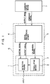
- Reference numeral 1 represents detection means and 2 represents stimulating means disposed adjacent to the detection means 2 and integrally therewith.
- Reference numeral 3 represents an assembly of the detection means 1 and the stimulating means 2.
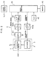
- Reference numeral 4 represents a signal processing means structured as shown in Fig. 2 and arranged to supply a power supply voltage Ex for operating the detection means 1 and the stimulating means 2 and to process a calibrating signal to be supplied to the stimulating means 2. Furthermore, the signal processing means 4 has a so-called “signal adjustment function" capable of amplifying/converting a responding output signal from the detection means 1.
- the signal processing means 4 has a function of calibrating the input/output and a characteristic corrective function realized by digital-data processing performed by a microcomputer 44.
- Reference numeral 5 represents a detector including the above-described elements. Usually, the detector converts an acceleration into a digital quantity of a certain number of bits so as to output it.
- Reference numeral 7 represents a communication device capable of transmitting/receiving a command signal and an output signal to and from the signal processing means 4, the communication device 7 further having a function of displaying the command signal and the output signal.
- Fig. 2 illustrates the specific structure of a circuit serving as the signal processing means 4.
- a multiplexer 411 is operated so as to cause the output signal transmitted from the detection means 1 to be received by an amplifier 412a and an analogto-digital converter 42.
- the output signal thus received is converted into a digital signal.
- the signal processing means 4 supplies the power supply voltage Ex from a power source 43 or supplies the calibration signal to the stimulating means 2 via another amplifier 412b. As a result, an accurate detection signal capable of correcting an error can be obtained.
- Fig. 3 illustrates basic structures of semiconductor acceleration sensor of an electrostatic capacity type being manufactured by a silicon micromachining technology.
- the acceleration sensor is for obtaining an acceleration by a measurement of an inertia force acting on a predetermined mass in the case where the acceleration exists.
- the acceleration sensor shown in Fig. 3 is structured such that a load 53 and a cantilever 54 for supporting the load 53 are formed on an intermediate silicon substrate 51 by anisotropic etching.
- F 1 m ⁇
- a a spring constant
- x denotes the amount of displacement
- the acceleration ⁇ can be obtained from the displacement x.
- the electrostatic capacity type acceleration sensor shown in Fig. 3 includes an upper fixed electrode 55a and a lower fixed electrode 55b formed on the surfaces of the upper substrate 52a and the lower substrate 52b which face the intermediate silicon substrate 51.
- the fixed electrodes 55a and 55b are electrically connected by conductors 56a and 56b to terminals 57a and 57b, respectively.
- the electrostatic capacity type acceleration sensor acts to measure the acceleration by obtaining the displacement x of the Equation (I) from the electrostatic capacity between the fixed electrodes and the load (movable electrode).
- Equation (III) In the case where p(t) and q(t) are unknown in Equation (III), they can be obtained by generating two different accelerations ⁇ 1 and ⁇ 2 by some method so as to measure the outputs V( ⁇ 1 , t) and V( ⁇ 2 , t) which correspond to the two accelerations ⁇ 1 and ⁇ 2 . Namely, P(t) and q(t) can be obtained from the following simultaneous equation:
- Equation (I) corresponds to the displacement x of the load in the relationship given by Equation (I). Therefore, determining the acceleration ⁇ 1 and ⁇ 2 becomes equivalent to determining the displacements x 1 and x 2 which correspond to the accelerations ⁇ 1 and ⁇ 2 .
- the predetermined displacements x 1 and x 2 shown in Equation (5) can be relatively easily realized. That is, the structure may be such that the load is forcibly displaced by an actuator and the characteristics of the sensor output V(x, t) sharply varies at the predetermined certain displacements x 1 and x 2 . As an alternative to this, the structure may be such that any further displacement is inhibited.
- Fig. 4 illustrates an example of the above-described structure, in which stoppers 60a and 60b are provided for the purpose of preventing any displacement which exceeds a predetermined degree even if an acceleration or an external force acts on the load. If the displacements x 1 and x 2 obtained when the loads are brought into contact with the stoppers 60a and 60b are previously known, p(t) and q(t) can be obtained from Equations (V) and (VI) by measuring the outputs V(x 1 , t) and V(x 2 , t) at this time.
- an advantage can be obtained that the change in the acceleration-output characteristics as the time proceeds can be corrected by a simple calculation from the output obtained by periodically applying a voltage between the fixed electrodes and the load. Furthermore, the correction can be performed even if the acceleration is being applied to the sensor.
Landscapes
- Physics & Mathematics (AREA)
- General Physics & Mathematics (AREA)
- Engineering & Computer Science (AREA)
- Power Engineering (AREA)
- Combined Controls Of Internal Combustion Engines (AREA)
- Investigating Or Analyzing Materials By The Use Of Electric Means (AREA)
- Measuring Fluid Pressure (AREA)
- Micromachines (AREA)
- Pressure Sensors (AREA)
Claims (4)
- Détecteur d'accélération du type à capacité électrostatique comportantcaractérisé en ce qu'il comporte de plusdes premiers moyens d'électrode (55a, 55b), etdes seconds moyens d'électrode (53) disposés de manière espacée desdits premiers moyens d'électrode et supportés par des moyens de ressort souple (54) pour se déplacer vers lesdits premiers moyens d'électrode et s'écarter de ceux-ci,des moyens (2, 412b) pour appliquer une tension d'excitation à travers lesdits premiers et seconds moyens d'électrode de manière à déplacer lesdits seconds moyens d'électrode (53), etdes moyens (4) pour mesurer un déplacement desdits seconds moyens d'électrode (53), provoqué par l'application de la tension d'excitation, sur la base d'une variation de la capacité électrostatique existant entre lesdits premiers et seconds moyens d'électrode et pour comparer le déplacement détecté à une relation mémorisée existant entre une tension d'excitation et un déplacement des seconds moyens d'électrode pour un diagnostic en ligne du détecteur.
- Détecteur d'accélération selon la revendication 1, dans lequel lesdits premiers moyens d'électrode comportent deux électrodes fixées de manière stationnaire (55a, 55b) disposées sur les côtés opposés desdits seconds moyens d'électrode (53) et se faisant face l'une l'autre.
- Procédé de diagnostic en ligne d'un détecteur d'accélération du type à capacité électrostatique qui comporte des premiers moyens d'électrode (55a, 55b) et des seconds moyens d'électrode (53) pouvant se déplacer vers lesdits premiers moyens d'électrode et s'écarter de ceux-ci, le procédé comportant les étapes consistant à :(a) appliquer une tension d'excitation à travers lesdits premiers et seconds moyens d'électrode (53, 55a, 55b) de manière à déplacer lesdits seconds moyens d'électrode (53),(b) détecter le déplacement desdits seconds moyens d'électrode (53), provoqué par l'application de la tension d'excitation, sur la base d'une variation de la capacité électrostatique existant entre lesdits premiers et seconds moyens d'électrode, et(c) comparer le déplacement détecté à une relation mémorisée existant entre une tension d'excitation et un déplacement desdits seconds moyens d'électrode.
- Procédé selon la revendication 3, dans lequel ladite tension d'excitation est sous la forme d'une tension pulsée.
Applications Claiming Priority (3)
| Application Number | Priority Date | Filing Date | Title |
|---|---|---|---|
| JP1271666A JPH03134552A (ja) | 1989-10-20 | 1989-10-20 | 自己較正機能付検出装置 |
| JP271666/89 | 1989-10-20 | ||
| EP90119524A EP0423622B2 (fr) | 1989-10-20 | 1990-10-11 | Détecteur avec fonction autocalibrage |
Related Parent Applications (2)
| Application Number | Title | Priority Date | Filing Date |
|---|---|---|---|
| EP90119524A Division EP0423622B2 (fr) | 1989-10-20 | 1990-10-11 | Détecteur avec fonction autocalibrage |
| EP90119524.8 Division | 1990-10-11 |
Publications (2)
| Publication Number | Publication Date |
|---|---|
| EP0606115A1 EP0606115A1 (fr) | 1994-07-13 |
| EP0606115B1 true EP0606115B1 (fr) | 1998-02-04 |
Family
ID=17503194
Family Applications (2)
| Application Number | Title | Priority Date | Filing Date |
|---|---|---|---|
| EP94103628A Expired - Lifetime EP0606115B1 (fr) | 1989-10-20 | 1990-10-11 | Détecteur avec fonction autocalibrage |
| EP90119524A Expired - Lifetime EP0423622B2 (fr) | 1989-10-20 | 1990-10-11 | Détecteur avec fonction autocalibrage |
Family Applications After (1)
| Application Number | Title | Priority Date | Filing Date |
|---|---|---|---|
| EP90119524A Expired - Lifetime EP0423622B2 (fr) | 1989-10-20 | 1990-10-11 | Détecteur avec fonction autocalibrage |
Country Status (5)
| Country | Link |
|---|---|
| US (4) | US5174884A (fr) |
| EP (2) | EP0606115B1 (fr) |
| JP (1) | JPH03134552A (fr) |
| KR (1) | KR0175300B1 (fr) |
| DE (2) | DE69032031T2 (fr) |
Cited By (3)
| Publication number | Priority date | Publication date | Assignee | Title |
|---|---|---|---|---|
| DE102004039463A1 (de) * | 2004-08-14 | 2006-02-23 | Hella Kgaa Hueck & Co. | Sensor und Verfahren zur Kalibrierung eines Sensors |
| DE10046958B4 (de) * | 1999-09-27 | 2009-01-02 | Denso Corp., Kariya-shi | Kapazitive Vorrichtung zum Erfassen einer physikalischen Grösse |
| CN100514010C (zh) * | 2006-03-28 | 2009-07-15 | 中国科学院声学研究所 | 具有在线自标定功能的水听器 |
Families Citing this family (62)
| Publication number | Priority date | Publication date | Assignee | Title |
|---|---|---|---|---|
| DE3844333A1 (de) * | 1988-12-30 | 1990-07-05 | Bosch Gmbh Robert | Verfahren und vorrichtung zur korrektur von bauteiltoleranzen bei der verarbeitung von signalen |
| JPH03134552A (ja) * | 1989-10-20 | 1991-06-07 | Hitachi Ltd | 自己較正機能付検出装置 |
| US5461916A (en) | 1992-08-21 | 1995-10-31 | Nippondenso Co., Ltd. | Mechanical force sensing semiconductor device |
| DE4318891A1 (de) * | 1993-06-07 | 1994-12-08 | Mannesmann Ag | Elektrochemisches Gasspurenmeßsystem mit Funktionskontrolle |
| EP0715722B1 (fr) * | 1993-08-24 | 1998-06-03 | A/S BRÜEL & KJAER | Appareil de detection d'une defaillance dans un accelerometre |
| US5446682A (en) * | 1994-03-21 | 1995-08-29 | Square D Company | System for calibrating a line isolation monitor |
| US5448491A (en) * | 1994-03-21 | 1995-09-05 | Square D Company | Monitor for an ungrounded system |
| US5450328A (en) * | 1994-03-21 | 1995-09-12 | Square D Company | System for measuring line to ground impedance |
| JP2586406B2 (ja) * | 1994-10-27 | 1997-02-26 | 日本電気株式会社 | 静電容量型加速度センサ |
| US5565625A (en) | 1994-12-01 | 1996-10-15 | Analog Devices, Inc. | Sensor with separate actuator and sense fingers |
| US5587518A (en) * | 1994-12-23 | 1996-12-24 | Ford Motor Company | Accelerometer with a combined self-test and ground electrode |
| GB9426220D0 (en) * | 1994-12-23 | 1995-02-22 | Lucas Ind Plc | Vehicle load measuring systems |
| JP3433401B2 (ja) * | 1995-05-18 | 2003-08-04 | アイシン精機株式会社 | 静電容量型加速度センサ |
| US5621157A (en) * | 1995-06-07 | 1997-04-15 | Analog Devices, Inc. | Method and circuitry for calibrating a micromachined sensor |
| US5596144A (en) * | 1995-08-04 | 1997-01-21 | Delco Electronics Corporation | Piezoresistive force rebalance accelerometer |
| DE19601078C2 (de) * | 1996-01-13 | 2000-01-05 | Bosch Gmbh Robert | Druckkraftsensor |
| DE19606826A1 (de) * | 1996-02-23 | 1997-08-28 | Knorr Bremse Electronic Gmbh | Verfahren und Vorrichtung zur Überprüfung eines Sensors |
| JP3125675B2 (ja) * | 1996-03-29 | 2001-01-22 | 三菱電機株式会社 | 容量型センサインターフェース回路 |
| JPH10132848A (ja) * | 1996-10-31 | 1998-05-22 | Akebono Brake Ind Co Ltd | 半導体加速度センサー |
| EP0926470A4 (fr) * | 1997-07-14 | 2005-06-15 | Matsushita Electric Industrial Co Ltd | Capteur dote d'une fonction de reglage |
| DE19739903A1 (de) * | 1997-09-11 | 1999-04-01 | Bosch Gmbh Robert | Sensorvorrichtung |
| EP1169657A4 (fr) * | 1999-03-17 | 2003-03-05 | Input Output Inc | Etalonnage de sondes |
| US6758080B1 (en) | 1999-03-17 | 2004-07-06 | Input/Output, Inc. | Calibration of sensors |
| US6836238B1 (en) * | 2001-10-09 | 2004-12-28 | Escort Inc. | Police radar/laser detector with integral vehicle parameter display using a vehicle interface |
| DE50008129D1 (de) * | 1999-06-15 | 2004-11-11 | Siemens Ag | Messumformer |
| NO313605B1 (no) * | 1999-12-13 | 2002-10-28 | Optoplan As | Fremgangsmate og system for kalibrering av en konverteringsenhet i et fiberoptisk sensorhode |
| DE10065833C2 (de) * | 2000-12-28 | 2002-11-14 | Balluff Gmbh | Parametrierbarer Sensor und Verfahren zur Parametrierung eines Sensors |
| DE10131760B4 (de) * | 2001-06-30 | 2012-06-21 | Robert Bosch Gmbh | Verfahren zum Testen eines Sensors |
| US6510628B1 (en) * | 2001-10-31 | 2003-01-28 | Caterpillar Inc | Method and apparatus for determining a contact force of a work tool |
| DE10162334A1 (de) * | 2001-12-18 | 2003-07-03 | Endress & Hauser Gmbh & Co Kg | Feldgerät und ein Verfahren zur Kalibrierung eines Feldgerätes |
| US7004030B2 (en) * | 2002-09-27 | 2006-02-28 | Oki Electric Industry Co., Ltd. | Acceleration sensor |
| DE10357870B4 (de) * | 2003-12-11 | 2013-02-07 | Robert Bosch Gmbh | Sensor mit symmetrischer Begrenzung eines Signals |
| US7043960B1 (en) * | 2004-06-17 | 2006-05-16 | The United States Of America As Represented By The Administrator Of The National Aeronautics And Space Administration | Self-calibrating pressure transducer |
| DE502005003978D1 (de) * | 2005-04-01 | 2008-06-19 | Mettler Toledo Ag | Verfahren und Vorrichtung zur Funktionskontrolle eines Sensors |
| CN101189563B (zh) * | 2005-05-31 | 2013-03-13 | 博格华纳公司 | 执行器控制方法 |
| JP4758145B2 (ja) * | 2005-06-03 | 2011-08-24 | シチズンホールディングス株式会社 | 接触燃焼式ガスセンサ |
| US7293466B2 (en) * | 2005-07-19 | 2007-11-13 | Hitachi, Ltd. | Bolt with function of measuring strain |
| DE102006005835A1 (de) * | 2006-02-08 | 2007-08-16 | Logicdata Electronic & Software Entwicklungs Gmbh | Schaltungsanordnung und Verfahren zur Kalibrierung einer Sensoranordnung, insbesondere für motorisch verstellbare Möbel, sowie Messverstärker und Sensoranordnung |
| JP2007212292A (ja) * | 2006-02-09 | 2007-08-23 | Mitsubishi Electric Corp | 磁気検出装置 |
| CN101000249B (zh) * | 2007-01-04 | 2011-01-26 | 钟胜 | 柔性铰链电容传感器机芯及使用该机芯的传感器 |
| DE602007010581D1 (de) | 2007-02-21 | 2010-12-30 | Em Microelectronic Marin Sa | Automatischer Test einer elektronischen Schaltungsanordnung eines kapazitiven Sensors, und elektronische Schaltungsanordnung zur Ausführung des Testes |
| DE102007051885A1 (de) * | 2007-10-30 | 2009-05-07 | Lucas Automotive Gmbh | Technik zum Überprüfen eines Kraftfahrzeug-Sensors |
| DE102008040529B4 (de) * | 2008-07-18 | 2021-05-06 | Robert Bosch Gmbh | Fehlerkorrekturverfahren und Fehlerkorrekturvorrichtung für einen Beschleunigungssensor |
| JP4894840B2 (ja) * | 2008-10-08 | 2012-03-14 | 株式会社デンソー | 物理量検出装置 |
| US8554615B2 (en) * | 2009-02-24 | 2013-10-08 | Board Of Trustees Of Michigan State University | Context-induced wireless network transport for content and profile information |
| DE102010029903A1 (de) * | 2010-06-10 | 2011-12-15 | Robert Bosch Gmbh | Sensoranordnung und Verfahren zur Online-Überwachung einer Sensoranordnung |
| US9065358B2 (en) * | 2011-07-11 | 2015-06-23 | Taiwan Semiconductor Manufacturing Company, Ltd. | MEMS structure and method of forming same |
| JP2013122380A (ja) * | 2011-12-09 | 2013-06-20 | Seiko Instruments Inc | 加速度信号処理装置 |
| US9335396B2 (en) * | 2013-03-12 | 2016-05-10 | Freescale Semiconductor, Inc. | MCU-based compensation and calibration for MEMS devices |
| US20140361793A1 (en) * | 2013-05-30 | 2014-12-11 | Tech4Imaging Llc | Interactive and Adaptive Data Acquisition System for Use with Electrical Capacitance Volume Tomography |
| DE202014006185U1 (de) * | 2013-08-12 | 2014-11-26 | Horiba Ltd. | Kraftstoffverbrauch-Berechnungseinheit, Kraftstoffverbrauch-Berechnungsprogramm, Kraftstoffverbrauch-Messgerät und Abgas-Messgerät |
| US9110115B2 (en) | 2013-08-13 | 2015-08-18 | Tech4Imaging Llc | Modular stretchable and flexible capacitance sensors for use with electrical capacitance volume tomography and capacitance sensing applications |
| US9901282B2 (en) | 2015-04-27 | 2018-02-27 | Tech4Imaging Llc | Multi-phase flow decomposition using electrical capacitance volume tomography sensors |
| US10488236B2 (en) | 2016-02-23 | 2019-11-26 | Tech4Imaging Llc | Velocity vector field mapping using electrical capacitance sensors |
| US9958408B2 (en) | 2016-05-11 | 2018-05-01 | Tech4Imaging Llc | Smart capacitance sensors for use with electrical capacitance volume tomography and capacitance sensing applications |
| KR101663815B1 (ko) * | 2016-06-03 | 2016-10-10 | (주)테크윈시스템 | 초음파 레벨 자동 측정장치 |
| US10281422B2 (en) | 2016-09-12 | 2019-05-07 | Tech4Imaging Llc | Displacement current phase tomography for imaging of lossy medium |
| US10502655B2 (en) | 2017-03-07 | 2019-12-10 | Tech4Imaging Llc | Magnetic pressure sensors system for measurement and imaging of steel mass |
| DE102018111380A1 (de) * | 2017-05-24 | 2018-11-29 | HELLA GmbH & Co. KGaA | Verfahren zur Kalibrierung mindestens eines Sensors |
| US10705043B2 (en) | 2017-05-31 | 2020-07-07 | Tech4Imaging Llc | Multi-dimensional approach to imaging, monitoring, or measuring systems and processes utilizing capacitance sensors |
| CN118894489B (zh) * | 2024-09-11 | 2025-06-06 | 无锡国芯微高新技术有限公司 | Mems传感器自校准系统和自校准方法 |
| DE102025102130B3 (de) | 2025-01-22 | 2026-04-02 | Deutsches Zentrum für Luft- und Raumfahrt e.V. | Selbsttest eines Inertialsensors |
Family Cites Families (20)
| Publication number | Priority date | Publication date | Assignee | Title |
|---|---|---|---|---|
| US4225851A (en) * | 1979-03-22 | 1980-09-30 | General Electric Company | Self-calibrated subcarrier telemetry system |
| JPS562548A (en) * | 1979-06-22 | 1981-01-12 | Nissan Motor Co Ltd | Controller for air fuel ratio of internal combustion engine |
| US4556472A (en) * | 1982-04-19 | 1985-12-03 | Board Of Governors For Higher Education, State Of Ri | Computerized device for pulsed potential voltammetric measurement of oxygen using a membrance covered polarographic electrode |
| JPS6131952A (ja) * | 1984-07-25 | 1986-02-14 | Horiba Ltd | 自動校正機能付濃度計 |
| FR2578323B1 (fr) * | 1985-03-01 | 1987-11-20 | Metravib Sa | Capteur integre de grandeurs mecaniques a effet capacitif et procede de fabrication. |
| JPS61212753A (ja) * | 1985-03-18 | 1986-09-20 | Fujikura Ltd | 酸素センサ−の自己診断方法 |
| GB2174812B (en) * | 1985-03-19 | 1989-06-21 | Honda Motor Co Ltd | Oxygen concentration system |
| US4638669A (en) * | 1985-05-07 | 1987-01-27 | Massachusetts Institute Of Technology | Quantum tunneling cantilever accelerometer |
| US4679434A (en) * | 1985-07-25 | 1987-07-14 | Litton Systems, Inc. | Integrated force balanced accelerometer |
| US4673870A (en) * | 1985-08-07 | 1987-06-16 | The United States Of America As Represented By The Secretary Of The Army | Automated calibration technique for non-field perturbing (electrically small) electromagnetic field sensors |
| DE3542397A1 (de) * | 1985-11-30 | 1987-06-04 | Philips Patentverwaltung | Anordnung zur funktionspruefung von piezoelektrischen beschleunigungsaufnehmern |
| IT1213111B (it) * | 1986-07-24 | 1989-12-07 | Nicotra Sistemi | Trasduttore singolo/multiplo, atto a rilevare una o piu' grandezze fisiche di diversa natura o variabili elettriche convenzionali. |
| DE3627241A1 (de) * | 1986-08-12 | 1988-02-18 | Bosch Gmbh Robert | Schaltung und verfahren zur ueberpruefung elektronischer sensoren |
| GB8723339D0 (en) * | 1987-10-05 | 1987-11-11 | Kellett M A | Transducer control circuits |
| JPH0827247B2 (ja) * | 1987-11-04 | 1996-03-21 | 株式会社豊田中央研究所 | 広帯域空燃比センサおよび検出装置 |
| CA1330265C (fr) * | 1988-09-23 | 1994-06-21 | Craig W. White | Accelerometre a etalonnage automatique |
| US5163325A (en) * | 1988-09-23 | 1992-11-17 | Automotive Systems Laboratory, Inc. | Self-compensating accelerometer |
| JPH0623782B2 (ja) * | 1988-11-15 | 1994-03-30 | 株式会社日立製作所 | 静電容量式加速度センサ及び半導体圧力センサ |
| US5103667A (en) * | 1989-06-22 | 1992-04-14 | Ic Sensors, Inc. | Self-testable micro-accelerometer and method |
| JPH03134552A (ja) * | 1989-10-20 | 1991-06-07 | Hitachi Ltd | 自己較正機能付検出装置 |
-
1989
- 1989-10-20 JP JP1271666A patent/JPH03134552A/ja active Pending
-
1990
- 1990-10-10 US US07/595,824 patent/US5174884A/en not_active Expired - Lifetime
- 1990-10-11 DE DE69032031T patent/DE69032031T2/de not_active Expired - Fee Related
- 1990-10-11 EP EP94103628A patent/EP0606115B1/fr not_active Expired - Lifetime
- 1990-10-11 EP EP90119524A patent/EP0423622B2/fr not_active Expired - Lifetime
- 1990-10-11 DE DE69016346T patent/DE69016346T3/de not_active Expired - Fee Related
- 1990-10-18 KR KR1019900016579A patent/KR0175300B1/ko not_active Expired - Fee Related
-
1992
- 1992-12-07 US US07/985,654 patent/US5391283A/en not_active Expired - Lifetime
-
1994
- 1994-11-14 US US08/339,709 patent/US5429736A/en not_active Expired - Lifetime
-
1995
- 1995-05-30 US US08/452,698 patent/US5574211A/en not_active Expired - Lifetime
Cited By (3)
| Publication number | Priority date | Publication date | Assignee | Title |
|---|---|---|---|---|
| DE10046958B4 (de) * | 1999-09-27 | 2009-01-02 | Denso Corp., Kariya-shi | Kapazitive Vorrichtung zum Erfassen einer physikalischen Grösse |
| DE102004039463A1 (de) * | 2004-08-14 | 2006-02-23 | Hella Kgaa Hueck & Co. | Sensor und Verfahren zur Kalibrierung eines Sensors |
| CN100514010C (zh) * | 2006-03-28 | 2009-07-15 | 中国科学院声学研究所 | 具有在线自标定功能的水听器 |
Also Published As
| Publication number | Publication date |
|---|---|
| DE69032031T2 (de) | 1998-10-01 |
| US5391283A (en) | 1995-02-21 |
| EP0423622A1 (fr) | 1991-04-24 |
| DE69032031D1 (de) | 1998-03-12 |
| EP0423622B1 (fr) | 1995-01-25 |
| US5174884A (en) | 1992-12-29 |
| EP0423622B2 (fr) | 1999-06-02 |
| DE69016346T2 (de) | 1995-05-24 |
| KR910008380A (ko) | 1991-05-31 |
| DE69016346D1 (de) | 1995-03-09 |
| US5429736A (en) | 1995-07-04 |
| US5574211A (en) | 1996-11-12 |
| EP0606115A1 (fr) | 1994-07-13 |
| DE69016346T3 (de) | 2000-02-03 |
| KR0175300B1 (ko) | 1999-05-15 |
| JPH03134552A (ja) | 1991-06-07 |
Similar Documents
| Publication | Publication Date | Title |
|---|---|---|
| EP0606115B1 (fr) | Détecteur avec fonction autocalibrage | |
| US5465604A (en) | Method for adjusting sensitivity of a sensor | |
| EP1069437A1 (fr) | Procede de commande de manipulation d'ic, systeme de commande dans lequel ledit procede est utilise | |
| EP3977141B1 (fr) | Systèmes et procédés de test de force en mode continu | |
| US6007728A (en) | Design of a novel tactile sensor | |
| US5612488A (en) | Semiconductor acceleration detecting device | |
| JPH0712667A (ja) | 物理量センサおよび物理量センサシステム | |
| JP3145040B2 (ja) | 静電容量式加速度センサ | |
| EP1794598B1 (fr) | Procedes et dispositifs pour reduire des erreurs de rectification de vibration dans des accelerometres a boucle fermee | |
| US6430520B1 (en) | Dynamic friction measurement apparatus and method | |
| EP0274201A1 (fr) | Accéléromètre | |
| JP3173504B2 (ja) | 加速度検出装置および静電容量式加速度検出装置 | |
| JP3279488B2 (ja) | 物理量センサの校正方法と校正装置 | |
| WO1998015809A1 (fr) | Capteur a semi-conducteur presentant une fonction de diagnostic et procede de diagnostic pour capteur a semi-conducteur | |
| SU1138750A1 (ru) | Полупроводниковый тензопреобразователь | |
| JPH0252212B2 (fr) | ||
| CN120405181A (zh) | Mems加速度计的质量块偏转自测试 | |
| JPH03162630A (ja) | 荷重検出装置 | |
| JPH074488Y2 (ja) | 接触検出装置 | |
| JP2001124682A (ja) | 硬さ試験機および硬さ試験機における機体歪み補正方法 | |
| JPH08152433A (ja) | 光学式加速度センサ | |
| JP2000042973A (ja) | 微小力印加装置 | |
| JPH0875783A (ja) | 半導体式加速度センサ | |
| JPH05322548A (ja) | 変位検出センサーの検査装置 |
Legal Events
| Date | Code | Title | Description |
|---|---|---|---|
| PUAI | Public reference made under article 153(3) epc to a published international application that has entered the european phase |
Free format text: ORIGINAL CODE: 0009012 |
|
| 17P | Request for examination filed |
Effective date: 19940321 |
|
| AC | Divisional application: reference to earlier application |
Ref document number: 423622 Country of ref document: EP |
|
| AK | Designated contracting states |
Kind code of ref document: A1 Designated state(s): DE FR GB |
|
| RIN1 | Information on inventor provided before grant (corrected) |
Inventor name: YOKOTA, YOSHIHIRO Inventor name: KUROIWA, HIROSHI Inventor name: KANEYASU, MASAYOSHI Inventor name: UGAI, SEIICHI Inventor name: TSUCHITANI, SHIGEKI Inventor name: SUZUKI, SEIKO Inventor name: SHIMADA, SATOSHI |
|
| 17Q | First examination report despatched |
Effective date: 19960307 |
|
| GRAG | Despatch of communication of intention to grant |
Free format text: ORIGINAL CODE: EPIDOS AGRA |
|
| GRAG | Despatch of communication of intention to grant |
Free format text: ORIGINAL CODE: EPIDOS AGRA |
|
| GRAH | Despatch of communication of intention to grant a patent |
Free format text: ORIGINAL CODE: EPIDOS IGRA |
|
| GRAH | Despatch of communication of intention to grant a patent |
Free format text: ORIGINAL CODE: EPIDOS IGRA |
|
| GRAA | (expected) grant |
Free format text: ORIGINAL CODE: 0009210 |
|
| AC | Divisional application: reference to earlier application |
Ref document number: 423622 Country of ref document: EP |
|
| AK | Designated contracting states |
Kind code of ref document: B1 Designated state(s): DE FR GB |
|
| REF | Corresponds to: |
Ref document number: 69032031 Country of ref document: DE Date of ref document: 19980312 |
|
| ET | Fr: translation filed | ||
| PLBE | No opposition filed within time limit |
Free format text: ORIGINAL CODE: 0009261 |
|
| STAA | Information on the status of an ep patent application or granted ep patent |
Free format text: STATUS: NO OPPOSITION FILED WITHIN TIME LIMIT |
|
| 26N | No opposition filed | ||
| REG | Reference to a national code |
Ref country code: GB Ref legal event code: IF02 |
|
| PGFP | Annual fee paid to national office [announced via postgrant information from national office to epo] |
Ref country code: GB Payment date: 20071031 Year of fee payment: 18 Ref country code: FR Payment date: 20071026 Year of fee payment: 18 |
|
| PGFP | Annual fee paid to national office [announced via postgrant information from national office to epo] |
Ref country code: DE Payment date: 20071206 Year of fee payment: 18 |
|
| GBPC | Gb: european patent ceased through non-payment of renewal fee |
Effective date: 20081011 |
|
| REG | Reference to a national code |
Ref country code: FR Ref legal event code: ST Effective date: 20090630 |
|
| PG25 | Lapsed in a contracting state [announced via postgrant information from national office to epo] |
Ref country code: DE Free format text: LAPSE BECAUSE OF NON-PAYMENT OF DUE FEES Effective date: 20090501 |
|
| PG25 | Lapsed in a contracting state [announced via postgrant information from national office to epo] |
Ref country code: FR Free format text: LAPSE BECAUSE OF NON-PAYMENT OF DUE FEES Effective date: 20081031 |
|
| PG25 | Lapsed in a contracting state [announced via postgrant information from national office to epo] |
Ref country code: GB Free format text: LAPSE BECAUSE OF NON-PAYMENT OF DUE FEES Effective date: 20081011 |