EP0606152A2 - Connecteur à levier de verrouillage - Google Patents
Connecteur à levier de verrouillage Download PDFInfo
- Publication number
- EP0606152A2 EP0606152A2 EP94300036A EP94300036A EP0606152A2 EP 0606152 A2 EP0606152 A2 EP 0606152A2 EP 94300036 A EP94300036 A EP 94300036A EP 94300036 A EP94300036 A EP 94300036A EP 0606152 A2 EP0606152 A2 EP 0606152A2
- Authority
- EP
- European Patent Office
- Prior art keywords
- lever
- cam
- terminals
- connector
- connector housing
- Prior art date
- Legal status (The legal status is an assumption and is not a legal conclusion. Google has not performed a legal analysis and makes no representation as to the accuracy of the status listed.)
- Granted
Links
Images


Classifications
-
- H—ELECTRICITY
- H01—ELECTRIC ELEMENTS
- H01R—ELECTRICALLY-CONDUCTIVE CONNECTIONS; STRUCTURAL ASSOCIATIONS OF A PLURALITY OF MUTUALLY-INSULATED ELECTRICAL CONNECTING ELEMENTS; COUPLING DEVICES; CURRENT COLLECTORS
- H01R13/00—Details of coupling devices of the kinds covered by groups H01R12/70 or H01R24/00 - H01R33/00
- H01R13/62—Means for facilitating engagement or disengagement of coupling parts or for holding them in engagement
- H01R13/629—Additional means for facilitating engagement or disengagement of coupling parts, e.g. aligning or guiding means, levers, gas pressure electrical locking indicators, manufacturing tolerances
- H01R13/62933—Comprising exclusively pivoting lever
- H01R13/62938—Pivoting lever comprising own camming means
-
- H—ELECTRICITY
- H01—ELECTRIC ELEMENTS
- H01R—ELECTRICALLY-CONDUCTIVE CONNECTIONS; STRUCTURAL ASSOCIATIONS OF A PLURALITY OF MUTUALLY-INSULATED ELECTRICAL CONNECTING ELEMENTS; COUPLING DEVICES; CURRENT COLLECTORS
- H01R13/00—Details of coupling devices of the kinds covered by groups H01R12/70 or H01R24/00 - H01R33/00
- H01R13/62—Means for facilitating engagement or disengagement of coupling parts or for holding them in engagement
- H01R13/629—Additional means for facilitating engagement or disengagement of coupling parts, e.g. aligning or guiding means, levers, gas pressure electrical locking indicators, manufacturing tolerances
- H01R13/62933—Comprising exclusively pivoting lever
- H01R13/6295—Pivoting lever comprising means indicating incorrect coupling of mating connectors
Definitions
- This invention relates to a lever type connector in which coupling and detaching of the connector are effected by a cam action and more particularly to a lever type connector which has a single kind of terminal or different terminals which have the same or different timing of insertion and extraction of the connector.
- Such a kind of connector has the advantage of enabling a coupling and detaching operation by a small force and is applied to a multiple (more than twenty) electrode connector.
- the connector utilizes a "lever action" as a basic principle and is known by, for example, the Japanese Patent Public Disclosure No. 4-62772 (1992).
- FIGS. 10A to 10B are side elevational views of a prior lever type connector, illustrating each of coupling process.
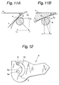
- FIGS. 11A and 11B are vector diagrams which illustrate a "lever action" in the prior lever type connector.
- FIG. 12 is a side elevational view of a prior lever, illustrating a shape of a cam groove.
- a female connector housing 1 accommodating female terminals is disposed over a male connector housing 2 accommodating male terminals.
- the female connector housing 1 is adapted to be inserted into the male connector housing 2.
- a lever 4 having a cam groove 3 which effects the "lever action” is rotatably attached to the male connector housing 2.
- a cover 5 to be put on the female connector housing 1 is provided with a cam follower boss 6.
- the cam groove 3 in the lever 4 is formed in a circular arc around a bearing bore 4a which is a rotation center of the lever 4. Opposite side end faces 3a and 3b in the cam groove 3 serve as cam faces.
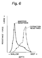
- a curved line indicating a change of an insertion resistance upon insertion of the female and male terminals forms a peak when the female connector housing 1 is disposed in a shallow position in the male connector housing 2 since a larger insertion resistance is generated at a primary insertion of the terminals.
- a larger extraction resistance is generated at a primary extraction of the terminals on account of a large stationary frictional force.
- a curved line indicating a change in the extraction resistance become a peak when the female connector housing 1 is disposed in a deep position in the male connector housing 2. This will be explained in more detail hereinafter.
- a connector which has, for example, two kinds of terminals provided for an electrical power source supply and a signal transmission in a single connector housing.
- the terminals for the electrical power supply are of a large size while the terminals for the signal transmission are of a small size.
- the large terminals for the electrical power supply being to interconnect and then the small terminals for the signal transmission begin to interconnect. Consequently changes in resistance upon insertion and extraction in connection with turning operation of the lever 4 become a simple curve with a peak in the prior connector having a single kind of terminal and become a complex curve with two peaks in the connector having two kinds of terminals. This will be described in more detail hereinafter.
- a first object of the present invention is to provide a lever type connector which can effectively generate a suitable force in response to a change of insertion and extraction of female and male terminals and can effect a turning operation of a lever by a smooth and light actuating force without making the lever large.
- a second object of the present invention is to provide a lever type connector which can generate a suitable force in response to a change of resistance upon coupling and detaching the connector even if the connector has a plurality of kinds of terminals and can effect a turning operation of a lever by a smooth and light actuating force.
- a lever is rotatably connected to one of connector housing to be coupled to each other, a cam follower boss is provided on the other of said connector housings, said boss is adapted to engage with a grooved cam formed in said lever, and said connector housings are coupled to and detached from each other by turning said lever so that said cam follower boss is displaced along a cam face on said grooved cam.
- a shape of said grooved cam on which said cam follower boss contacts upon coupling and detaching of said connector housings is formed by coupling and detaching resistances of said connector housings.
- the cam follower boss contacts with one cam face when the connector is coupled and it contacts with the other cam face when the connector is detached. Since the shapes of the cam faces are formed in accordance with the coupling and detaching resistances of the connector, a force most suitable for a change of resistance acts on the connector.
- the lever type connector of the present invention since a suitable force acts on the connector in response to a change of resistance upon coupling and detaching the connector, it is possible to effect the turning operation of the lever without making the lever large.
- a lever type connector of the present invention has more than two kinds of terminals in which timings of insertion and extraction in the female and male connector housings are different.
- the shape of the cam groove in the lever is discontinuously formed in connection with the insertion and extraction timings of a plurality of kinds of terminals.
- the shape of the cam groove in the lever is discontinuously formed in connection with the insertion and extraction timings of the kinds of terminals, discontinuous coupling and detaching forces according to the shape of cam groove can be obtained in connection with the insertion and extraction timings of the kinds of terminals upon coupling and detaching the connector.
- the lever type connector can generate discontinuous coupling and detaching forces according to the insertion and extraction timings of the terminals, thereby effecting the turning operation by a smooth and light force.
- FIGS. 1 to 9 embodiments of a lever type connector of the present invention will be explained below.
- FIGS. 1 to 6 show a first embodiment of the present invention.
- FIG. 5 shows a general construction of the lever type connector of the present invention.
- the connector includes a male connector housing 11 in which male terminals not shown are mounted and a female connector housing 12 in which female terminals not shown are mounted.
- the female connector housing 12 is provided on an upper portion with a cover 13 which covers the portion.
- the cover 13 engage with the female connector housing 12 by means of a lock mechanism 13a.
- the female connector housing 12 is provided on center portion of opposite side walls of the female connector housing 12 with cam follower bosses 17 which engage with cam grooves in a lever described hereinafter.
- the male connector housing 11 has a box like hood 18 which is open at an upper portion.
- the hood 18 is provided on opposite side walls with lever support shafts 19.
- the lever 14 has two legs 15 which are connected by a bridge member 14a at upper ends. Each leg 15 has a bearing bore 20 in which the lever support shafts 19.
- the shape of the cam groove 16 in the leg 15 of the lever 14 is shown in detail in FIG. 1.
- the cam groove 16 is formed into a circular arc around the bearing bore 20 in the leg 15 and is closed at an upper end by a thin boss guide 16C.
- the cam follower boss 17 on the cover 13 elastically deflects the leg 15 of the lever 14 and advances through the boss guide 16C into the cam groove 16.
- a left side end 16a in the cam groove 16 serves as a cam face upon coupling the connector while a right side end 16b serves as a cam face upon detaching the connector.
- FIG. 6 shows curves of insertion and extraction resistances of the terminals.
- the axis of abscissa indicates a depth of the female connector housing 12 in the male connector housing 11 and the axis of ordinate indicates a force.
- An insertion resistance upon inserting the terminals is changed from the left to the right as shown by a solid line while an extraction resistance upon extracting the terminals is changed from the right to the left as shown in one dotted chain line. Since a stationary frictional force becomes large upon extracting the terminals, a large extraction resistance is generated at upon initial detachment of the connector and a peak appears on a resistance curved when the female connector housing 12 is disposed in a deep position.
- the left side end 16a is different in shape from the light side end 16b.
- a width of the cam groove 16 alters along the groove on the contrary of the prior cam groove.
- the left side end 16a which serves as the cam face upon coupling the connector is shaped in accordance with the resistance curve of terminal insertion which has the peak in a shallow position as shown by the full line in FIG. 6.
- the right side end 16b which serves as the cam face upon detaching the connector is shaped in accordance with the resistance curve of terminal extraction which has the peak in a deep position as shown in one dotted chain line in FIG. 6.
- the left side end 16a which serves as the cam face upon coupling the connector is designed so that an inclination angle of the cam face is small in an area where an angle ⁇ is small (an area where the cam follower boss 17 contacts with at a beginning of insertion).
- the right side end 16b which serves as the cam face upon detaching the connector is designed so that the inclination angle of the cam face is small in an area where an angle ⁇ is large (an area where the cam follower boss 17 contacts with at a beginning of extraction).
- ⁇ is an angle between the straight lines Y and A.
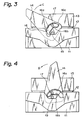
- the female connector housing 12 is inserted into the hood 18 of the male connector housing 11 and the lever 14 is turned to a direction shown by an arrow C in FIG. 3. Then, as shown in FIG. 3, the cam follower boss 17 which has advanced in the cam groove 16 is pushed down by the left side end 16a in the cam groove 16 so that the cover 13 and the female connector housing 12 move into the male connector housing 11. Then, the female and male terminals in the connector housings 11 and 12 are interconnected.
- the insertion resistance at this time inclines to show a peak shown in the solid line in FIG. 6 upon initial insertion of the female connector housing 12 (at a relatively shallow position of insertion).
- the inclination angle of the cam face is set to be small at an area where the angle ⁇ is small in the left side end 16a in the cam groove 16 (an area where the insertion position is relatively shallow) in this embodiment, a larger pushing-down force acts on the female connector housing 12 at the first half of a coupling operation. Consequently, it is possible to push down the female connector housing by a large force in accordance with the increased insertion resistance at the first half of the coupling operation, thereby causing the lever 14 to be turned by a smooth and light actuating force.
- the lever 14 is turned to a direction shown by an arrow D in FIG. 4 upon detaching the connector.
- the cam follower boss 17 is pushed down by the right side end 16b in the cam groove 16 and the cover 13 and the female connector housing 12 are detached from the hood 18.
- the female and male terminals are detached from each other.
- the extraction resistance inclines to show a peak under an initial detaching operation of the connector (at a deep position of the female connector 12 in the male connector housing 11) as shown by one dotted chain line in FIG. 6.
- the inclination angle of the cam face is set to be small at an area where the angle ⁇ is large in the right side end 16b in the cam groove 16 (an area where the insertion position is relatively deep), a larger pushing-up force acts on the female connector housing 12 at the first half of a detaching operation. Consequently, it is possible to push up the female connector housing 12 by a large force in accordance with the increased extraction resistance at the first half of the detaching operation, thereby turning the lever 14 by a smooth and light force.
- the cam faces 16a and 16b are shaped individually in accordance with the coupling and detaching of the connector, a force most suitable for a resistance change can act on the female connector housing 12. It is possible to turn the lever 14 by a smooth and light force upon coupling and detaching the connector.
- the present invention is not limited to the above embodiment and the lever may be attached to the female connector housing while the cam follower boss may be provided on the male connector housing.
- the present invention can be applied to a connector which is coupled and detached by utilizing the "lever action".
- the male connector housing 11 has a box like hood 18 which is opened at an upper portion.
- the hood 18 is provided in its interior with male terminals T p for an electrical power supply and male terminals T s for a signal transmission (see FIGS. 9A to 9C).
- the male terminals T p for the electrical power supply are larger and higher than the male terminals T s for the signal transmission.
- the shape of the cam groove 16 in the leg 15 of the lever 14 is shown in FIG. 8.
- the cam groove 16 is formed in the left side with respect to the bearing bore 20 in the leg in the drawing and closed at the thin guide portion 16C.
- the shape of the cam groove is set in accordance with a resistance change of terminal insertion shown in FIGS. 7A and 7B described hereinafter.
- the cam groove is formed into a curve having two circular arcs combined by a point of inflection and two peaks.
- the lever 14 In order to couple the connector, the lever 14 is turned to a direction shown by an arrow C in FIG. 8. Then, one of the side ends in the cam groove 16 pushes down the cam follower boss 17 so that the cover 13 and female connector housing 12 are inserted deeply in the hood 18. Consequently, the female and male terminals mounted in the connector housings are interconnected. At this time, however, since the male terminals T p for the electrical power supply are higher than the male terminals T s for the signal transmission, insertion begins from the terminals T p . Accordingly, an insertion resistance of the female and male terminals alters discontinuously as shown in FIG. 7A.
- the cam groove 16 is designed by the discontinuous curve combining two circular arcs in accordance with the insertion resistance of the terminals shown in FIG. 7A, the discontinuous forces are applied to the female connector housing 12 in response to the insertion timings of terminals T p and T s and thus the female connector housing 12 is pushed down in accordance with the discontinuous insertion resistance of the terminals. Consequently, even if there is any discontinuous insertion resistance of the terminals, the lever 14 can be turned by a smooth and light force.
- the lever 14 is turned to a reversed direction in FIG. 8. Then, since the cam follower boss 17 is pushed up by the other side end in the cam groove 16, the cover 13 and female connector housing 12 are moved from the hood 18, thereby extracting the female and male terminals. At this time, since two kinds of male terminals are provided in the second embodiment, the extraction resistance of the female and male terminals alter discontinuously in the same manner as the extraction resistance shown in FIG. 7B. However, in this case, the discontinuous force is applied to the female connector housing 12 due to the special shape of the cam groove 16 and the force accords with the discontinuous extraction resistance of the terminals, thereby turning the lever 14 by a smooth and light force.
- the shape of the cam groove 16 is formed discontinuously in accordance with the insertion and extraction timings of the terminals in view of the two kinds of timing of the terminals, the discontinuous coupling and detaching forces according to the timings can be applied to the female connector housing 12. Consequently, the lever 14 can be turned by a smooth and light force.
- the present invention is not limited to the above embodiments stated in the description and illustrated in the drawings and can be applied to any lever type connector having a plurality of terminals to be inserted and extracted in different timings.
Landscapes
- Details Of Connecting Devices For Male And Female Coupling (AREA)
Applications Claiming Priority (6)
| Application Number | Priority Date | Filing Date | Title |
|---|---|---|---|
| JP1700993 | 1993-01-06 | ||
| JP17010/93 | 1993-01-06 | ||
| JP1700993A JP2812124B2 (ja) | 1993-01-06 | 1993-01-06 | レバー式コネクタ |
| JP1701093 | 1993-01-06 | ||
| JP1701093A JP2900738B2 (ja) | 1993-01-06 | 1993-01-06 | レバー式コネクタ |
| JP17009/93 | 1993-01-06 |
Publications (3)
| Publication Number | Publication Date |
|---|---|
| EP0606152A2 true EP0606152A2 (fr) | 1994-07-13 |
| EP0606152A3 EP0606152A3 (fr) | 1995-06-28 |
| EP0606152B1 EP0606152B1 (fr) | 2000-03-15 |
Family
ID=26353467
Family Applications (1)
| Application Number | Title | Priority Date | Filing Date |
|---|---|---|---|
| EP94300036A Expired - Lifetime EP0606152B1 (fr) | 1993-01-06 | 1994-01-04 | Connecteur à levier de verrouillage |
Country Status (3)
| Country | Link |
|---|---|
| US (2) | US5518413A (fr) |
| EP (1) | EP0606152B1 (fr) |
| DE (1) | DE69423372T2 (fr) |
Cited By (12)
| Publication number | Priority date | Publication date | Assignee | Title |
|---|---|---|---|---|
| EP0722203A1 (fr) * | 1995-01-16 | 1996-07-17 | Molex Incorporated | Ensemble d'un connecteur électrique avec un système de came améliorée |
| US5672067A (en) * | 1995-01-10 | 1997-09-30 | The Whitaker Corporation | Electrical connector having a mating slide with customized camming slot |
| GB2327155A (en) * | 1997-06-28 | 1999-01-13 | Smiths Industries Plc | Lever-operated connector |
| US20140254993A1 (en) * | 2013-03-05 | 2014-09-11 | Finisar Corporation | Latch mechanism for communication module |
| US20160238812A1 (en) * | 2011-10-07 | 2016-08-18 | Commscope Technologies Llc | Slidable fiber optic connection module with cable slack management |
| CN108701939A (zh) * | 2016-01-29 | 2018-10-23 | 罗伯特·博世有限公司 | 电插塞连接部 |
| US10495833B2 (en) | 2012-09-21 | 2019-12-03 | Commscope Technologies Llc | Slidable fiber optic connection module with cable slack management |
| US10539757B2 (en) | 2016-04-19 | 2020-01-21 | Commscope, Inc. Of North Carolina | Telecommunications chassis with slidable trays |
| US11256054B2 (en) | 2018-04-16 | 2022-02-22 | Commscope Technologies Llc | Adapter structure |
| US11385429B2 (en) | 2017-10-18 | 2022-07-12 | Commscope Technologies Llc | Fiber optic connection cassette |
| US11674345B2 (en) | 2016-04-19 | 2023-06-13 | Commscope, Inc. Of North Carolina | Door assembly for a telecommunications chassis with a combination hinge structure |
| US11852882B2 (en) | 2018-02-28 | 2023-12-26 | Commscope Technologies Llc | Packaging assembly for telecommunications equipment |
Families Citing this family (16)
| Publication number | Priority date | Publication date | Assignee | Title |
|---|---|---|---|---|
| JP3341810B2 (ja) * | 1997-03-03 | 2002-11-05 | 矢崎総業株式会社 | Lifコネクタ |
| US6155860A (en) * | 1998-01-31 | 2000-12-05 | Berg Technology, Inc. | Socket for electrical component |
| US6406316B1 (en) | 1998-01-31 | 2002-06-18 | Fci Americas Technology, Inc. | Electrical connector with multiple housings |
| GB2334632B (en) * | 1998-02-23 | 2002-03-13 | Delphi Automotive Systems Gmbh | Two-part electrical connector |
| US5938458A (en) * | 1998-06-17 | 1999-08-17 | Molex Incorporated | Lever type electrical connector |
| EP1028494B1 (fr) * | 1999-02-12 | 2005-04-27 | The Whitaker Corporation | Ensemble de connecteur actionné par levier avec deux connecteurs complémentaires |
| JP3412562B2 (ja) * | 1999-06-14 | 2003-06-03 | 住友電装株式会社 | レバー式コネクタ |
| US6325648B1 (en) | 2001-02-07 | 2001-12-04 | Yazaki North America, Inc. | Electrical connector assembly with complementary lever assist and terminal delay |
| JP3783847B2 (ja) * | 2001-05-15 | 2006-06-07 | 住友電装株式会社 | 電線カバー |
| JP3882111B2 (ja) * | 2002-04-22 | 2007-02-14 | 住友電装株式会社 | レバー式コネクタ |
| US6648669B1 (en) | 2002-07-17 | 2003-11-18 | Yazaki North America | Electrical connection with sequential disconnect |
| JP2004311190A (ja) * | 2003-04-07 | 2004-11-04 | Sumitomo Wiring Syst Ltd | レバー式コネクタ |
| DE10332893A1 (de) * | 2003-07-19 | 2005-02-10 | Leopold Kostal Gmbh & Co Kg | Elektrischer Steckverbinder |
| US20060124698A1 (en) * | 2004-11-29 | 2006-06-15 | Hawthorne Jack W Jr | Device, and associated method, for coupling trusses together |
| US9368911B2 (en) * | 2014-11-14 | 2016-06-14 | GM Global Technology Operations LLC | Systems and methods for self-closing electrical connector |
| EP3059809B1 (fr) * | 2015-02-17 | 2018-06-06 | Advanced Digital Broadcast S.A. | Bouchon comportant un mécanisme de traction |
Family Cites Families (9)
| Publication number | Priority date | Publication date | Assignee | Title |
|---|---|---|---|---|
| DE3527916A1 (de) * | 1985-08-03 | 1987-02-12 | Cannon Electric Gmbh | Elektrische steckerkupplung |
| JPH0769759B2 (ja) * | 1988-09-08 | 1995-07-31 | 三菱電機株式会社 | メモリカード用接続機構 |
| US5135410A (en) * | 1990-05-30 | 1992-08-04 | Sumitomo Wiring Systems, Ltd. | Electric connector assembly |
| JP2971531B2 (ja) * | 1990-06-29 | 1999-11-08 | 住友電装株式会社 | コネクタの結合構造 |
| US5230635A (en) * | 1991-06-25 | 1993-07-27 | Yazaki Corporation | Connector with lever |
| JP2812015B2 (ja) * | 1991-10-21 | 1998-10-15 | 住友電装株式会社 | コネクタ |
| JP2598603Y2 (ja) * | 1992-08-19 | 1999-08-16 | 矢崎総業株式会社 | 低挿抜力コネクタ |
| JP2583261Y2 (ja) * | 1992-12-24 | 1998-10-22 | 住友電装株式会社 | レバー式コネクタ |
| JP2595864Y2 (ja) * | 1993-03-19 | 1999-06-02 | 住友電装株式会社 | レバー式コネクタ |
-
1994
- 1994-01-04 EP EP94300036A patent/EP0606152B1/fr not_active Expired - Lifetime
- 1994-01-04 DE DE69423372T patent/DE69423372T2/de not_active Expired - Lifetime
-
1995
- 1995-04-19 US US08/425,708 patent/US5518413A/en not_active Expired - Lifetime
- 1995-05-23 US US08/448,102 patent/US5531605A/en not_active Expired - Lifetime
Cited By (25)
| Publication number | Priority date | Publication date | Assignee | Title |
|---|---|---|---|---|
| US5672067A (en) * | 1995-01-10 | 1997-09-30 | The Whitaker Corporation | Electrical connector having a mating slide with customized camming slot |
| EP0722203A1 (fr) * | 1995-01-16 | 1996-07-17 | Molex Incorporated | Ensemble d'un connecteur électrique avec un système de came améliorée |
| GB2327155A (en) * | 1997-06-28 | 1999-01-13 | Smiths Industries Plc | Lever-operated connector |
| US10678010B2 (en) | 2011-10-07 | 2020-06-09 | Commscope Technologies Llc | Slidable fiber optic connection module with cable slack management |
| US11693203B2 (en) | 2011-10-07 | 2023-07-04 | Commscope Technologies Llc | Slidable fiber optic connection module with cable slack management |
| US20160238812A1 (en) * | 2011-10-07 | 2016-08-18 | Commscope Technologies Llc | Slidable fiber optic connection module with cable slack management |
| US9715075B2 (en) * | 2011-10-07 | 2017-07-25 | Commscope Technologies Llc | Slidable fiber optic connection module with cable slack management |
| US11022771B2 (en) | 2012-09-21 | 2021-06-01 | Commscope Technologies Llc | Slidable fiber optic connection module with cable slack management |
| US11585997B2 (en) | 2012-09-21 | 2023-02-21 | Commscope Technologies Llc | Slidable fiber optic connection module with cable slack management |
| US12481113B2 (en) | 2012-09-21 | 2025-11-25 | Commscope Technologies Llc | Slidable fiber optic connection module with cable slack management |
| US10495833B2 (en) | 2012-09-21 | 2019-12-03 | Commscope Technologies Llc | Slidable fiber optic connection module with cable slack management |
| US20140254993A1 (en) * | 2013-03-05 | 2014-09-11 | Finisar Corporation | Latch mechanism for communication module |
| US9423579B2 (en) * | 2013-03-05 | 2016-08-23 | Finisar Corporation | Latch mechanism for communication module |
| US10511124B2 (en) | 2016-01-29 | 2019-12-17 | Robert Bosch Gmbh | Electrical plug connection |
| CN108701939A (zh) * | 2016-01-29 | 2018-10-23 | 罗伯特·博世有限公司 | 电插塞连接部 |
| US11674345B2 (en) | 2016-04-19 | 2023-06-13 | Commscope, Inc. Of North Carolina | Door assembly for a telecommunications chassis with a combination hinge structure |
| US11042001B2 (en) | 2016-04-19 | 2021-06-22 | Commscope, Inc. Of North Carolina | Telecommunications chassis with slidable trays |
| US11585996B2 (en) | 2016-04-19 | 2023-02-21 | Commscope, Inc. Of North Carolina | Telecommunications chassis with slidable trays |
| US10539757B2 (en) | 2016-04-19 | 2020-01-21 | Commscope, Inc. Of North Carolina | Telecommunications chassis with slidable trays |
| US11782230B2 (en) | 2017-10-18 | 2023-10-10 | Commscope Technologies Llc | Fiber optic connection cassette |
| US11385429B2 (en) | 2017-10-18 | 2022-07-12 | Commscope Technologies Llc | Fiber optic connection cassette |
| US11852882B2 (en) | 2018-02-28 | 2023-12-26 | Commscope Technologies Llc | Packaging assembly for telecommunications equipment |
| US11635580B2 (en) | 2018-04-16 | 2023-04-25 | Commscope Technologies Llc | Adapter structure |
| US12055778B2 (en) | 2018-04-16 | 2024-08-06 | Commscope Technologies Llc | Adapter structure |
| US11256054B2 (en) | 2018-04-16 | 2022-02-22 | Commscope Technologies Llc | Adapter structure |
Also Published As
| Publication number | Publication date |
|---|---|
| DE69423372D1 (de) | 2000-04-20 |
| US5518413A (en) | 1996-05-21 |
| EP0606152A3 (fr) | 1995-06-28 |
| EP0606152B1 (fr) | 2000-03-15 |
| US5531605A (en) | 1996-07-02 |
| DE69423372T2 (de) | 2000-10-26 |
Similar Documents
| Publication | Publication Date | Title |
|---|---|---|
| US5518413A (en) | Lever type connector | |
| US6921274B2 (en) | Electrical connector with improved contact | |
| US6019620A (en) | Device having engaging levers for connecting electrical members | |
| KR100220352B1 (ko) | 개선된 캠 장치를 갖춘 전기 커넥터 조립체 | |
| EP1211752B1 (fr) | Connecteur électrique du type à faible force d'insertion | |
| EP0966067A3 (fr) | Connecteur à levier de verrouillage | |
| KR100916384B1 (ko) | 커넥터 | |
| KR950026055A (ko) | 전기 커넥터 | |
| EP0991145A3 (fr) | Connecteur électrique en deux parties | |
| EP1005112A3 (fr) | Connecteur électrique | |
| EP0938162A3 (fr) | Connecteur électrique en deux parties | |
| EP1137120A3 (fr) | Connecteur électrique à levier de verrouillage | |
| EP0603891B1 (fr) | Connecteur ayant un levier | |
| GB2260659A (en) | Lever for operating an electrical connector | |
| JP2004158206A (ja) | 平形柔軟ケーブル用電気コネクタ | |
| US5584721A (en) | Connector | |
| US6234828B1 (en) | Electrical connector assembly with improved locking means | |
| EP0579428B1 (fr) | Connecteur à levier de verrouillage | |
| US6648659B2 (en) | Lever-type connector and a method for mounting a lever-type connector into a hole of a panel | |
| JP2897110B2 (ja) | カムレバーロック機構を有する電気コネクタアッセンブリ | |
| US5957710A (en) | Lif connector | |
| US5733144A (en) | Electrical connector with flexible retaining piece | |
| GB2271029A (en) | Electric connector lever arrangement | |
| US6164992A (en) | Structure of lever of lever engagement type connector | |
| US5975930A (en) | Slide fit connector |
Legal Events
| Date | Code | Title | Description |
|---|---|---|---|
| PUAI | Public reference made under article 153(3) epc to a published international application that has entered the european phase |
Free format text: ORIGINAL CODE: 0009012 |
|
| AK | Designated contracting states |
Kind code of ref document: A2 Designated state(s): DE GB |
|
| PUAL | Search report despatched |
Free format text: ORIGINAL CODE: 0009013 |
|
| AK | Designated contracting states |
Kind code of ref document: A3 Designated state(s): DE GB |
|
| 17P | Request for examination filed |
Effective date: 19951215 |
|
| 17Q | First examination report despatched |
Effective date: 19981112 |
|
| GRAG | Despatch of communication of intention to grant |
Free format text: ORIGINAL CODE: EPIDOS AGRA |
|
| GRAG | Despatch of communication of intention to grant |
Free format text: ORIGINAL CODE: EPIDOS AGRA |
|
| GRAH | Despatch of communication of intention to grant a patent |
Free format text: ORIGINAL CODE: EPIDOS IGRA |
|
| GRAH | Despatch of communication of intention to grant a patent |
Free format text: ORIGINAL CODE: EPIDOS IGRA |
|
| GRAA | (expected) grant |
Free format text: ORIGINAL CODE: 0009210 |
|
| AK | Designated contracting states |
Kind code of ref document: B1 Designated state(s): DE GB |
|
| REF | Corresponds to: |
Ref document number: 69423372 Country of ref document: DE Date of ref document: 20000420 |
|
| EN | Fr: translation not filed | ||
| PLBE | No opposition filed within time limit |
Free format text: ORIGINAL CODE: 0009261 |
|
| STAA | Information on the status of an ep patent application or granted ep patent |
Free format text: STATUS: NO OPPOSITION FILED WITHIN TIME LIMIT |
|
| 26N | No opposition filed | ||
| REG | Reference to a national code |
Ref country code: GB Ref legal event code: IF02 |
|
| PGFP | Annual fee paid to national office [announced via postgrant information from national office to epo] |
Ref country code: DE Payment date: 20130103 Year of fee payment: 20 Ref country code: GB Payment date: 20130102 Year of fee payment: 20 |
|
| REG | Reference to a national code |
Ref country code: DE Ref legal event code: R071 Ref document number: 69423372 Country of ref document: DE |
|
| REG | Reference to a national code |
Ref country code: GB Ref legal event code: PE20 Expiry date: 20140103 |
|
| PG25 | Lapsed in a contracting state [announced via postgrant information from national office to epo] |
Ref country code: GB Free format text: LAPSE BECAUSE OF EXPIRATION OF PROTECTION Effective date: 20140103 Ref country code: DE Free format text: LAPSE BECAUSE OF EXPIRATION OF PROTECTION Effective date: 20140108 |