EP0606409B1 - Überspannungsschutz - Google Patents
Überspannungsschutz Download PDFInfo
- Publication number
- EP0606409B1 EP0606409B1 EP93906332A EP93906332A EP0606409B1 EP 0606409 B1 EP0606409 B1 EP 0606409B1 EP 93906332 A EP93906332 A EP 93906332A EP 93906332 A EP93906332 A EP 93906332A EP 0606409 B1 EP0606409 B1 EP 0606409B1
- Authority
- EP
- European Patent Office
- Prior art keywords
- tube
- arrester
- stack
- surge arrester
- elements
- Prior art date
- Legal status (The legal status is an assumption and is not a legal conclusion. Google has not performed a legal analysis and makes no representation as to the accuracy of the status listed.)
- Expired - Lifetime
Links
Images
Classifications
-
- H—ELECTRICITY
- H01—ELECTRIC ELEMENTS
- H01C—RESISTORS
- H01C7/00—Non-adjustable resistors formed as one or more layers or coatings; Non-adjustable resistors made from powdered conducting material or powdered semi-conducting material with or without insulating material
- H01C7/10—Non-adjustable resistors formed as one or more layers or coatings; Non-adjustable resistors made from powdered conducting material or powdered semi-conducting material with or without insulating material voltage responsive, i.e. varistors
- H01C7/12—Overvoltage protection resistors; Arresters
- H01C7/126—Means for protecting against excessive pressure or for disconnecting in case of failure
-
- H—ELECTRICITY
- H01—ELECTRIC ELEMENTS
- H01C—RESISTORS
- H01C7/00—Non-adjustable resistors formed as one or more layers or coatings; Non-adjustable resistors made from powdered conducting material or powdered semi-conducting material with or without insulating material
- H01C7/10—Non-adjustable resistors formed as one or more layers or coatings; Non-adjustable resistors made from powdered conducting material or powdered semi-conducting material with or without insulating material voltage responsive, i.e. varistors
- H01C7/12—Overvoltage protection resistors; Arresters
Definitions
- the present invention relates to a surge arrester comprising a stack of a plurality of cylindrical arrester elements which are preferably made of metal oxide varistor material and which are arranged one after the other in the axial direction of the arrester elements between two end electrodes and surrounded by an elongated outer casing.
- the outer casing of currently used surge arresters is usually made of porcelain.
- a porcelain casing has good electrical insulating properties and also has sufficient mechanical strength to take up, inter alia, the axially directed compressive force on the arrester elements, which is generated by springs and which is required to obtain good electrical contact between the elements.
- some form of overpressure relief arrangement is required to avoid an explosion-like failure, if, for example in the event of a fault on an arrester element, a short-circuit arc is formed inside the arrester with an ensuing pressure increase.
- this surge arrester is provided with an overpressure relief arrangement of, in principle, the same type as that used in connection with surge arresters with a porcelain casing.
- the object of the present invention is to obtain a surge arrester which is provided with polymer casing and which does not suffer from the above-mentioned drawbacks.
- This is achieved according to the invention by using, for mechanical reinforcement of the polymer casing, a fibre-reinforced plastic tube which is made by profile drawing, so-called pultrusion, whereby all reinforcement fibres extend in the axial direction of the tube.
- a pultruded fibre-reinforced tube has a very high tensile strength.
- the required bending strength is obtained by choosing a suitable wall thickness and amount and type of reinforcement fibres.
- a relatively low strength in the radial direction is obtained. This permits a favourable failure process since the tube easily cracks up also at low short-circuit currents.
- pultruded tubes are very cost-effective.
- the surge arrester shown in the figure is primarily intended for use in distribution networks with operating voltages of up to about 40 kV. However, the same design principle may be used to advantage also in surge arresters for operating voltages of the order of magnitude of 100 kV and higher.
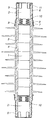
- the arrester shown comprises a stack of arrester elements 1 in the form of circular-cylindrical ZnO blocks, possibly with heat-absorbing spacers of metal, and an end electrode 2 in the form of a metal pellet at each end of the stack.
- the end electrodes 2 and the spacers, if any, may suitably be made of aluminium.
- the entire stack of ZnO blocks 1, end electrodes 2 and spacers, if any, is arranged in an elongated tube 4 of glassfibre-reinforced plastic, which in turn is surrounded by an insulating casing 3 made of polymeric material.
- the stack is axially fixed to the tube 4 by means of metal cases 5, which surround the end portions of the tube 4 and are fixed to the tube by pressing the cylindrical mantle part of the respective case into annular slots 6 in the tube.
- the figure shows, on opposite sides of the centre line of the surge arrester, the metal case 5 before and after the pressing of the mantle part into the annular slots.
- the metal cases 5 are formed with a collar 7, which surrounds the respective end portion of the polymer insulator 3 and is fixed to the insulator by a surrounding indentation 8. Between the metal collar 7 and the insulator 3 there is a seal 9, for example in the form of an O-ring.
- the pressing of the metal cases 5 onto the plastic tube 4, in certain types of plastic material, may be performed without the tube being provided in advance with the surrounding slots 6.
- the slots in the plastic material are formed directly in connection with the pressing of the metal cases.
- a spring device in the form of a disc spring assembly 10 is arranged near the end electrodes.
- the end electrodes 2 are provided with threaded fixing holes 11 for connection members.
- the tube 4 is a glassfibre-reinforced tube of plastic material, for example polyester, polyvinyl ester, epoxy or a thermoplastic resin.
- the tube is made by profile drawing, so-called pultrusion. This is a method of production for fibre composites in which the raw materials included are continuously and automatically directly converted into a finished product. In tubes manufactured according to this method, all reinforcement fibres are arranged axially. This gives the tube very special properties, of which a high tensile strength in combination with a low strength in the radial direction are particularly important properties for the present invention. Tubes of this type are available on the market.
- the outer insulating casing 3 may be an elastomer, for example an ethylene-propylene-terpolymer (EPDM rubber) which is fitted over the tube 4. It may also consist of shrinking plastic, for example a crosslinked ethylene-propylene polymer or crosslinked HD-polyethylene which is applied to the tube 4 by shrinking.
- the insulating casing 3 may also be formed directly on the tube 4 by casting or injection moulding.
- the gap between the stack and the tube may be filled with an electrically insulating compound, for example epoxy or silicone compound.
- the tube 4 may consist of a shrinkable plastic material and be applied on the ZnO stack by shrinkage.
- ZnO blocks are usually manufactured in a number of different transverse dimensions (diameters) to make it possible to build surge arresters for different current ranges in an economical way.
- a surge arrester according to the present invention it may be an advantage from the manufacturing point of view if the pultruded tube 4 can be manufactured with one and the same outside diameter for all sizes of ZnO blocks. Tubes which are intended for the smaller blocks are thereby provided internally with a number of longitudinal bars for centering the blocks, the spaces between the bars then being filled with silicone compound or the like.
- the tube 4 will burst in the longitudinal direction in a controlled manner at a relatively low internal overpressure. The risk of explosion causing personal danger is thereby eliminated.
Landscapes
- Engineering & Computer Science (AREA)
- Microelectronics & Electronic Packaging (AREA)
- Physics & Mathematics (AREA)
- Electromagnetism (AREA)
- Thermistors And Varistors (AREA)
- Insulators (AREA)
Claims (6)
- Überspannungsableiter mit einem Stapel aus einer Vielzahl von zylindrischen Ableiterelementen (1), die vorzugsweise aus Metalloxyd-Varistor-Material hergestellt sind und die in axialer Richtung der Ableiterelemente hintereinander zwischen zwei Endelektroden (2) angeordnet sind und von einem langgestreckten äußeren Gehäuse (3) umgeben sind, welches aus isolierendem Polymermaterial besteht, wobei zur mechanischen Verstärkung ein Rohr (4) aus faserverstärktem Kunststoff zwischen dem Stapel aus Ableiterelementen (1) und dem Isoliergehäuse (3) aus Polymer angeordnet ist, dadurch gekennzeichnet, daß das faserverstärkte Kunststoffrohr (4) durch Zieh-Strangpressen, sogenannte Pultrusion, hergestellt ist, wobei alle Verstärkungsfasern sich in axialer Richtung des Rohres (4) erstrecken.
- Überspannungsableiter nach Anspruch 1, dadurch gekennzeichnet, daß das äußere Isoliergehäuse (3) durch Aufschrumpfen auf dem faserverstärkten Kunststoffrohr (4) aufgebracht ist.
- Überspannungsableiter nach Anspruch 1, dadurch gekennzeichnet, daß das äußere Isoliergehäuse (3) auf dem faserverstärkten Kunststoffrohr (4) durch direktes Anformen an dem Rohr mittels Spritzgießen oder Gießen aufgebracht ist.
- Überspannungsableiter nach einem der Ansprüche 1 bis 3, dadurch gekennzeichnet, daß zwischen dem Kunststoffrohr (4) und dem Stapel aus Ableiterelementen (1) ein Spalt vorhanden ist, der mit einer isolierenden Masse, zum Beispiel einer Epoxi- oder Siliconmasse, ausgefüllt ist.
- Überspannungsableiter nach einem der Ansprüche 1 bis 3, dadurch gekennzeichnet, daß das Kunststoffrohr (4) durch Aufschrumpfen auf dem Stapel aus Ableiterelementen (1) aufgebracht ist.
- Überspannungsableiter nach einem der Ansprüche 1 bis 4, dadurch gekennzeichnet, daß das Kunststoffrohr (4) innen mit einer Anzahl Längsstege zur Zentrierung der Ableiterelemente (1) versehen ist, wobei die Zwischenräume zwischen den Stegen mit einer isolierenden Masse, zum Beispiel einer Siliconmasse, ausgefüllt sind.
Applications Claiming Priority (3)
| Application Number | Priority Date | Filing Date | Title |
|---|---|---|---|
| SE9102881A SE469247B (sv) | 1991-10-04 | 1991-10-04 | Ventilavledare |
| SE9102881 | 1991-10-04 | ||
| PCT/SE1992/000667 WO1993007630A1 (en) | 1991-10-04 | 1992-09-25 | Surge arrester |
Publications (2)
| Publication Number | Publication Date |
|---|---|
| EP0606409A1 EP0606409A1 (de) | 1994-07-20 |
| EP0606409B1 true EP0606409B1 (de) | 1995-12-13 |
Family
ID=20383906
Family Applications (1)
| Application Number | Title | Priority Date | Filing Date |
|---|---|---|---|
| EP93906332A Expired - Lifetime EP0606409B1 (de) | 1991-10-04 | 1992-09-25 | Überspannungsschutz |
Country Status (5)
| Country | Link |
|---|---|
| EP (1) | EP0606409B1 (de) |
| AU (1) | AU2750192A (de) |
| DE (1) | DE69206812T2 (de) |
| SE (1) | SE469247B (de) |
| WO (1) | WO1993007630A1 (de) |
Cited By (1)
| Publication number | Priority date | Publication date | Assignee | Title |
|---|---|---|---|---|
| EP1436819A4 (de) * | 2001-08-29 | 2008-11-05 | Cooper Technologies Co | Mechanische verstärkung zur verbesserung der wiederstandsfähigkeit einer monolithischen platte oder eines gebondeten plattenstapels gegenüber hohen strömen kurzer dauer |
Families Citing this family (9)
| Publication number | Priority date | Publication date | Assignee | Title |
|---|---|---|---|---|
| HUT69281A (en) * | 1993-10-13 | 1995-09-28 | Furukawa Electric Technologiai | Monolith lightning arrester of high tensile stress |
| JP3256436B2 (ja) * | 1996-06-03 | 2002-02-12 | 株式会社日立製作所 | 碍子型避雷器 |
| RU2144712C1 (ru) * | 1998-01-06 | 2000-01-20 | АООТ "НИИ Электрокерамика" | Устройство для защиты от перенапряжений |
| JP2001023807A (ja) * | 1999-07-09 | 2001-01-26 | Toshiba Corp | 避雷器およびその製造方法 |
| RU2203514C2 (ru) * | 1999-08-24 | 2003-04-27 | ЗАО "МСМ-трейдинг" | Изолятор, ограничитель перенапряжений и способ изготовления полимерной оболочки |
| ES2166689B1 (es) * | 2000-01-26 | 2003-10-16 | Ind De Aparellaje Electrico S | Descargador de sobretensiones. |
| DE102008050487A1 (de) | 2008-10-01 | 2010-04-15 | Siemens Aktiengesellschaft | Elektrische Vorrichtung mit einem Haltegerüst |
| RU2633996C1 (ru) * | 2016-07-11 | 2017-10-23 | Федеральное государственное бюджетное общеобразовательное учреждение высшего образования Липецкий государственный технический университет (ЛГТУ) | Устройство ограничения перенапряжения |
| RU180982U1 (ru) * | 2018-04-09 | 2018-07-03 | Закрытое Акционерное Общество "Полимер-Аппарат" | Нелинейный ограничитель перенапряжений |
Family Cites Families (2)
| Publication number | Priority date | Publication date | Assignee | Title |
|---|---|---|---|---|
| US4404614A (en) * | 1981-05-15 | 1983-09-13 | Electric Power Research Institute, Inc. | Surge arrester having a non-fragmenting outer housing |
| CA1334990C (en) * | 1988-03-31 | 1995-03-28 | John D. Sakich | Modular electrical assemblies with pressure relief |
-
1991
- 1991-10-04 SE SE9102881A patent/SE469247B/sv not_active IP Right Cessation
-
1992
- 1992-09-25 AU AU27501/92A patent/AU2750192A/en not_active Abandoned
- 1992-09-25 EP EP93906332A patent/EP0606409B1/de not_active Expired - Lifetime
- 1992-09-25 WO PCT/SE1992/000667 patent/WO1993007630A1/en not_active Ceased
- 1992-09-25 DE DE69206812T patent/DE69206812T2/de not_active Expired - Fee Related
Cited By (1)
| Publication number | Priority date | Publication date | Assignee | Title |
|---|---|---|---|---|
| EP1436819A4 (de) * | 2001-08-29 | 2008-11-05 | Cooper Technologies Co | Mechanische verstärkung zur verbesserung der wiederstandsfähigkeit einer monolithischen platte oder eines gebondeten plattenstapels gegenüber hohen strömen kurzer dauer |
Also Published As
| Publication number | Publication date |
|---|---|
| SE9102881D0 (sv) | 1991-10-04 |
| DE69206812D1 (de) | 1996-01-25 |
| SE469247B (sv) | 1993-06-07 |
| WO1993007630A1 (en) | 1993-04-15 |
| DE69206812T2 (de) | 1997-02-06 |
| AU2750192A (en) | 1993-05-03 |
| SE9102881L (sv) | 1993-04-05 |
| EP0606409A1 (de) | 1994-07-20 |
Similar Documents
| Publication | Publication Date | Title |
|---|---|---|
| US5363266A (en) | Electrical surge arrester | |
| CN1145248C (zh) | 电涌放电器 | |
| CA2009424C (en) | Electrical surge arrester/diverter | |
| US5043838A (en) | Modular electrical assemblies with pressure relief | |
| KR100211742B1 (ko) | 견고한 절연하우징을 가진 피뢰기 및 그 제조방법 | |
| US5497138A (en) | Varistor surge arrestors, in particular for high tension | |
| US4962440A (en) | Surge arrester | |
| US11177058B2 (en) | Composite surge arrester module in a die and method of construction | |
| US4905118A (en) | Base mounted electrical assembly | |
| US6008975A (en) | Self-compressive surge arrester module and method of making same | |
| JPH0410721B2 (de) | ||
| EP0606409B1 (de) | Überspannungsschutz | |
| EP0335480A2 (de) | Elektrische Modulareinheiten mit Druckentlastung | |
| AU713453B2 (en) | Overvoltage suppressor | |
| JP4327250B2 (ja) | 自己圧縮性サージ避雷器モジュール及びその製造方法 | |
| EP0304690A1 (de) | Herstellungsverfahren eines Blitzableiters und Blitzableiter nach diesem Verfahren hergestellt | |
| US5570264A (en) | Surge arrester | |
| CN1781164A (zh) | 一种电涌放电器 | |
| EP0372106B1 (de) | Überspannungsbegrenzer | |
| GB2258352A (en) | Overvoltage arrester | |
| WO1999007053A1 (en) | End terminals for modular electrical assemblies with pressure relief | |
| US5684665A (en) | Modular electrical assembly with conductive strips | |
| EP4369358A1 (de) | Überspannungsableitermodul und überspannungsableiter | |
| JP3448329B2 (ja) | 避雷装置 | |
| CA2247928C (en) | Self-compressive surge arrester module and method of making same |
Legal Events
| Date | Code | Title | Description |
|---|---|---|---|
| PUAI | Public reference made under article 153(3) epc to a published international application that has entered the european phase |
Free format text: ORIGINAL CODE: 0009012 |
|
| 17P | Request for examination filed |
Effective date: 19940331 |
|
| AK | Designated contracting states |
Kind code of ref document: A1 Designated state(s): DE FR IT |
|
| 17Q | First examination report despatched |
Effective date: 19950110 |
|
| GRAA | (expected) grant |
Free format text: ORIGINAL CODE: 0009210 |
|
| AK | Designated contracting states |
Kind code of ref document: B1 Designated state(s): DE FR IT |
|
| REF | Corresponds to: |
Ref document number: 69206812 Country of ref document: DE Date of ref document: 19960125 |
|
| ITF | It: translation for a ep patent filed | ||
| ET | Fr: translation filed | ||
| PLBE | No opposition filed within time limit |
Free format text: ORIGINAL CODE: 0009261 |
|
| STAA | Information on the status of an ep patent application or granted ep patent |
Free format text: STATUS: NO OPPOSITION FILED WITHIN TIME LIMIT |
|
| 26N | No opposition filed | ||
| PGFP | Annual fee paid to national office [announced via postgrant information from national office to epo] |
Ref country code: FR Payment date: 19980909 Year of fee payment: 7 |
|
| PGFP | Annual fee paid to national office [announced via postgrant information from national office to epo] |
Ref country code: DE Payment date: 19981005 Year of fee payment: 7 |
|
| PG25 | Lapsed in a contracting state [announced via postgrant information from national office to epo] |
Ref country code: FR Free format text: LAPSE BECAUSE OF NON-PAYMENT OF DUE FEES Effective date: 20000531 |
|
| PG25 | Lapsed in a contracting state [announced via postgrant information from national office to epo] |
Ref country code: DE Free format text: LAPSE BECAUSE OF NON-PAYMENT OF DUE FEES Effective date: 20000701 |
|
| REG | Reference to a national code |
Ref country code: FR Ref legal event code: ST |
|
| PG25 | Lapsed in a contracting state [announced via postgrant information from national office to epo] |
Ref country code: IT Free format text: LAPSE BECAUSE OF NON-PAYMENT OF DUE FEES;WARNING: LAPSES OF ITALIAN PATENTS WITH EFFECTIVE DATE BEFORE 2007 MAY HAVE OCCURRED AT ANY TIME BEFORE 2007. THE CORRECT EFFECTIVE DATE MAY BE DIFFERENT FROM THE ONE RECORDED. Effective date: 20050925 |