EP0606511B1 - Warnvorrichtung und -anlage für Reifenunterdruck und speziell dafür ausgebildetes Rad - Google Patents
Warnvorrichtung und -anlage für Reifenunterdruck und speziell dafür ausgebildetes Rad Download PDFInfo
- Publication number
- EP0606511B1 EP0606511B1 EP93100542A EP93100542A EP0606511B1 EP 0606511 B1 EP0606511 B1 EP 0606511B1 EP 93100542 A EP93100542 A EP 93100542A EP 93100542 A EP93100542 A EP 93100542A EP 0606511 B1 EP0606511 B1 EP 0606511B1
- Authority
- EP
- European Patent Office
- Prior art keywords
- inflation
- tyre
- centrifugal mass
- warning
- pressure
- Prior art date
- Legal status (The legal status is an assumption and is not a legal conclusion. Google has not performed a legal analysis and makes no representation as to the accuracy of the status listed.)
- Expired - Lifetime
Links
- 239000012528 membrane Substances 0.000 claims description 16
- 230000000903 blocking effect Effects 0.000 claims description 15
- 230000005484 gravity Effects 0.000 claims description 11
- 238000006073 displacement reaction Methods 0.000 claims description 4
- 208000031968 Cadaver Diseases 0.000 description 10
- 238000005259 measurement Methods 0.000 description 5
- 239000000725 suspension Substances 0.000 description 5
- 241001080024 Telles Species 0.000 description 4
- 230000007423 decrease Effects 0.000 description 4
- 230000000007 visual effect Effects 0.000 description 4
- 238000005096 rolling process Methods 0.000 description 3
- 238000012550 audit Methods 0.000 description 2
- 238000009434 installation Methods 0.000 description 2
- 230000035945 sensitivity Effects 0.000 description 2
- 238000004026 adhesive bonding Methods 0.000 description 1
- 230000005540 biological transmission Effects 0.000 description 1
- 238000009530 blood pressure measurement Methods 0.000 description 1
- 238000009529 body temperature measurement Methods 0.000 description 1
- 238000004891 communication Methods 0.000 description 1
- 238000013461 design Methods 0.000 description 1
- 238000001514 detection method Methods 0.000 description 1
- 238000010586 diagram Methods 0.000 description 1
- 238000003780 insertion Methods 0.000 description 1
- 230000037431 insertion Effects 0.000 description 1
- 239000000463 material Substances 0.000 description 1
- 238000012806 monitoring device Methods 0.000 description 1
Images



Classifications
-
- F—MECHANICAL ENGINEERING; LIGHTING; HEATING; WEAPONS; BLASTING
- F16—ENGINEERING ELEMENTS AND UNITS; GENERAL MEASURES FOR PRODUCING AND MAINTAINING EFFECTIVE FUNCTIONING OF MACHINES OR INSTALLATIONS; THERMAL INSULATION IN GENERAL
- F16F—SPRINGS; SHOCK-ABSORBERS; MEANS FOR DAMPING VIBRATION
- F16F7/00—Vibration-dampers; Shock-absorbers
- F16F7/10—Vibration-dampers; Shock-absorbers using inertia effect
- F16F7/1005—Vibration-dampers; Shock-absorbers using inertia effect characterised by active control of the mass
- F16F7/1017—Vibration-dampers; Shock-absorbers using inertia effect characterised by active control of the mass by fluid means
-
- B—PERFORMING OPERATIONS; TRANSPORTING
- B60—VEHICLES IN GENERAL
- B60C—VEHICLE TYRES; TYRE INFLATION; TYRE CHANGING; CONNECTING VALVES TO INFLATABLE ELASTIC BODIES IN GENERAL; DEVICES OR ARRANGEMENTS RELATED TO TYRES
- B60C23/00—Devices for measuring, signalling, controlling, or distributing tyre pressure or temperature, specially adapted for mounting on vehicles; Arrangement of tyre inflating devices on vehicles, e.g. of pumps or of tanks; Tyre cooling arrangements
- B60C23/02—Signalling devices actuated by tyre pressure
- B60C23/04—Signalling devices actuated by tyre pressure mounted on the wheel or tyre
-
- B—PERFORMING OPERATIONS; TRANSPORTING
- B60—VEHICLES IN GENERAL
- B60G—VEHICLE SUSPENSION ARRANGEMENTS
- B60G2200/00—Indexing codes relating to suspension types
- B60G2200/10—Independent suspensions
- B60G2200/14—Independent suspensions with lateral arms
- B60G2200/144—Independent suspensions with lateral arms with two lateral arms forming a parallelogram
-
- B—PERFORMING OPERATIONS; TRANSPORTING
- B60—VEHICLES IN GENERAL
- B60G—VEHICLE SUSPENSION ARRANGEMENTS
- B60G2202/00—Indexing codes relating to the type of spring, damper or actuator
- B60G2202/20—Type of damper
- B60G2202/25—Dynamic damper
-
- B—PERFORMING OPERATIONS; TRANSPORTING
- B60—VEHICLES IN GENERAL
- B60G—VEHICLE SUSPENSION ARRANGEMENTS
- B60G2206/00—Indexing codes related to the manufacturing of suspensions: constructional features, the materials used, procedures or tools
- B60G2206/01—Constructional features of suspension elements, e.g. arms, dampers, springs
- B60G2206/50—Constructional features of wheel supports or knuckles, e.g. steering knuckles, spindle attachments
Definitions
- the invention relates to tire monitoring devices. More particularly, it relates to a device, simple and inexpensive, warning of under-inflation of a tire.
- the object of the invention is to remedy the drawbacks indicated above by means of a device for warning of under-inflation of a tire which does not require the transmission of measurement signals between the wheel and the chassis of the vehicle, while offering great sensitivity.
- the subject of the invention is a device for warning of under-inflation of a tire, simple, inexpensive and easily adaptable to all current motor vehicles.
- This device to be mounted on the tire wheel, is characterized in that it creates an imbalance at the level of said wheel, when the inflation pressure of said tire is below a given threshold.
- this device is characterized in that it comprises means for off-centering a moving mass when the inflation pressure is below a given threshold.
- An improvement to the previous embodiment of the invention is characterized in that the device for warning of under-inflation of a tire comprises means for limiting the inflation pressure of said tire, during inflation.
- the means for limiting the inflation pressure, during inflation is characterized in that the blocking piece of the movable mass comes to rest on the end of a rod, the other end of which ends in a needle. closing of the inflating air supply duct of the tire, and thus blocks said duct when the inflation pressure reaches the nominal pressure of said tire.
- This improvement makes it possible to ensure inflation at the nominal pressure of the safe and simple tire.
- a second improvement to the embodiment of the preceding invention is characterized in that it includes a means of alerting the release of the mobile mass.
- the advantage of this improvement is that it makes it possible to warn, when stationary, the driver of the vehicle of the under-inflation of one of his tires by a simple visual examination of the device or by an interior alarm depending on the nature. , known per se, of the chosen means of alert.
- any of the preceding devices warning of under-inflation of a tire on the wheel disc of said tire is characterized in that, the moving mass being in the locked position, the center of gravity of said device is placed on the 'axis of the wheel of said tire.
- This second embodiment has the advantage of being mechanically simpler and easier to install on a wheel than the previous one.
- a final feature of the invention is the use of any one of the preceding devices in combination with a vibration sensor placed on the wheel carrier of the wheel of said tire.
- “Wheel carrier” means the part which actually carries the wheel without any other decoupling than the rolling rotation of the wheel.
- the under-inflation warning system thus formed is simple, inexpensive, highly sensitive and reliable. Indeed, the sudden appearance of a dynamic imbalance when the inflation pressure decreases below a given threshold is easily detected by the vibration sensor. This system thus overcomes the complexity of the evolution of the vibratory behavior of the wheel with the variation of the inflation pressure.
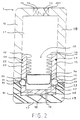
- the under-inflation warning device 1 comprises a fixed body 10, a mobile mass 20 and a locking means 30 for said mobile mass 20.
- the fixed cylindrical body 10 comprises an internal cavity in which the mobile mass 20 moves.
- This mobile mass 20 separates said internal cavity into two chambers 11 and 12.
- the chamber 11 is pneumatically connected to the tire via the conduit 13, it is therefore pressurized at the inflation pressure of said tire.
- the chamber 12 is connected to the atmosphere by the conduit 16, its internal pressure is therefore permanently atmospheric pressure.
- the device 1 can optionally be used to inflate the tire.
- the chamber 11 comprises a second conduit 14 equipped with a non-return valve 15 opposing the deflation of the tire.
- the pneumatic connection between the device 1 and the tire can be fitted with a non-return valve 131.
- This valve 131 is placed at any point of said connection for example at the level of the duct 13 as in FIGS. 1 to 4. However, it is preferably placed at the level of the valve of the rim of said tire.
- the fixed body 10 is made in two parts 18 and 19 assembled by gluing after the insertion of the movable mass 20 and the locking means 30.
- the choice of materials for these two parts 18 and 19 is such that, when the movable mass 20 is in the locked position, the center of gravity of said mobile mass 20 remains off-center with respect to that of the device 1 on the side of the pressurized chamber 11.
- the under-inflation warning device 1 is designed to be mounted on the wheel disc of a tire so that, with the moving mass in the locked position, the center of gravity of said device 1 is placed on the axis of the wheel of said tire and the axis of displacement of the mobile mass 20 is non-parallel with the axis of rotation of the wheel (FIG. 7).
- the pneumatic connections are protected under a cover. It is also possible to provide molded wheels incorporating, from their design, the device 1.
- the nominal inflation pressure of the tire being of the order of two bars
- the safety threshold pressure can be chosen to be 1.5 bars and the pressure called close to 1.6 bars.
- the blocking part 36 is made so that its weight is very low so that its inertia is negligible and does not cause accidental unlocking following impacts.
- the preceding device 1 therefore makes it possible to create a dynamic unbalance at the level of the tire wheel when the inflation pressure decreases below the selected safety threshold and this unbalance causes vibrations which will in turn warn the driver of the existence of the under inflation. It is a particularly advantageous advantage of the device 1 to prohibit all driving at a high speed which is therefore dangerous because these vibrations transmitted by the direction to the driver are unbearable at high speed while not prohibiting driving at moderate speed. The security provided by this device 1 is therefore much greater than that linked to a simple warning on the dashboard, often neglected by drivers.
- This under-inflation warning device 2 is equipped with means for limiting the inflation pressure 40, during inflation.
- the fixed body 10 of this second under-inflation warning device 2 further comprises an inflation air inlet duct 41 which can be closed off by a needle 42, a pipe 43 connecting the preceding air inlet 41 to the leads inlet 14 of the pressurized chamber 11.
- the needle 42 is extended by a rod 44 which passes through the bottom 17 of the fixed body 10 as well as the bottom 21 of the movable mass 20 when the latter is pressed against the bottom 17 by the inflation pressure.
- the seal 45 seals between the chamber 12 and the pipe 43.
- the operation of the under-inflation warning device 2 is close to that of the device 1 with regard to all the conditions for blocking and releasing the moving mass 20 as a function of the inflation pressure of the tire. The only difference is that the "pressure close" to the previous threshold pressure is now the nominal tire pressure.
- the air inlet pressure pushes the needle 42 and can thus enter the chamber 11 and then into the tire via the conduit 13.
- the blocking part 36 is applied against the end of the rod 44 of the needle 42 and progressively moves said needle 42 until the air supply 41 which closes intervenes at the nominal inflation pressure of the tire.
- a second improvement to the embodiment of the invention consists in equipping the under-inflation warning device 1 with a means for alerting the release of the moving mass 20.
- FIG. 4 shows an exemplary embodiment thereof.
- This under-inflation warning device 3 is equipped with a visual alert means 50 for the release of the moving mass 20.
- the visual alert means 50 comprises a rod 51 passing through the bottom 17 of the fixed body 10 as well as the bottom 21 of the moving mass 20, when said moving mass 20 is pressed against the bottom 17, and finished, towards the outside of the device 3, by a brightly colored patch 52.
- the movement of said rod 51 is limited by two stops 53 and 54 on either side of the bottom 17 of the fixed body 10, as well as by a return spring 55 placed between the stop 53 and the inner side of the bottom 17.
- FIG. 5 and 6 show a second embodiment according to the invention.
- the device 4 comprises a fixed tubular body 71 arranged in a spiral around the point O. Inside the fixed body 71, a ball 72 can move which is the moving mass. At the end of the nearest fixed body 71 from point O, at a distance R a , there is a locking device (90) for the ball 72.
- This locking device (FIG. 6) comprises two chambers 73 and 74 separated by a tight elastic membrane 75.
- the chamber 73 is connected to the tire via the conduit 76 and is therefore at the inflation pressure of the tire.
- the chamber 74 is itself in communication with the fixed body 71 via the conduit 77, its pressure is thus normally equal to atmospheric pressure.
- a rod 78 is fixed to the elastic membrane 75 and is pushed through the orifice 79 in the fixed body 71 when the pressure difference between the two chambers 73 and 74 is sufficient, thereby blocking any movement of the ball 72.
- a mass 80 is placed on the side of the fixed body 71 furthest from the point O, at a distance R b , to balance the device 4 and ensure that, the ball 72 being in the locked position, its center of gravity is in O.
- This device 4 can advantageously also be used for inflating the tire by means of a valve 81 placed at the end of the fixed body 71 farthest from the point O and of a conduit 82 connecting the two chambers 73 and 74 equipped with a non-return valve 83.
- the air flow passing through the fixed body 71 presses the ball against the end of said fixed body 71 closest to the point O and, as soon as the tire is correctly inflated, the opening of the valve 81 brings the pressure in the chamber 73 at atmospheric pressure, the chamber 74 remaining at the inflation pressure of the tire.
- the pressure difference between the two chambers deforms the membrane 75, pushes the rod 78 back into the fixed body 71 and blocks the ball 72.
- the membrane 75 is calibrated to release the ball 72 as soon as the inflation pressure becomes lower than a given threshold pressure.
- the centrifugal forces due to rolling then immediately move the ball 72 to the other end of the fixed body 71 because of the difference in radius. As before, this displacement results in the appearance of a sensitive dynamic unbalance by the driver.
- this device 4 is designed to be mounted on a tire wheel, between the rim and the wheel disc, using suitable and known mounting means, so that, the ball 72 being in the locked position, its center of gravity is placed on the axis of said wheel.
- Another improvement of the invention consists in using any of the preceding under-inflation warning devices 1, 2, 3, 4 in combination with a vibration sensor 61 placed on the wheel carrier 62 of the tire wheel .
- FIG. 7 shows the suspension elements of a steerable wheel: wheel carrier 62, lower suspension triangle 63, upper suspension triangle 64, steering rod 65 and pneumatic assembly 60 and wheel fitted with a sub-warning device inflation 1, 2, 3 or 4.
- the vibration sensor 61 can be placed on any one of the vehicle suspension elements: lower wishbone 63, upper wishbone 64, steering rod 65 and wheel carrier 62.
- the arrangement on the wheel carrier 62 is however preferable because the information transmitted by the sensor 61 is the least filtered.
- the measurements of the sensor 61 are transmitted to a central box 66 connected to the four vehicle warning systems 5. The measurements are then analyzed and the alerts transmitted to the driver by known means.
- the easy detection of the dynamic unbalance induced by the under-inflation warning devices 1, 2, 3, 4, above by the vibration sensor 61 allows the reduction of the detectable unbalance threshold and thus a miniaturization of said warning devices 1, 2, 3 , 4.
Landscapes
- Engineering & Computer Science (AREA)
- General Engineering & Computer Science (AREA)
- Mechanical Engineering (AREA)
- Measuring Fluid Pressure (AREA)
- Tires In General (AREA)
Claims (14)
- Warnvorrichtung (1, 2, 3, 4) für den ungenügenden Druck eines Reifens zur Anbringung am Rad des genannten Reifens, dadurch gekennzeichnet, daß sie eine Unwucht auf der Höhe des genannten Rades erzeugt, wenn der Aufpumpdruck des Reifens unter einer vorgegebenen Schwelle liegt.
- Warnvorrichtung (1, 2, 3, 4) für den ungenügenden Druck eines Reifens nach Anspruch 1, dadurch gekennzeichnet, daß sie Mittel zur Aufhebung der Zentrierung einer beweglichen Masse (20) aufweist, wenn der Aufpumpdruck des genannten Reifens unter einer gegebenen Schwelle liegt.
- Warnvorrichtung (1, 2, 3) für den ungenügenden Druck eines Reifens nach Anspruch 2, dadurch gekennzeichnet, daß die Mittel zur Aufhebung der Zentrierung die folgenden Merkmale aufweisen:- ein fester Körper (10), der zwei durch eine bewegliche Masse (20) getrennte Kammern (11, 12) aufweist, wobei die erste der genannten Kammern (11) mit einem Reifen verbunden ist und einen Druck aufweist, der gleich ist dem Aufpumpdruck des genannten Reifens, und die zweite (12) sich bei Atmosphärendruck befindet; und- Verriegelungsmittel (30) für die genannte bewegliche Masse (20), derart, daß die genannte bewegliche Masse (20) blockiert sein soll, wenn der Aufpumpdruck des Reifens über einer vorgegebenen Schwelle liegt, und derart freigegeben sein soll, daß sie sich außer Zentrierung versetzen kann, wenn der Aufpumpdruck unter der genannten Schwelle liegt.
- Warnvorrichtung (1, 2, 3) für den ungenügenden Druck eines Reifens nach Anspruch 3, dadurch gekennzeichnet, daß, wenn die bewegliche Masse (20) sich in der blockierten Lage befindet, der Schwerpunkt der genannten beweglichen Masse (20) in bezug auf den Schwerpunkt der Vorrichtung (1) zur Seite der unter Druck gesetzten Kammer (11) verschoben ist.
- Warnvorrichtung (1, 2, 3) für den ungenügenden Druck eines Reifens nach Anspruch 4, dadurch gekennzeichnet, daß die bewegliche Masse (20) in einer Ebene, die die Versetzungsachse aufweist, einen geraden, U-förmigen Schnitt aufweist, und daß die Verriegelungsmittel (30) der beweglichen Masse (20) folgende Merkmale aufweisen:- mindestens eine Kugel (31), die in der Wand der beweglichen Masse (20) angeordnet ist, die längs der Versetzungsachse ausgerichtet ist, mit einem Durchmesser, der größer ist als die Dicke der genannten Wand, und deren Sitz (32) es gestattet, daß sie zur Tangierung der Innen- und Außenseite der genannten Wand der beweglichen Masse (20) gelangt;- mindestens eine Aussparung (33), der in der Wand des festen Körpers (10) in einer solchen Lage ausgebildet ist, daß sie es der genannten Kugel (31) gestattet, sich in die Innenseite hineinzuversetzen, wenn die bewegliche Masse (20) gegen den Boden (17) des festen Körpers (10) auf der Seite der atmosphärischen Kammer (12) anliegt und wenn die genannte Kugel (31) die Innenoberfläche der Wand der genannten beweglichen Masse (20) tangiert; und- eine elastische Membran (34), die dicht mit den Enden (35) der beweglichen Masse (20) auf der Seite der Kammer (11) verbunden ist, deren Innendruck der Aufpumpdruck ist, beendet durch ein Blockierungsstück (36), dessen Außengeometrie an die des Bodens (21) der beweglichen Masse (20) angepaßt ist, mit einer solchen Höhe, daß, wenn sie gegen den Boden (21) der beweglichen Masse (20) aufsitzt, sie den Sitz (32) der Kugel (31) abdeckt.
- Warnvorrichtung (2) für den ungenügenden Druck eines Reifens nach einem der Ansprüche 1 bis 5, dadurch gekennzeichnet, daß er Mittel zur Begrenzung des Aufpumpdruckes (14) während des Aufpumpens des genannten Reifens aufweist.
- Warnvorrichtung (2) für den ungenügenden Druck eines Reifens nach den Ansprüchen 5 und 6, dadurch gekennzeichnet, daß das Sperrstück (36) der beweglichen Masse (20) zur Anlage gegen das Ende einer Stange (44) gelangt, dessen anderes Ende in einer Düsennadel (42) zum Verschließen der Ankunftsleitung (41) für die Aufpumpluft des Reifens endet und so die genannte Leitung (41) sperrt, wenn der Aufpumpdruck den Nenndruck des genannten Reifens erreicht.
- Warnvorrichtung (3) für den ungenügenden Druck eines Reifens nach einem der Ansprüche 3 bis 7, dadurch gekennzeichnet, daß er Alarmmittel (50) zum Aufheben der Sperrung der beweglichen Masse (20) aufweist.
- Warnvorrichtung (4) für den ungenügenden Druck eines Reifens nach Anspruch 2, dadurch gekennzeichnet, daß die Mittel zur Aufhebung der Zentrierung die folgenden Merkmale aufweisen:- einen festen, rohrförmigen Körper (71), der spiralig um einen Punkt O herum angeordnet ist, in dem sich ein beweglicher Körper (72) verlagern kann und der auf der Seite seines dem genannten Punkt O nächstgelegenen Endes mit einer Kammer (73) verbunden ist, die an den Reifen angeschlossen ist und einen Druck aufweist, der gleich ist dem Aufpumpdruck des genannten Reifens; und- Verriegelungsmittel (90) für die genannte bewegliche Masse (72) derart, daß die genannte bewegliche Masse (72) blockiert sein soll, wenn der Aufpumpdruck des Reifens größer ist als eine vorgegebene Schwelle, und derart freigesetzt sein soll, daß sie sich außer Zentrierung versetzen kann, wenn der Aufpumpdruck kleiner ist als die genannte Schwelle.
- Warnsystem für den ungenügenden Druck eines Reifens, dadurch gekennzeichnet, daß die Vorrichtung (1, 2, 3) gemäß einem der Ansprüche 1 bis 8 auf der Radscheibeeines Reifens derart angebracht ist, daß, wenn sich die bewegliche Masse (20) in der gesperrten Lage befindet, der Schwerpunkt der genannten Vorrichtung (1, 2, 3) auf der Achse des Rades des genannten Reifens liegen soll.
- Warnsystem für den ungenügenden Druck eines Reifens, dadurch gekennzeichnet, daß die Vorrichtung (4) nach einem der Ansprüche 1, 2 und 9 zwischen der Felge und der Scheibe des Rades eines Reifens derart angebracht ist, daß, wenn sich die bewegliche Masse (72) in gesperrter Lage befindet, der Schwerpunkt der genannten Vorrichtung (4) auf der Achse des Rades des genannten Reifens liegen soll.
- Warnsystem (5) für den ungenügenden Druck eines Reifens, dadurch gekennzeichnet, daß die Vorrichtung (1, 2, 3, 4) gemäß einem der Ansprüche 1 bis 9 nach einem der Ansprüche 10 und 11 in Kombination mit einem Schwingungsmeßfühler (61) benutzt wird, der auf dem Radträger (62) des Rades des genannten Reifens angeordnet ist.
- Rad mit einer Vorrichtung nach irgendeinem der Ansprüche 1 bis 9.
- Rad nach Anspruch 13, dadurch gekennzeichnet, daß der Schwerpunkt der Warnvorrichtung (1, 2, 3, 4) für den ungenügenden Druck eines Reifens auf der Achse des genannten Rades angeordnet ist, wenn sich die bewegliche Masse der genannten Vorrichtung (1, 2, 3, 4) in gesperrter Lage befindet.
Priority Applications (5)
| Application Number | Priority Date | Filing Date | Title |
|---|---|---|---|
| FR9116154A FR2685257B1 (fr) | 1991-12-23 | 1991-12-23 | Dispositif et systeme avertisseur du sous-gonflage d'un pneumatique et roue specialement developpee. |
| US07/995,043 US5359886A (en) | 1991-12-23 | 1992-12-22 | Device for warning of tire underinflation by creating imbalance |
| JP4342755A JPH05246219A (ja) | 1991-12-23 | 1992-12-22 | タイヤの空気圧不足警報装置及びシステムならびに特別に開発されたホイール |
| EP93100542A EP0606511B1 (de) | 1991-12-23 | 1993-01-15 | Warnvorrichtung und -anlage für Reifenunterdruck und speziell dafür ausgebildetes Rad |
| DE1993606543 DE69306543T2 (de) | 1993-01-15 | 1993-01-15 | Warnvorrichtung und -anlage für Reifenunterdruck und speziell dafür ausgebildetes Rad |
Applications Claiming Priority (2)
| Application Number | Priority Date | Filing Date | Title |
|---|---|---|---|
| FR9116154A FR2685257B1 (fr) | 1991-12-23 | 1991-12-23 | Dispositif et systeme avertisseur du sous-gonflage d'un pneumatique et roue specialement developpee. |
| EP93100542A EP0606511B1 (de) | 1991-12-23 | 1993-01-15 | Warnvorrichtung und -anlage für Reifenunterdruck und speziell dafür ausgebildetes Rad |
Publications (2)
| Publication Number | Publication Date |
|---|---|
| EP0606511A1 EP0606511A1 (de) | 1994-07-20 |
| EP0606511B1 true EP0606511B1 (de) | 1996-12-11 |
Family
ID=26133047
Family Applications (1)
| Application Number | Title | Priority Date | Filing Date |
|---|---|---|---|
| EP93100542A Expired - Lifetime EP0606511B1 (de) | 1991-12-23 | 1993-01-15 | Warnvorrichtung und -anlage für Reifenunterdruck und speziell dafür ausgebildetes Rad |
Country Status (4)
| Country | Link |
|---|---|
| US (1) | US5359886A (de) |
| EP (1) | EP0606511B1 (de) |
| JP (1) | JPH05246219A (de) |
| FR (1) | FR2685257B1 (de) |
Families Citing this family (13)
| Publication number | Priority date | Publication date | Assignee | Title |
|---|---|---|---|---|
| US5473938A (en) * | 1993-08-03 | 1995-12-12 | Mclaughlin Electronics | Method and system for monitoring a parameter of a vehicle tire |
| US5581023A (en) * | 1994-10-31 | 1996-12-03 | Handfield; Michael | Pressure transducer for monitoring a pneumatic tire |
| US5825286A (en) * | 1995-05-08 | 1998-10-20 | Semisystems, Inc. | Vehicular data collection and transmission system and method |
| US5838229A (en) * | 1995-07-18 | 1998-11-17 | Schrader-Bridgeport International, Inc. | Remote tire pressure monitoring system employing coded tire identification and radio frequency transmission and enabling recalibration upon tire rotation or replacement |
| US8266465B2 (en) | 2000-07-26 | 2012-09-11 | Bridgestone Americas Tire Operation, LLC | System for conserving battery life in a battery operated device |
| US7161476B2 (en) | 2000-07-26 | 2007-01-09 | Bridgestone Firestone North American Tire, Llc | Electronic tire management system |
| US6668635B2 (en) * | 2001-07-09 | 2003-12-30 | The Goodyear Tire & Rubber Company | Method of improving steering performance robustness utilizing dimensional non-uniformity in tire/wheel |
| US6672148B2 (en) * | 2001-07-09 | 2004-01-06 | The Goodyear Tire & Rubber Company | Method of improving steering performance robustness utilizing mass non-uniformity in tire/wheel |
| US6606902B2 (en) * | 2001-07-09 | 2003-08-19 | The Goodyear Tire & Rubber Company | Method of improving steering performance robustness utilizing stiffness non-uniformity in tire/wheel |
| JP4569309B2 (ja) * | 2004-07-30 | 2010-10-27 | トヨタ自動車株式会社 | 車輪 |
| JP5171389B2 (ja) * | 2008-05-22 | 2013-03-27 | 曙ブレーキ工業株式会社 | 圧力警報装置、及び圧力警報システム |
| US8464580B2 (en) * | 2010-08-05 | 2013-06-18 | Daniel Paul | Apparatus for maintaining tire pressure |
| DE102018206402B4 (de) * | 2018-04-25 | 2021-08-19 | Audi Ag | Radaufhängung für ein Kraftfahrzeug sowie entsprechendes Kraftfahrzeug |
Family Cites Families (6)
| Publication number | Priority date | Publication date | Assignee | Title |
|---|---|---|---|---|
| US3129690A (en) * | 1963-06-28 | 1964-04-21 | William O Nygard | Warning device |
| US3756190A (en) * | 1972-02-18 | 1973-09-04 | H Kendall | Pressure responsive device for indicating the magnitude of pressure changes |
| US4082056A (en) * | 1976-02-17 | 1978-04-04 | Eaton Corporation | Pressure change indicator |
| DE3541494A1 (de) * | 1985-11-23 | 1987-05-27 | Continental Gummi Werke Ag | Vorrichtung zur reifendruckueberwachung an fahrzeugen |
| US4742712A (en) * | 1986-03-20 | 1988-05-10 | Kabushiki Kaisha Tokai Rika Denki Seisakusho | System for monitoring air pressure of motor vehicle |
| US4943798A (en) * | 1989-08-26 | 1990-07-24 | Wayman Wayne | Large truck remote wheel trouble warning system |
-
1991
- 1991-12-23 FR FR9116154A patent/FR2685257B1/fr not_active Expired - Fee Related
-
1992
- 1992-12-22 JP JP4342755A patent/JPH05246219A/ja active Pending
- 1992-12-22 US US07/995,043 patent/US5359886A/en not_active Expired - Lifetime
-
1993
- 1993-01-15 EP EP93100542A patent/EP0606511B1/de not_active Expired - Lifetime
Also Published As
| Publication number | Publication date |
|---|---|
| JPH05246219A (ja) | 1993-09-24 |
| FR2685257B1 (fr) | 1994-02-11 |
| US5359886A (en) | 1994-11-01 |
| FR2685257A1 (fr) | 1993-06-25 |
| EP0606511A1 (de) | 1994-07-20 |
Similar Documents
| Publication | Publication Date | Title |
|---|---|---|
| EP0606511B1 (de) | Warnvorrichtung und -anlage für Reifenunterdruck und speziell dafür ausgebildetes Rad | |
| EP2379353B1 (de) | Warnverfahren zur anzeige des verschleisses eines reifens mit einer furche | |
| EP1106388B1 (de) | Nutzfahrzeugrad mit einem aussen an der Radscheibe mündenden Ventil | |
| EP0975477A1 (de) | Notlaufeinsatz mit generierung eines transversalen vibrationssignals und vorrichtung zur detektion des infunktiontretens eines notlaufeinsatzes innerhalb eines reifens | |
| FR2497154A1 (fr) | Avertisseur de degonflement de pneu sans chambre pour automobiles | |
| EP0041511B1 (de) | Vorrichtung mit fernanzeige zum vergleich eines kraftfahrzeugreifendruckes mit einem soll-wert | |
| WO2009146891A1 (fr) | Dispositif de purge pour ensemble monte et procede de degonflage d'un ensemble monte | |
| WO2010116095A1 (fr) | Evaluation d'une deformation peripherique d'un pneumatique en cours d'utilisation | |
| EP0775601B1 (de) | Rad mit Sicherheitsstütze und eingebautem Druckmessfühler | |
| EP0072768B1 (de) | Kraftfahrzeugrad mit Druckmesser | |
| EP1049592B1 (de) | Sicherheitseinlage mit warnfunktion | |
| EP1409275A1 (de) | Vorgesteuertes pneumatisches ventil | |
| FR2531912A1 (fr) | Dispositif de detection et de signalisation de defaut de roue | |
| FR3074122B1 (fr) | Dispositif de liaison au sol d'un vehicule comprenant une unite de detection de position angulaire d'une roue | |
| FR2903752A1 (fr) | Valve de pneumatique. | |
| FR2762260A1 (fr) | Insert de securite generant un signal vibratoire transversal et dispositif de detection de la mise en appui d'un pneumatique sur un insert | |
| FR2845031A1 (fr) | Dispositif de fixation pour boitier de capteur de pression des pneus et procede correspondant | |
| FR3151789A1 (fr) | Valve de roue sécurisée. | |
| EP4633977A1 (de) | Vorrichtung zur befestigung eines elektronischen bauteils an einer reifenkarkasse | |
| EP4563372A1 (de) | Pneumatische vorrichtung für eine radfelge und zugehöriges reifendruckkontrollsystem | |
| FR2775634A1 (fr) | Insert de securite generant un signal vibratoire transversal et dispositif de detection de la mise en appui d'un pneumatique sur un insert | |
| FR2579323A1 (fr) | Dispositif magnetique de controle de la pression des pneumatiques | |
| FR2877612A1 (fr) | Dispositif et ensemble de fixation d'un boitier pour un capteur lie a un pneu d'un vehicule | |
| FR2774335A1 (fr) | Insert de securite avertisseur | |
| FR2777509A1 (fr) | Insert de securite avertisseur |
Legal Events
| Date | Code | Title | Description |
|---|---|---|---|
| PUAI | Public reference made under article 153(3) epc to a published international application that has entered the european phase |
Free format text: ORIGINAL CODE: 0009012 |
|
| 17P | Request for examination filed |
Effective date: 19930115 |
|
| AK | Designated contracting states |
Kind code of ref document: A1 Designated state(s): BE DE ES FR GB IT |
|
| GRAG | Despatch of communication of intention to grant |
Free format text: ORIGINAL CODE: EPIDOS AGRA |
|
| 17Q | First examination report despatched |
Effective date: 19960318 |
|
| GRAH | Despatch of communication of intention to grant a patent |
Free format text: ORIGINAL CODE: EPIDOS IGRA |
|
| GRAH | Despatch of communication of intention to grant a patent |
Free format text: ORIGINAL CODE: EPIDOS IGRA |
|
| GRAA | (expected) grant |
Free format text: ORIGINAL CODE: 0009210 |
|
| AK | Designated contracting states |
Kind code of ref document: B1 Designated state(s): BE DE ES FR GB IT |
|
| PG25 | Lapsed in a contracting state [announced via postgrant information from national office to epo] |
Ref country code: IT Free format text: LAPSE BECAUSE OF FAILURE TO SUBMIT A TRANSLATION OF THE DESCRIPTION OR TO PAY THE FEE WITHIN THE PRE;WARNING: LAPSES OF ITALIAN PATENTS WITH EFFECTIVE DATE BEFORE 2007 MAY HAVE OCCURRED AT ANY TIME BEFORE 2007. THE CORRECT EFFECTIVE DATE MAY BE DIFFERENT FROM THE ONE RECORDED.SCRIBED TIME-LIMIT Effective date: 19961211 Ref country code: ES Free format text: THE PATENT HAS BEEN ANNULLED BY A DECISION OF A NATIONAL AUTHORITY Effective date: 19961211 |
|
| REF | Corresponds to: |
Ref document number: 69306543 Country of ref document: DE Date of ref document: 19970123 |
|
| PG25 | Lapsed in a contracting state [announced via postgrant information from national office to epo] |
Ref country code: BE Effective date: 19970131 |
|
| GBT | Gb: translation of ep patent filed (gb section 77(6)(a)/1977) |
Effective date: 19970125 |
|
| BERE | Be: lapsed |
Owner name: CIE GENERALE DES ETS MICHELIN-MICHELIN & CIE Effective date: 19970131 |
|
| PLBE | No opposition filed within time limit |
Free format text: ORIGINAL CODE: 0009261 |
|
| STAA | Information on the status of an ep patent application or granted ep patent |
Free format text: STATUS: NO OPPOSITION FILED WITHIN TIME LIMIT |
|
| 26N | No opposition filed | ||
| PGFP | Annual fee paid to national office [announced via postgrant information from national office to epo] |
Ref country code: GB Payment date: 19990114 Year of fee payment: 7 |
|
| PGFP | Annual fee paid to national office [announced via postgrant information from national office to epo] |
Ref country code: DE Payment date: 19990217 Year of fee payment: 7 |
|
| PG25 | Lapsed in a contracting state [announced via postgrant information from national office to epo] |
Ref country code: GB Free format text: LAPSE BECAUSE OF NON-PAYMENT OF DUE FEES Effective date: 20000115 |
|
| GBPC | Gb: european patent ceased through non-payment of renewal fee |
Effective date: 20000115 |
|
| PG25 | Lapsed in a contracting state [announced via postgrant information from national office to epo] |
Ref country code: DE Free format text: LAPSE BECAUSE OF NON-PAYMENT OF DUE FEES Effective date: 20001101 |
|
| PGFP | Annual fee paid to national office [announced via postgrant information from national office to epo] |
Ref country code: FR Payment date: 20100223 Year of fee payment: 18 |
|
| REG | Reference to a national code |
Ref country code: FR Ref legal event code: ST Effective date: 20110930 |
|
| PG25 | Lapsed in a contracting state [announced via postgrant information from national office to epo] |
Ref country code: FR Free format text: LAPSE BECAUSE OF NON-PAYMENT OF DUE FEES Effective date: 20110131 |