EP0606526A2 - Steigrohrhalter an einem Ventil für Aerosoldosen - Google Patents
Steigrohrhalter an einem Ventil für Aerosoldosen Download PDFInfo
- Publication number
- EP0606526A2 EP0606526A2 EP93112641A EP93112641A EP0606526A2 EP 0606526 A2 EP0606526 A2 EP 0606526A2 EP 93112641 A EP93112641 A EP 93112641A EP 93112641 A EP93112641 A EP 93112641A EP 0606526 A2 EP0606526 A2 EP 0606526A2
- Authority
- EP
- European Patent Office
- Prior art keywords
- tube
- outer tube
- projections
- riser
- valve
- Prior art date
- Legal status (The legal status is an assumption and is not a legal conclusion. Google has not performed a legal analysis and makes no representation as to the accuracy of the status listed.)
- Withdrawn
Links
Images

Classifications
-
- B—PERFORMING OPERATIONS; TRANSPORTING
- B29—WORKING OF PLASTICS; WORKING OF SUBSTANCES IN A PLASTIC STATE IN GENERAL
- B29C—SHAPING OR JOINING OF PLASTICS; SHAPING OF MATERIAL IN A PLASTIC STATE, NOT OTHERWISE PROVIDED FOR; AFTER-TREATMENT OF THE SHAPED PRODUCTS, e.g. REPAIRING
- B29C66/00—General aspects of processes or apparatus for joining preformed parts
- B29C66/01—General aspects dealing with the joint area or with the area to be joined
- B29C66/32—Measures for keeping the burr form under control; Avoiding burr formation; Shaping the burr
- B29C66/326—Shaping the burr, e.g. by the joining tool
-
- B—PERFORMING OPERATIONS; TRANSPORTING
- B29—WORKING OF PLASTICS; WORKING OF SUBSTANCES IN A PLASTIC STATE IN GENERAL
- B29C—SHAPING OR JOINING OF PLASTICS; SHAPING OF MATERIAL IN A PLASTIC STATE, NOT OTHERWISE PROVIDED FOR; AFTER-TREATMENT OF THE SHAPED PRODUCTS, e.g. REPAIRING
- B29C65/00—Joining or sealing of preformed parts, e.g. welding of plastics materials; Apparatus therefor
- B29C65/02—Joining or sealing of preformed parts, e.g. welding of plastics materials; Apparatus therefor by heating, with or without pressure
- B29C65/18—Joining or sealing of preformed parts, e.g. welding of plastics materials; Apparatus therefor by heating, with or without pressure using heated tools
-
- B—PERFORMING OPERATIONS; TRANSPORTING
- B29—WORKING OF PLASTICS; WORKING OF SUBSTANCES IN A PLASTIC STATE IN GENERAL
- B29C—SHAPING OR JOINING OF PLASTICS; SHAPING OF MATERIAL IN A PLASTIC STATE, NOT OTHERWISE PROVIDED FOR; AFTER-TREATMENT OF THE SHAPED PRODUCTS, e.g. REPAIRING
- B29C66/00—General aspects of processes or apparatus for joining preformed parts
- B29C66/50—General aspects of joining tubular articles; General aspects of joining long products, i.e. bars or profiled elements; General aspects of joining single elements to tubular articles, hollow articles or bars; General aspects of joining several hollow-preforms to form hollow or tubular articles
- B29C66/51—Joining tubular articles, profiled elements or bars; Joining single elements to tubular articles, hollow articles or bars; Joining several hollow-preforms to form hollow or tubular articles
- B29C66/53—Joining single elements to tubular articles, hollow articles or bars
- B29C66/532—Joining single elements to the wall of tubular articles, hollow articles or bars
- B29C66/5326—Joining single elements to the wall of tubular articles, hollow articles or bars said single elements being substantially flat
- B29C66/53261—Enclosing tubular articles between substantially flat elements
- B29C66/53262—Enclosing spouts between the walls of bags, e.g. of medical bags
- B29C66/53263—Enclosing spouts between the walls of bags, e.g. of medical bags said spouts comprising wings, e.g. said spouts being of ship-like or canoe-like form to avoid leaks in the corners
-
- B—PERFORMING OPERATIONS; TRANSPORTING
- B65—CONVEYING; PACKING; STORING; HANDLING THIN OR FILAMENTARY MATERIAL
- B65D—CONTAINERS FOR STORAGE OR TRANSPORT OF ARTICLES OR MATERIALS, e.g. BAGS, BARRELS, BOTTLES, BOXES, CANS, CARTONS, CRATES, DRUMS, JARS, TANKS, HOPPERS, FORWARDING CONTAINERS; ACCESSORIES, CLOSURES, OR FITTINGS THEREFOR; PACKAGING ELEMENTS; PACKAGES
- B65D83/00—Containers or packages with special means for dispensing contents
- B65D83/14—Containers for dispensing liquid or semi-liquid contents by internal gaseous pressure, i.e. aerosol containers comprising propellant
- B65D83/32—Dip-tubes
-
- B—PERFORMING OPERATIONS; TRANSPORTING
- B65—CONVEYING; PACKING; STORING; HANDLING THIN OR FILAMENTARY MATERIAL
- B65D—CONTAINERS FOR STORAGE OR TRANSPORT OF ARTICLES OR MATERIALS, e.g. BAGS, BARRELS, BOTTLES, BOXES, CANS, CARTONS, CRATES, DRUMS, JARS, TANKS, HOPPERS, FORWARDING CONTAINERS; ACCESSORIES, CLOSURES, OR FITTINGS THEREFOR; PACKAGING ELEMENTS; PACKAGES
- B65D83/00—Containers or packages with special means for dispensing contents
- B65D83/14—Containers for dispensing liquid or semi-liquid contents by internal gaseous pressure, i.e. aerosol containers comprising propellant
- B65D83/60—Containers for dispensing liquid or semi-liquid contents by internal gaseous pressure, i.e. aerosol containers comprising propellant with contents and propellant separated
- B65D83/62—Containers for dispensing liquid or semi-liquid contents by internal gaseous pressure, i.e. aerosol containers comprising propellant with contents and propellant separated by membranes, bags or the like
-
- B—PERFORMING OPERATIONS; TRANSPORTING
- B29—WORKING OF PLASTICS; WORKING OF SUBSTANCES IN A PLASTIC STATE IN GENERAL
- B29C—SHAPING OR JOINING OF PLASTICS; SHAPING OF MATERIAL IN A PLASTIC STATE, NOT OTHERWISE PROVIDED FOR; AFTER-TREATMENT OF THE SHAPED PRODUCTS, e.g. REPAIRING
- B29C66/00—General aspects of processes or apparatus for joining preformed parts
- B29C66/01—General aspects dealing with the joint area or with the area to be joined
- B29C66/05—Particular design of joint configurations
- B29C66/10—Particular design of joint configurations particular design of the joint cross-sections
- B29C66/11—Joint cross-sections comprising a single joint-segment, i.e. one of the parts to be joined comprising a single joint-segment in the joint cross-section
- B29C66/112—Single lapped joints
- B29C66/1122—Single lap to lap joints, i.e. overlap joints
-
- B—PERFORMING OPERATIONS; TRANSPORTING
- B29—WORKING OF PLASTICS; WORKING OF SUBSTANCES IN A PLASTIC STATE IN GENERAL
- B29C—SHAPING OR JOINING OF PLASTICS; SHAPING OF MATERIAL IN A PLASTIC STATE, NOT OTHERWISE PROVIDED FOR; AFTER-TREATMENT OF THE SHAPED PRODUCTS, e.g. REPAIRING
- B29C66/00—General aspects of processes or apparatus for joining preformed parts
- B29C66/01—General aspects dealing with the joint area or with the area to be joined
- B29C66/05—Particular design of joint configurations
- B29C66/10—Particular design of joint configurations particular design of the joint cross-sections
- B29C66/13—Single flanged joints; Fin-type joints; Single hem joints; Edge joints; Interpenetrating fingered joints; Other specific particular designs of joint cross-sections not provided for in groups B29C66/11 - B29C66/12
- B29C66/133—Fin-type joints, the parts to be joined being flexible
-
- B—PERFORMING OPERATIONS; TRANSPORTING
- B29—WORKING OF PLASTICS; WORKING OF SUBSTANCES IN A PLASTIC STATE IN GENERAL
- B29C—SHAPING OR JOINING OF PLASTICS; SHAPING OF MATERIAL IN A PLASTIC STATE, NOT OTHERWISE PROVIDED FOR; AFTER-TREATMENT OF THE SHAPED PRODUCTS, e.g. REPAIRING
- B29C66/00—General aspects of processes or apparatus for joining preformed parts
- B29C66/70—General aspects of processes or apparatus for joining preformed parts characterised by the composition, physical properties or the structure of the material of the parts to be joined; Joining with non-plastics material
- B29C66/72—General aspects of processes or apparatus for joining preformed parts characterised by the composition, physical properties or the structure of the material of the parts to be joined; Joining with non-plastics material characterised by the structure of the material of the parts to be joined
- B29C66/723—General aspects of processes or apparatus for joining preformed parts characterised by the composition, physical properties or the structure of the material of the parts to be joined; Joining with non-plastics material characterised by the structure of the material of the parts to be joined being multi-layered
- B29C66/7232—General aspects of processes or apparatus for joining preformed parts characterised by the composition, physical properties or the structure of the material of the parts to be joined; Joining with non-plastics material characterised by the structure of the material of the parts to be joined being multi-layered comprising a non-plastics layer
- B29C66/72321—General aspects of processes or apparatus for joining preformed parts characterised by the composition, physical properties or the structure of the material of the parts to be joined; Joining with non-plastics material characterised by the structure of the material of the parts to be joined being multi-layered comprising a non-plastics layer consisting of metals or their alloys
Definitions
- the invention relates to a riser pipe holder for a valve provided with an inner bag in an aerosol can, consisting of a one-piece molded or injection-molded body made of plastic, comprising two coaxially arranged pipes, a riser pipe over the inner pipe and a valve in an upward over the inner Tube protruding area of the outer tube can be used, and wherein the inner bag consisting of a plastic film or a film laminate can be welded to a lower area of the outer tube.
- the outer pipe has a cylindrical cross section.
- a two-piece welding gun is used to weld the inner bag to the outer tube of the riser tube holder, the two jaws of which are mirror images and, when closed, cling closely to the outer circumference of the outer tube.
- difficulties have arisen when welding the inner bag to the standpipe holder.
- the weld in the area where the two welding jaws meet will be insufficient, so that Capillaries occur.
- the contents of the inner bag can escape under the pressure of the propellant gas contained in the aerosol can and mix with the propellant gas.
- the invention has for its object to improve the generic riser pipe holder in such a way that gas-tight welding to the inner bag is ensured.
- this object is achieved in that the outer tube in the lower region is provided on its outside with two axially extending wing-like projections which have a cross section which tapers radially outward.
- wing-like projections have obtuse angles at the transition into the parting plane and can therefore nestle better against the riser pipe holder than is the case with a cylindrical circumference. Since the two wing-like projections have a radially outwardly tapering cross-section, they are heated to the melting temperature in the region of the apex, so that a gas-tight connection of the inner bag to the riser tube holder is also ensured in the region of the parting plane of the two welding jaws.
- the two wing-like projections face each other, so that the two welding jaws can be mirror-symmetrical.
- the side surfaces of the two projections merge tangentially into the outer pipe.
- the riser pipe holder shown in FIG. 1 and generally designated by reference number 10 is used for an aerosol can provided with an inner bag.
- aerosol cans are used for products that must not come into contact with the propellant gas, e.g. a self-foaming gel.
- the riser pipe holder 10 consists of a one-piece, cast or injection-molded body made of plastic, in particular polyethylene.
- the riser pipe holder 10 comprises an inner tube 12 and an outer tube 14 arranged coaxially therewith. These two tubes 12 and 14 are connected to one another by four radial webs 16. 1, the two tubes 12 and 14 are of different lengths, so that the outer tube 14 protrudes over the inner tube 12.
- the projecting area of the outer tube 14 is provided at the free end with a bead 18 projecting outwards for a purpose explained below.
- two diametrically opposite wing-like projections 20 extend beyond the middle. As can be seen from FIG. 2, these two wing-like projections 20 merge tangentially into the circumference of the outer tube 14.
- the two projections 20 therefore have a triangular cross section that tapers radially outward.
- a riser tube can be inserted into the inner tube 12, and a valve (not shown) can be inserted into the area of the outer tube 14 projecting beyond the inner tube 12, the plate of which is flanged around the bead 18 of the outer tube 14.
- a (not shown) inner bag made of a plastic film, preferably polyethylene, or from a plastic-aluminum-plastic laminate is with the outer tube 14 welded to the area of the wing-like projections 20.
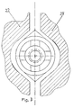
- two welding tongs 22, 24, shown schematically in FIG. 3 are used, which are complementary to the outline of the outer tube 14, their parting plane coinciding with the plane of symmetry of the two projections 20.
- the two welding tongs 22, 24 are provided with a suitable heating device in order to heat the plastic material of the inner bag (not shown) to the melting temperature. Because of the small cross-sectional area, the two projections 20 of the outer tube 14 are also melted in the region of the apex, so that a gas-tight connection of the inner bag to the riser tube holder 10 is ensured.
- the riser pipe holder 10 is fixed in the lid of an aerosol can, so that the riser pipe and the inner bag surrounding it are located within the can while the bead 18 protrudes upwards.
Landscapes
- Engineering & Computer Science (AREA)
- Mechanical Engineering (AREA)
- Chemical & Material Sciences (AREA)
- Dispersion Chemistry (AREA)
- Containers And Packaging Bodies Having A Special Means To Remove Contents (AREA)
Abstract
Die Erfindung betrifft einen Steigrohrhalter für ein mit einem Innenbeutel versehenes Ventil in einer Aerosoldose. Der Steigrohrhalter besteht aus einem einstückig gegossenen oder gespritzten Körper aus Kunststoff, umfassend zwei koaxial angeordnete Rohre, wobei ein Steigrohr über das innere Rohr und ein Ventil in einen nach oben über das innere Rohr vorstehenden Bereich des äußeren Rohres einsetzbar ist, und wobei der aus einer Kunststoffolie oder einem Folienlaminat bestehende Innenbeutel mit einem unteren Bereich des äußeren Rohres verschweißbar ist. Das äußere Rohr (14) ist im unteren Bereich an seiner Außenseite mit zwei axial verlaufenden flügelartigen Vorsprüngen (20) versehen, die einen sich radial nach außen verjüngenden Querschnitt haben.
Description
- Die Erfindung betrifft einen Steigrohrhalter für ein mit einem Innenbeutel versehenes Ventil in einer Aerosoldose, bestehend aus einem einstückig gegossenen oder gespritzten Körper aus Kunststoff, umfassend zwei koaxial angeordnete Rohre, wobei ein Steigrohr über das innere Rohr und ein Ventil in einen nach oben über das innere Rohr vorstehenden Bereich des äußeren Rohres einsetzbar ist, und wobei der aus einer Kunststoffolie oder einem Folienlaminat bestehende Innenbeutel mit einem unteren Bereich des äußeren Rohres verschweißbar ist.
- Bei einem bekannten Steigrohrhalter dieser Gattung hat das äußere Rohr einen zylindrischen Querschnitt. Zum Verschweißen des Innenbeutels mit dem äußeren Rohr des Steigrohrhalters dient eine zweiteilige Schweißzange, deren beide Backen spiegelbildlich ausgebildet sind und sich im geschlossenen Zustand eng an den Außenumfang des äußeren Rohres anschmiegen. In der Praxis haben sich beim Verschweißen des Innenbeutels mit dem Steigrohrhalter jedoch Schwierigkeiten ergeben. Es besteht die Gefahr, daß die Verschweißung in demjenigen Bereich, wo die beiden Schweißbacken aneinanderstoßen, ungenügend ist, so daß Kapillaren auftreten. Durch diese Kapillaren kann aber der Inhalt des Innenbeutels unter dem Druck des in der Aerosoldose befindlichen Treibgases entweichen und sich mit dem Treibgas vermengen.
- Der Erfindung liegt die Aufgabe zugrunde, den gattungsgemäßen Steigrohrhalter dahingehend zu verbessern, daß eine gasdichte Verschweißung mit dem Innenbeutel gewährleistet ist.
- Erfindungsgemäß wird diese Aufgabe dadurch gelöst, daß das äußere Rohr im unteren Bereich an seiner Außenseite mit zwei axial verlaufenden flügelartigen Vorsprüngen versehen ist, die einen sich radial nach außen verjüngenden Querschnitt haben.
- Diese flügelartigen Vorsprünge haben zur Folge, daß die beiden Schweißbacken am Übergang in die Trennebene stumpfe Winkel aufweisen und sich daher besser an den Steigrohrhalter anschmiegen können als dies bei einem zylindrischen Umfang der Fall ist. Da die beiden flügelartigen Vorsprünge einen sich radial nach außen verjüngenden Querschnitt haben, werden sie im Bereich des Scheitels bis auf die Schmelztemperatur erhitzt, so daß auch im Bereich der Trennebene der beiden Schweißbacken eine gasdichte Verbindung des Innenbeutels mit dem Steigrohrhalter gewährleistet ist.
- Vorzugsweise liegen die beiden flügelartigen Vorsprünge einander gegenüber, so daß die beiden Schweißbacken spiegelsymmetrisch ausgebildet sein können.
- Bei einer besonders vorteilhaften Ausführungsform des erfindungsgemäßen Steigrohrhalters ist vorgesehen, daß die Seitenflächen der beiden Vorsprünge tangential in das äußere Rohr übergehen.
- Ein Ausführungsbeispiel der Erfindung ist in den Zeichnungen dargestellt und wird nachfolgend näher erläutert. Es zeigt:
- Fig. 1 einen Längsschnitt durch den Steigrohrhalter nach der Linie A-A in Fig. 2,
- Fig. 2 eine Endansicht des Steigrohrhalters gemäß Fig. 1 von links gesehen, und
- Fig. 3 eine Darstellung ähnlich wie Fig. 2, in der zwei Schweißbacken schematisch dargestellt sind.
- Der in Fig. 1 gezeigte und allgemein mit dem Bezugszeichen 10 bezeichnete Steigrohrhalter dient zur Verwendung bei einer mit einem Innenbeutel versehenen Aerosoldose. Derartige Aerosoldosen werden für Produkte verwendet, die nicht mit dem Treibgas in Verbindung kommen dürfen, wie z.B. ein selbstschäumendes Gel.
- Der Steigrohrhalter 10 besteht aus einem einstückigen, gegossenen oder gespritzten Körper aus Kunststoff, insbesondere Polyethylen. Der Steigrohrhalter 10 umfaßt ein inneres Rohr 12 und ein zu diesem koaxial angeordnetes äußeres Rohr 14. Diese beiden Rohre 12 und 14 sind durch vier radiale Stege 16 miteinander verbunden. Wie aus Fig. 1 hervorgeht, sind die beiden Rohre 12 und 14 unterschiedlich lang, so daß das äußere Rohr 14 über das innere Rohr 12 vorsteht. Der vorstehende Bereich des äußeren Rohres 14 ist am freien Ende aus einem nachfolgend erläuterten Zweck mit einem nach außen vorspringenden Wulstrand 18 versehen. Vom gegenüberliegenden Ende des äußeren Rohres 14 erstrecken sich zwei einander diametral gegenüberliegende flügelartige Vorsprünge 20 bis über die Mitte hinaus. Wie aus Fig. 2 ersichtlich ist, gehen diese beiden flügelartigen Vorsprünge 20 tangential in den Umfang des äußeren Rohres 14 über. Die beiden Vorsprünge 20 haben daher einen sich radial nach außen verjüngenden dreieckigen Querschnitt.
- In das innere Rohr 12 kann ein Steigrohr eingesetzt werden, und in den über das innere Rohr 12 vorstehenden Bereich des äußeren Rohres 14 kann ein (nicht gezeigtes) Ventil eingesetzt werden, dessen Teller um den Wulstrand 18 des äußeren Rohres 14 umgebördelt wird. Ein (nicht gezeigter) Innenbeutel aus einer Kunststoffolie, vorzugsweise Polyethylen, oder aus einem Kunststoff-Aluminium-Kunststoff-Laminat wird mit dem äußeren Rohr 14 um Bereich der flügelartigen Vorsprünge 20 verschweißt. Hierzu dienen zwei in Fig. 3 schematisch dargestellte Schweißzangen 22, 24, die zum Umriß des äußeren Rohres 14 komplementär sind, wobei ihre Trennebene mit der Symmetrieebene der beiden Vorsprünge 20 zusammenfällt. Die beiden Schweißzangen 22, 24 sind mit einer geeigneten Heizeinrichtung versehen, um das Kunststoffmaterial des (nicht gezeigten) Innenbeutels auf Schmelztemperatur zu erhitzen. Wegen der geringen Querschnittsfläche werden dabei auch die beiden Vorsprünge 20 des äußeren Rohres 14 im Bereich des Scheitels geschmolzen, so daß eine gasdichte Verbindung des Innenbeutels mit dem Steigrohrhalter 10 gewährleistet ist.
- Auch wenn dies in der Zeichnung nicht dargestellt ist, so ist dem Fachmann bekannt, daß der Steigrohrhalter 10 im Deckel einer Aerosoldose festgelegt ist, so daß sich das Steigrohr und der dieses umgebende Innenbeutel innerhalb der Dose befinden, während der Wulstrand 18 nach oben vorspringt.
Claims (3)
- Steigrohrhalter für ein mit einem Innenbeutel versehenes Ventil in einer Aerosoldose, bestehend aus einem einstückig gegossenen oder gespritzten Körper aus Kunststoff, umfassend zwei koaxial angeordnete Rohre, wobei ein Steigrohr über das innere Rohr und ein Ventil in einen nach oben über das innere Rohr vorstehenden Bereich des äußeren Rohres einsetzbar ist, und wobei der aus einer Kunststoffolie oder einem Folienlaminat bestehende Innenbeutel mit einem unteren Bereich des äußeren Rohres verschweißbar ist, dadurch gekennzeichnet, daß das äußere Rohr (14) im unteren Bereich an seiner Außenseite mit zwei axial verlaufenden flügelartigen Vorsprüngen (20) versehen ist, die einen sich radial nach außen verjüngenden Querschnitt haben.
- Steigrohrhalter nach Anspruch 1, dadurch gekennzeichnet, daß die Vorsprünge (20) einander diamtetral gegenüberliegen.
- Steigrohrhalter nach Anspruch 1 oder 2, dadurch gekennzeichnet, daß die Seitenflächen der beiden Vorsprünge (20) tangential in das äußere Rohr (14) übergehen.
Applications Claiming Priority (2)
| Application Number | Priority Date | Filing Date | Title |
|---|---|---|---|
| DE9300288U DE9300288U1 (de) | 1993-01-12 | 1993-01-12 | Steigrohrhalter an einem Ventil für Aerosoldosen |
| DE9300288U | 1993-01-12 |
Publications (2)
| Publication Number | Publication Date |
|---|---|
| EP0606526A2 true EP0606526A2 (de) | 1994-07-20 |
| EP0606526A3 EP0606526A3 (de) | 1995-04-26 |
Family
ID=6888024
Family Applications (1)
| Application Number | Title | Priority Date | Filing Date |
|---|---|---|---|
| EP93112641A Withdrawn EP0606526A3 (de) | 1993-01-12 | 1993-08-06 | Steigrohrhalter an einem Ventil für Aerosoldosen. |
Country Status (2)
| Country | Link |
|---|---|
| EP (1) | EP0606526A3 (de) |
| DE (1) | DE9300288U1 (de) |
Cited By (4)
| Publication number | Priority date | Publication date | Assignee | Title |
|---|---|---|---|---|
| EP0820854A1 (de) * | 1996-07-23 | 1998-01-28 | RAPID SPRAY GmbH & Co. KG, FABRIK CHEM. ERZEUGNISSE | Werkzeug zum gasdichten Verbinden des Innenbeutels einer Aerosoldose mit dem Ventilhalter |
| EP0988958A3 (de) * | 1998-09-22 | 2000-10-04 | Fresenius Medical Care Deutschland GmbH | Verfahren und Vorrichtung zum Verschweissen einer Folie |
| EP1985555A1 (de) * | 2007-04-23 | 2008-10-29 | Crown Packaging Technology, Inc | Aerosoldose |
| EP2263860A1 (de) * | 2009-06-17 | 2010-12-22 | 3L-Ludvigsen A/S | Ultraschallversiegelungsklemme und Verfahren zur Ultraschallversiegelung |
Families Citing this family (1)
| Publication number | Priority date | Publication date | Assignee | Title |
|---|---|---|---|---|
| FR2811643B1 (fr) * | 2000-07-13 | 2003-03-21 | Lindal France | Corps de valve pour pulverisateur |
Family Cites Families (6)
| Publication number | Priority date | Publication date | Assignee | Title |
|---|---|---|---|---|
| ES290341A1 (es) * | 1962-11-17 | 1963-12-01 | Solfrene Macchine Societr Per | Perfeccionamientos en valvulas para aerosoles |
| GB740635A (en) * | 1963-07-06 | 1955-11-16 | Metal Box Co Ltd | Improvements in or relating to dispensing flowable products by gaseous pressure |
| US3317090A (en) * | 1965-09-13 | 1967-05-02 | Meshberg Philip | Dispensing means and valve means therefor |
| US3992003A (en) * | 1975-10-24 | 1976-11-16 | Visceglia Marco P | Aerosol container having sealed propellant means |
| US4475667A (en) * | 1983-01-06 | 1984-10-09 | Seaquist Valve Company | Aerosol assembly for signalling depletion of a preselected amount of _the container contents when in an inverted position |
| DE4121857A1 (de) * | 1991-07-02 | 1993-01-07 | Ladoco Ag | Druckbehaelter fuer gase, fluessigkeiten, pastoese produkte oder dergleichen |
-
1993
- 1993-01-12 DE DE9300288U patent/DE9300288U1/de not_active Expired - Lifetime
- 1993-08-06 EP EP93112641A patent/EP0606526A3/de not_active Withdrawn
Cited By (6)
| Publication number | Priority date | Publication date | Assignee | Title |
|---|---|---|---|---|
| EP0820854A1 (de) * | 1996-07-23 | 1998-01-28 | RAPID SPRAY GmbH & Co. KG, FABRIK CHEM. ERZEUGNISSE | Werkzeug zum gasdichten Verbinden des Innenbeutels einer Aerosoldose mit dem Ventilhalter |
| EP0988958A3 (de) * | 1998-09-22 | 2000-10-04 | Fresenius Medical Care Deutschland GmbH | Verfahren und Vorrichtung zum Verschweissen einer Folie |
| EP1985555A1 (de) * | 2007-04-23 | 2008-10-29 | Crown Packaging Technology, Inc | Aerosoldose |
| EP2263860A1 (de) * | 2009-06-17 | 2010-12-22 | 3L-Ludvigsen A/S | Ultraschallversiegelungsklemme und Verfahren zur Ultraschallversiegelung |
| WO2010145667A1 (en) * | 2009-06-17 | 2010-12-23 | 3L Ludvigsen A/S | Ultrasonic sealing jaw and method for ultrasonic sealing |
| US8882946B2 (en) | 2009-06-17 | 2014-11-11 | 3L Ludvigsen A/S | Ultrasonic sealing jaw and method for ultrasonic sealing |
Also Published As
| Publication number | Publication date |
|---|---|
| DE9300288U1 (de) | 1993-03-04 |
| EP0606526A3 (de) | 1995-04-26 |
Similar Documents
| Publication | Publication Date | Title |
|---|---|---|
| DE2841900C2 (de) | Kleindimensioniertes Druckgefäß | |
| DE4120529C2 (de) | Quetschkupplung für flexible Schläuche | |
| DE69802584T2 (de) | Rohrkupplung | |
| DE3215171C2 (de) | Verfahren zum Herstellen eines tubenförmigen Behälters | |
| DE3322976C2 (de) | Verfahren zum Herstellen eines mit einem Verstärkungsring versehenen Papierbehälters | |
| DE2657398C3 (de) | Rohrverbindung für zwei Rohrstücke | |
| DE2630354C2 (de) | Metallischer Reaktordruckbehälter | |
| DE69311243T2 (de) | Demontierbare Vorrichtung zum Abgeben von Substanzen | |
| DE29780382U1 (de) | Behälter mit Druckausgleichsöffnungen | |
| DE2649721B2 (de) | Behälter und Verfahren und Vorrichtung zu dessen Herstellung | |
| EP0151751B1 (de) | Zylindrischer Behälter | |
| DE69901521T2 (de) | Heizgerät zum Heissiegeln von Behälterbodenteilen | |
| DE2333988C3 (de) | Verfahren zum Wiederinstandsetzen eines Behälters | |
| EP0677457A1 (de) | Quetschbarer Behälter für Speiseeis | |
| DE8207739U1 (de) | Auf einen eine zentrale Austrittsoeffnung aufweisenden Behaelter fuer Fluessigkeiten aufsetzbare Kappe | |
| DE9300288U1 (de) | Steigrohrhalter an einem Ventil für Aerosoldosen | |
| EP0820854B1 (de) | Verfahren zum gasdichten Verbinden des Innenbeutels einer Aerosoldose mit dem Ventilhalter | |
| CH618133A5 (en) | Dispensing container for viscous substances, in particular pastes | |
| EP0447997A2 (de) | Dosenartige Verpackung für fliessfähige Produkte und Verfahren zu ihrer Herstellung | |
| EP3137396B1 (de) | Verschlussanordnung, verfahren zum verschliessen eines verschlusses und schüttgutbehälter damit | |
| DE4432718A1 (de) | Packung mit flacher Öffnungsvorrichtung und Werkzeug zur Herstellung derselben | |
| DE60032734T2 (de) | Vorrichtung zum anschliessen einer zweigleitung an eine fluidführende leitung | |
| DE2363727A1 (de) | Schweissbare rohrfittings aus kunststoff | |
| DE4427270A1 (de) | Leiste zum abdichtenden Ausfüllen einer Fuge in einem Bauteil, insbesondere einer Kraftfahrzeugkarosserie | |
| DE102020129089A1 (de) | Energiespeicherzelle, Energiespeicher sowie Verfahren zum Herstellen einer Energiespeicherzelle |
Legal Events
| Date | Code | Title | Description |
|---|---|---|---|
| PUAI | Public reference made under article 153(3) epc to a published international application that has entered the european phase |
Free format text: ORIGINAL CODE: 0009012 |
|
| AK | Designated contracting states |
Kind code of ref document: A2 Designated state(s): AT CH DE FR GB IT LI |
|
| GBC | Gb: translation of claims filed (gb section 78(7)/1977) | ||
| EL | Fr: translation of claims filed | ||
| ITCL | It: translation for ep claims filed |
Representative=s name: BARZANO' E ZANARDO ROMA S.P.A. |
|
| PUAL | Search report despatched |
Free format text: ORIGINAL CODE: 0009013 |
|
| AK | Designated contracting states |
Kind code of ref document: A3 Designated state(s): AT CH DE FR GB IT LI |
|
| 18D | Application deemed to be withdrawn |
Effective date: 19951027 |