EP0606561A1 - Schreibgerät - Google Patents
Schreibgerät Download PDFInfo
- Publication number
- EP0606561A1 EP0606561A1 EP93118854A EP93118854A EP0606561A1 EP 0606561 A1 EP0606561 A1 EP 0606561A1 EP 93118854 A EP93118854 A EP 93118854A EP 93118854 A EP93118854 A EP 93118854A EP 0606561 A1 EP0606561 A1 EP 0606561A1
- Authority
- EP
- European Patent Office
- Prior art keywords
- front part
- holder shaft
- locking means
- writing
- external thread
- Prior art date
- Legal status (The legal status is an assumption and is not a legal conclusion. Google has not performed a legal analysis and makes no representation as to the accuracy of the status listed.)
- Granted
Links
- 230000000717 retained effect Effects 0.000 abstract 1
- 230000015572 biosynthetic process Effects 0.000 description 1
- 230000001419 dependent effect Effects 0.000 description 1
- 239000000203 mixture Substances 0.000 description 1
Images
Classifications
-
- B—PERFORMING OPERATIONS; TRANSPORTING
- B43—WRITING OR DRAWING IMPLEMENTS; BUREAU ACCESSORIES
- B43K—IMPLEMENTS FOR WRITING OR DRAWING
- B43K5/00—Pens with ink reservoirs in holders, e.g. fountain-pens
- B43K5/005—Pen barrels
Definitions
- the invention relates to a writing instrument according to the preamble of patent claim 1.
- Different writing instruments such as fountain pens, ballpoint pens, etc.
- a holder shaft and a front part screwed to it with a writing tip.
- the front part and holder shaft can be screwed apart so that ink or ink can be refilled or ink cartridges or a writing refill can be replaced.
- the holder shaft is provided with an internal thread at its open end and the front part with an external thread at its end facing away from the writing tip.
- the outer surface is provided with a pattern, for example in the form of colored or relief-like designs, which extend over the outer surfaces of the holder shaft and front part. Examples of this are grooves or colored lines that run longitudinally over the surface of the writing instrument.
- writing implements that are not exactly circular in cross-section to the longitudinal axis, but have, for example, an oval or polygonal cross-section.
- first locking means are provided in the holder shaft, which engage in the second locking means on the front part when the screw connection reaches the closed position and releasably lock the front part in the predetermined rotational position on the holder shaft and thus secure against further rotation.
- the first and second locking means are arranged in such a way that the front part and holder shaft engage when screwed together in the specified rotational position, which can ensure that the front part and holder shaft are in no way rotated relative to one another, but instead assume the specified closed position, so that coordinated surface configurations of both parts fit lie to each other and merge continuously.
- the first locking means are formed by at least one projection provided on the inner surface or the internal thread of the holder shaft and the second locking means by at least one recess provided on the outer surface or the external thread of the front part.
- each projection slides into an associated recess when the predetermined closed position is reached, and thus prevents the two parts from rotating further.
- the first locking means can of course also be formed by recesses and the second locking means by projections.
- the cooperating recesses or projections can be arranged outside the thread areas of the front part or the holder shaft or on the thread flanks in each case.
- the projections can engage in axial or radial recesses with respect to the longitudinal axis of the writing instrument.
- each projection is designed as a rib running on the inner surface in the longitudinal direction of the holder shaft, which begins from the open end of the holder shaft behind the internal thread and extends into the interior.
- the recesses have the shape of axial incisions.
- At least two ribs are provided on the inner surface of the holder shaft and at least two incisions in the outer edge of the cylindrical outer surface of the front part.
- the front edge of the outer surface of the front part is axially increasing from one incision to the next in the direction of the external thread in such a way that each incision has a high lateral boundary and a low lateral boundary, which is characterized by a lower than the high lateral Limit shaped axial Increase is formed. It is thereby achieved that each projection slides into the incision with relatively little resistance when the closing position is reached, and then strikes against the high lateral limitation, which prevents the front part from being screwed in further beyond the closing position. On the other hand, the projection is held in the incision by the axial elevation, so that a certain resistance has to be overcome to unscrew the front part from the holder shaft so that the projection slides out of the incision via the axial elevation and so the locking is released.
- the design of the holder shaft with at least two ribs running in its interior on the inner surface has the further advantage that inserts, such as ink containers, ink cartridges, etc., are kept centered in the interior of the holder shaft by the ribs.
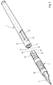
- FIG. 1 shows a writing instrument in the form of a fountain pen with a holder shaft 1 and a front part 2 with a writing tip 3.
- the holder shaft 1 is hollow and has an internal thread 11 at its open end on the inner surface 12.
- the front part 2 carries at its from the writing tip 3 opposite end an external thread 21 which is arranged on a cylindrical outer surface 22.
- the first locking means 13, 14 are formed by two ribs running in the axial direction, which begin on the inner surface 12 behind the internal thread 11 and continue on the inner surface 12 into the interior of the holder shaft 1.
- the second locking means 23, 24 are designed as incisions in the front edge 25, 26 of the cylindrical outer surface 22 of the front part 2.
- the first locking means 13, 14 and the second locking means are arranged with respect to one another such that each rib slides into an associated incision and engages there when the front part 2 reaches its predetermined closed position on the holder shaft 1 when screwed together.
- the locking ensures that the holder shaft 1 and the front part 2 have a predetermined rotational position in relation to one another in their closed position, so that patterns or surface designs on the surfaces 10 and 20 of the two parts 1, 2 are aligned with one another.
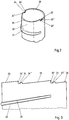
- FIG. 2 shows the end of the front part 2 facing away from the writing tip, which has a cylindrical outer surface 22 with an external thread 21.
- the second locking means 23, 24 have the form of axial incisions in the front edge 25, 26 of the cylindrical outer surface 22.
- the front edge 25, 26 is shaped in such a way that, starting from an incision 23 in the thread direction of the screw connection, it initially has an axial elevation, which forms a flat lateral boundary 23 ', and then rises in the region 26 of the edge to the next incision 24, so that an increased lateral boundary 24' is formed there.
- the edge region 25 between the two incisions 23, 24 also rises accordingly. This formation of the incisions and the front edge can be seen in Figure 3, in which the front Part of the cylindrical outer surface 22 is cut open at the lateral boundary 23 'and shown rolled.
- the ribs 13, 14 in the holder shaft 1 approach the incisions 23, 24 in the front edge 25, 26 of the front part 2 when approaching the closed position and finally slide over the axial elevations into the incisions 23, 24.
- the raised lateral boundaries 23 ', 24' then each form a stop, so that a further screwing of the front part 2 on the holder shaft 1 is prevented.
- the flatter shaped side boundaries 23 '', 24 '' offer the ribs 13, 14 a relatively lower resistance when sliding out of the incisions 23, 24, which is sufficient on the one hand to hold the two parts in their closed position and on the other hand by the Users can be overcome relatively easily when unscrewing.
Landscapes
- Engineering & Computer Science (AREA)
- Mechanical Engineering (AREA)
- Mechanical Pencils And Projecting And Retracting Systems Therefor, And Multi-System Writing Instruments (AREA)
- Pens And Brushes (AREA)
Abstract
Description
- Die Erfindung betrifft ein Schreibgerät nach dem Oberbegriff des Patentanspruchs 1.
- Es sind unterschiedliche Schreibgeräte, wie beispielsweise Füllfederhalter, Kugelschreiber etc. bekannt, die einen Halterschaft und ein damit verschraubtes Vorderteil mit einer Schreibspitze aufweisen. Vorderteil und Halterschaft sind auseinanderschraubbar ausgebildet, um Tinte oder Tusche auffüllen oder Tintenpatronen oder eine Schreibmine ersetzen zu können. Der Halterschaft ist aus diesem Grund an seinem offenen Ende mit einem Innengewinde und das Vorderteil an seinem von der Schreibspitze abgewandten Ende mit einem Außengewinde versehen.
- Bei einigen Schreibgeräten ist die Außenfläche mit einer Musterung, etwa in Form von farblichen oder reliefartigen Gestaltungen versehen, die sich über die Außenflächen von Halterschaft und Vorderteil ziehen. Beispiele dafür sind Rillen oder farbige Striche, die in Längsrichtung über die Oberfläche des Schreibgerätes verlaufen. Ebenso gibt es Schreibgeräte, die im Querschnitt zur Längsachse nicht exakt kreisförmig sind, sondern beispielweise einen ovalen oder polygonalen Querschnitt haben. Bei den genannten Gestaltungen ergibt sich der Nachteil, daß nach dem Zusammenschrauben von Halterschaft und Vorderteil diese in ihrer Schließstellung in der Regel nicht passend zueinander ausgerichtet sind. Die Oberflächengestaltungen von Halterschaft und Vorderteil gehen daher in der Regel nicht passend ineinander über, sondern sind gegeneinander verdreht, wenn sie vom Benutzer nicht genau zueinander eingestellt werden. Die exakte Einstellung beider Teile zueinander ist für den Benutzer zum einen mühsam, und zum anderen ist dabei nicht sichergestellt, daß in der nach der Oberflächgestaltung richtigen Einstellung beider Teile eine feste und sichere Verschlußstellung der Schraubverbindung gewährleistet wird.
- Es ist Aufgabe der Erfindung, ein aus zwei miteinander zu verschraubenden Teilen bestehendes Schreibgerät zu schaffen, bei dem beide Teile nach dem Zusammenschrauben eine Schließposition mit vorgegebener Drehstellung zueinander einnehmen.
- Zur Lösung dieser Aufgabe dienen die kennzeichnenden Merkmale des Patentanspruchs 1 in Verbindung mit dessen Oberbegriff. Vorteilhafte Ausgestaltungen sind Gegenstand der Unteransprüche.
- Erfindungsgemäß sind in dem Halterschaft erste Arretiermittel vorgesehen, die bei Erreichen der Schließposition der Schraubverbindung in zweite Arretiermittel am Vorderteil eingreifen und das Vorderteil in der vorgegebenen Drehstellung am Halterschaft lösbar arretieren und so gegen gegen weiteres Verdrehen sichern. Die ersten und zweiten Arretiermittel sind so zueinander angeordnet, daß Vorderteil und Halterschaft beim Zusammenschrauben in der vorgegebenen Drehstellung einrasten, wodurch gewährleistet werden kann, daß Vorderteil und Halterschaft keinesfalls verdreht zueinander stehen, sondern die vorgegebene Schließposition einnehmen, so daß aufeinander abgestimmte Oberflächengestaltungen beider Teile passend zueinander liegen und stetig ineinander übergehen.
- In einer vorteilhaften Ausgestaltung werden die ersten Arretiermittel durch wenigstens einen an der Innenfläche oder dem Innengewinde des Halterschaftes vorgesehenen Vorsprung und die zweiten Arretiermittel durch wenigstens eine an der Außenfläche oder dem Außengewinde des Vorderteils vorgesehene Ausnehmung gebildet. Beim Zusammenschrauben beider Schreibgerätteile gleitet jeder Vorsprung bei Erreichen der vorgegebenen Schließposition in eine zugeordnete Ausnehmung und verhindert so ein weiteres Verdrehen beider Teile gegeneinander. Grundsätzlich können natürlich auch umgekehrt die ersten Arretiermittel durch Ausnehmungen und die zweiten Arretiermittel durch Vorsprünge gebildet werden. Die zusammenwirkenden Ausnehmungen bzw. Vorsprünge können außerhalb der Gewindebereiche des Vorderteils bzw. des Halterschafts oder jeweils an den Gewindeflanken angeordnet sein. Die Vorsprünge können in bezüglich der Längsachse des Schreibgerätes axiale oder radiale Ausnehmungen eingreifen.
- In einer weiteren vorteilhaften Ausgestaltung ist jeder Vorsprung als eine an der Innenfläche in Längsrichtung des Halterschaftes verlaufende Rippe ausgebildet, die von dem offenen Ende des Halterschaftes aus hinter dem Innengewinde beginnt und in das Innere verläuft. Entsprechend dazu haben im vorderen Rand der das Außengewinde tragenden zylindrischen Außenfläche des Vorderteils die Ausnehmungen die Form von axialen Einschnitten.
- In einer vorteilhaften Ausgestaltung sind wenigstens zwei Rippen an der Innenfläche des Halterschaftes und wenigstens zwei Einschnitte im äußeren Rand der zylindrischen Außenfläche des Vorderteils vorgesehen.
- In einer weiteren vorteilhaften Ausgestaltung ist der vordere Rand der Außenfläche des Vorderteils von einem Einschnitt zum nächsten in Gangrichtung des Außengewindes axial in der Weise ansteigend ausgebildet, daß jeder Einschnitt eine hohe seitliche Begrenzung und eine niedrige seitliche Begrenzung, welche durch eine niedriger als die hohe seitliche Begrenzung geformte axiale Erhöhung gebildet wird, aufweist. Dadurch wird erreicht, daß jeder Vorsprung bei Erreichen der Schließposition mit relativ geringem Widerstand über die flach ausgebildete axiale Erhöhung in den Einschnitt gleitet und dann gegen die hohe seitliche Begrenzung anschlägt, was ein weiteres Einschrauben des Vorderteils über die Schließposition hinaus verhindert. Auf der anderen Seite wird der Vorsprung durch die axiale Erhöhung in dem Einschnitt festgehalten, so daß zum Abschrauben des Vorderteils vom Halterschaft ein gewisser Widerstand überwunden werden muß, damit der Vorsprung über die axiale Erhöhung aus dem Einschnitt herausgleitet und so die Arretierung gelöst wird.
- Die Ausgestaltung des Halterschafts mit wenigstens zwei in seinem Inneraum an der Innenfläche verlaufenden Rippen hat den weiteren Vorteil, daß Einsätze, wie etwa Tintenbehälter, Tintenpatronen, etc., im Innenraum des Halterschaftes durch die Rippen zentriert gehalten werden.
- Die Erfindung wird im folgenden an Hand eines Ausführungsbeispiels in den Zeichnungen erläutert, in denen:
- Figur 1
- eine perspektivische, teilweise aufgebrochene Darstellung eines auseinandergeschraubten Schreibgerätes ist;
- Figur 2
- eine perspektivische Darstellung des von der Schreibspitze abgewandten Endes des Vorderteils ist; und
- Figur 3
- eine abgerollte Darstellung des vorderen zylindrischen Endes des Vorderteils aus Figur 2 ist.
- In Figur 1 ist ein Schreibgerät in Form eines Füllfederhalters mit einem Halterschaft 1 und einem Vorderteil 2 mit Schreibspitze 3 gezeigt. Der Halterschaft 1 ist hohl und weist an seinem offenen Ende an der Innenfläche 12 ein Innengewinde 11 auf. Demgegenüber trägt das Vorderteil 2 an seinem von der Schreibspitze 3 abgewandten Ende ein Außengewinde 21, das auf einer zylindrischen Außenfläche 22 angeordnet ist.
- Die ersten Arretiermittel 13, 14 werden in dem Ausführungsbeispiel durch zwei in axialer Richtung verlaufende Rippen gebildet, die an der Innenfläche 12 hinter dem Innengewinde 11 beginnen und an der Innenfläche 12 weiter in das Innere des Halterschaftes 1 verlaufen. Dementsprechend sind die zweiten Arretiermittel 23, 24 als Einschnitte im vorderen Rand 25, 26 der zylindrischen Außenfläche 22 des Vorderteils 2 gestaltet. Die ersten Arretiermittel 13, 14 und die zweiten Arretiermittel sind derart zueinander angeordnet, daß jede Rippe jeweils in einen zugehörigen Einschnitt gleitet und dort einrastet, wenn das Vorderteil 2 beim Zusammenschrauben seine vorgegeben Schließposition am Halterschaft 1 erreicht. Durch die Arretierung wird erreicht, daß Halterschaft 1 und Vorderteil 2 in ihrer Schließposition eine vorgegebene Drehstellung zueinander haben, so daß Muster oder Oberflächengestaltungen an den Oberflächen 10 und 20 der beiden Teile 1,2 passend zueinander ausgerichtet sind.
- Die Ausbildung der zweiten Arretiermittel 23, 24 ist in den Figuren 2 und 3 genauer dargestellt. Figur 2 zeigt das von der Schreibspitze abgewandte Ende des Vorderteils 2, das eine zylindrische Außenfläche 22 mit einem Außengewinde 21 aufweist. Die zweiten Arretiermittel 23, 24 haben die Form von axialen Einschnitten im vorderen Rand 25, 26 der zylindrischen Außenfläche 22. Der vordere Rand 25, 26 ist so geformt, daß er ausgehend von einem Einschnitt 23 in Gangrichtung der Schraubverbindung zunächst eine axiale Erhöhung aufweist, die eine flache seitliche Begrenzung 23' bildet, und anschließend in dem Bereich 26 des Randes zum nächsten Einschnitt 24 hin ansteigt, so daß dort eine erhöhte seitliche Begrenzung 24' gebildet wird. Entsprechend steigt auch der Randbereich 25 zwischen den beiden Einschnitten 23, 24 an. Diese Ausbildung der Einschnitte und des vorderen Randes ist in Figur 3 zu erkennen, in der der vordere Teil der zylindrischen Außenfläche 22 an der seitlichen Begrenzung 23' aufgeschnitten und abgerollt dargestellt ist.
- Beim Zusammenschrauben von Vorderteil 2 und Halterschaft 1 nähern sich die Rippen 13, 14 im Halterschaft 1 bei Annäherung an die Schließposition den Einschnitten 23, 24 im vorderen Rand 25, 26 des Vorderteils 2 an und gleiten schließlich über die axialen Erhöhungen in die Einschnitte 23, 24. Die erhöhten seitlichen Begrenzungen 23', 24' bilden dann jeweils einen Anschlag, so daß ein weiteres Verschrauben des Vorderteils 2 am Halterschaft 1 verhindert wird. Die flacher geformten seitlichen Begrenzungen 23'', 24'' bieten den Rippen 13, 14 beim Herausgleiten aus den Einschnitten 23, 24 einen relativ geringeren Widerstand, der einerseits ausreichend ist, um die beiden Teile in ihrer Schließposition festzuhalten, und der andererseits von dem Benutzer beim Losschrauben relativ leicht überwunden werden kann.
Claims (5)
- Schreibgerät, mit einem Halterschaft (1) und einem eine Schreibspitze (3) aufweisenden Vorderteil (2), wobei der Halterschaft (1) an einem Ende offen und mit einem Innengewinde (11) versehen ist, in das das Vorderteil (2) mit einem an dem der Schreibspitze (3) abgewandten Ende liegenden Außengewinde (21) einschraubbar ist, dadurch gekennzeichnet, daß an der Innenfläche (12) oder dem Innengewinde (11) des Halterschaftes (1) erste Arretiermittel (13, 14) und an der Außenfläche (22) oder dem Außengewinde (21) des Vorderteils (2) zweite Arretiermittel (23, 24) vorgesehen sind, die so zueinander angeordnet sind, daß die ersten Arretiermittel (13, 14) und die zweiten Arretiermittel (23, 24) in einer vorgegebenen Verschraubungsposition ineinandergreifen und das Vorderteil (2) gegen weiteres Verschrauben am Halterschaft (1) arretiert wird.
- Schreibgerät nach Anspruch 1, dadurch gekennzeichnet, daß die einen Arretiermittel (13, 14) durch wenigstens einen an der Innenfläche (12) oder dem Innengewinde (11) des Halterschaftes (1) vorgesehenen Vorsprung und die anderen Arretiermittel (23, 24) durch wenigstens eine an der Außenfläche (22) oder dem Außengewinde (21) des Vorderteils (2) vorgesehene Ausnehmung gebildet werden, die in der vorgegebenen Verschraubungsposition ineinandergreifen und Vorderteil (2) und Halterschaft (1) gegen weiteres Verschrauben lösbar arretieren.
- Schreibgerät nach Anspruch 2, dadurch gekennzeichnet, daß jeder Vorsprung durch eine an der Innenfläche (12) in Längsrichtung des Halterschaftes (1) verlaufende Rippe (23, 24) gebildet wird, die vom offenen Ende aus hinter dem Innengewinde (11) beginnt und in das Innere des Halterschaftes (1) verläuft, und daß jede Ausnehmung durch einen axialen Einschnitt (23, 24) im äußeren Rand der das Außengewinde (21) tragenden zylindrischen Außenfläche (22) des Vorderteils (2) gebildet wird.
- Schreibgerät nach Anspruch 3, dadurch gekennzeichnet, daß wenigstens zwei Rippen (13, 14) an der Innenfläche (12) des Halterschaftes (1) und wenigstens zwei axiale Einschnitte (23, 24) im äußeren Rand (25, 26) der zylindrischen Wandfläche (22) des Vorderteils (2) vorgesehen sind.
- Schreibgerät nach Anspruch 4, dadurch gekennzeichnet, daß der äußere Rand (25, 26) der Außenfläche des Vorderteils (2) von einem Einschnitt zum nächsten in Gangrichtung des Außengewindes (21) in der Weise ansteigt, daß jeder Einschnitt (23, 24) eine hohe seitliche Begrenzung (23', 24') und eine niedrige seitliche Begrenzung (23'', 24''), die durch eine niedriger als die hohe seitliche Begrenzung geformte axiale Erhöhung gebildet wird, aufweist.
Applications Claiming Priority (2)
| Application Number | Priority Date | Filing Date | Title |
|---|---|---|---|
| DE4301161A DE4301161C2 (de) | 1993-01-12 | 1993-01-12 | Schreibgerät |
| DE4301161 | 1993-01-12 |
Publications (2)
| Publication Number | Publication Date |
|---|---|
| EP0606561A1 true EP0606561A1 (de) | 1994-07-20 |
| EP0606561B1 EP0606561B1 (de) | 1997-03-12 |
Family
ID=6478402
Family Applications (1)
| Application Number | Title | Priority Date | Filing Date |
|---|---|---|---|
| EP93118854A Expired - Lifetime EP0606561B1 (de) | 1993-01-12 | 1993-11-24 | Schreibgerät |
Country Status (2)
| Country | Link |
|---|---|
| EP (1) | EP0606561B1 (de) |
| DE (2) | DE4301161C2 (de) |
Cited By (1)
| Publication number | Priority date | Publication date | Assignee | Title |
|---|---|---|---|---|
| WO2002006060A1 (de) * | 2000-07-18 | 2002-01-24 | Schwan-Stabilo Schwanhäusser Gmbh & Co. | Stift, schreibeinheit und vorrichtung zum halten einer schreibeinheit |
Families Citing this family (1)
| Publication number | Priority date | Publication date | Assignee | Title |
|---|---|---|---|---|
| FR2899842B1 (fr) * | 2006-04-13 | 2008-07-04 | Bic Soc | Instrument d'ecriture comprenant une tete assemblee avec un corps et bloquee en rotation |
Citations (5)
| Publication number | Priority date | Publication date | Assignee | Title |
|---|---|---|---|---|
| FR2036272A5 (de) * | 1969-03-12 | 1970-12-24 | Boussois Souchon Neuvesel Sa | |
| GB2105693A (en) * | 1981-07-31 | 1983-03-30 | Ug Closures And Plastics Limit | Closures and containers |
| DE3206998A1 (de) * | 1982-02-26 | 1983-09-15 | Pelikan Ag, 3000 Hannover | Durch drehbewegung loesbare verbindung |
| JPS6048471U (ja) * | 1983-09-13 | 1985-04-05 | 株式会社パイロット | 筆記具における軸筒の連結構造 |
| GB2260945A (en) * | 1991-10-30 | 1993-05-05 | Sakura Color Prod Corp | Non-releasable screw-threaded assembly of a writing instrument |
-
1993
- 1993-01-12 DE DE4301161A patent/DE4301161C2/de not_active Expired - Lifetime
- 1993-11-24 EP EP93118854A patent/EP0606561B1/de not_active Expired - Lifetime
- 1993-11-24 DE DE59305762T patent/DE59305762D1/de not_active Expired - Fee Related
Patent Citations (5)
| Publication number | Priority date | Publication date | Assignee | Title |
|---|---|---|---|---|
| FR2036272A5 (de) * | 1969-03-12 | 1970-12-24 | Boussois Souchon Neuvesel Sa | |
| GB2105693A (en) * | 1981-07-31 | 1983-03-30 | Ug Closures And Plastics Limit | Closures and containers |
| DE3206998A1 (de) * | 1982-02-26 | 1983-09-15 | Pelikan Ag, 3000 Hannover | Durch drehbewegung loesbare verbindung |
| JPS6048471U (ja) * | 1983-09-13 | 1985-04-05 | 株式会社パイロット | 筆記具における軸筒の連結構造 |
| GB2260945A (en) * | 1991-10-30 | 1993-05-05 | Sakura Color Prod Corp | Non-releasable screw-threaded assembly of a writing instrument |
Cited By (2)
| Publication number | Priority date | Publication date | Assignee | Title |
|---|---|---|---|---|
| WO2002006060A1 (de) * | 2000-07-18 | 2002-01-24 | Schwan-Stabilo Schwanhäusser Gmbh & Co. | Stift, schreibeinheit und vorrichtung zum halten einer schreibeinheit |
| US6905273B2 (en) | 2000-07-18 | 2005-06-14 | Gerhard Huttner | Pen, writing unit and a device for holding a writing unit |
Also Published As
| Publication number | Publication date |
|---|---|
| DE59305762D1 (de) | 1997-04-17 |
| DE4301161C2 (de) | 1997-01-16 |
| DE4301161A1 (de) | 1994-07-14 |
| EP0606561B1 (de) | 1997-03-12 |
Similar Documents
| Publication | Publication Date | Title |
|---|---|---|
| DE69920530T2 (de) | Schlüssel für ein Zylinderschloss | |
| DE69819969T2 (de) | Bohrer mit Spannuten mit abwechselnd wendelförmigen und geraden Abschnitten | |
| DE29504857U1 (de) | Bohrlehre für chirurgische Bohrwerkzeuge | |
| EP1268301A1 (de) | Schraubkappe mit pinsel | |
| EP0436496A1 (de) | Schlüssel für Schliesszylinder, insbesondere von Schliessanlagen | |
| DE19549053C2 (de) | Sicherheitsschloß mit einem Schließzylinder und einem Schlüssel mit flachem Schaft | |
| DE3142520A1 (de) | Zeichenstift | |
| DE2903355C2 (de) | Kombi-Schreibgerät | |
| DE2716359A1 (de) | Druckschreibgeraet | |
| DE3119626C2 (de) | Aus Flachzylinder und zugehörigen Flachschlüsseln bestehende Schließanlage | |
| DE19813153C2 (de) | Füllfederhalter | |
| DE3836872C2 (de) | Aus Flachschlüssel und Schließzylinder bestehende Schließvorrichtung | |
| EP1478483A1 (de) | Werkzeugverbindung | |
| EP0606561B1 (de) | Schreibgerät | |
| DE2732518A1 (de) | Schreibgeraet | |
| DE2159522B2 (de) | Röhrchenschreiber | |
| DE19602852C1 (de) | Schreibgerät mit Drehmechanik und mit versenkbarer Schreibspitze | |
| DE3206998C2 (de) | ||
| DE19725401C1 (de) | Bohrvorrichtung mit Begrenzung des Bohrweges | |
| DE19602851A1 (de) | Schreibgerät mit versenkbarer Schreibspitze und mit Klipp | |
| DE2532626C3 (de) | Vorrichtung zum Auswechseln von Minen eines Schreibgerätes | |
| DE29601199U1 (de) | Schreibgerät mit Drehmechanik und mit versenkbarer Schreibspitze | |
| DE3210681A1 (de) | Schreibinstrument | |
| DE2759745C2 (de) | Möbelscharnier, insbesondere für Stilmöbel | |
| EP1425189B1 (de) | Kappe für ein schreib-, zeichen- oder malgerät |
Legal Events
| Date | Code | Title | Description |
|---|---|---|---|
| PUAI | Public reference made under article 153(3) epc to a published international application that has entered the european phase |
Free format text: ORIGINAL CODE: 0009012 |
|
| 17P | Request for examination filed |
Effective date: 19931124 |
|
| AK | Designated contracting states |
Kind code of ref document: A1 Designated state(s): DE FR GB IT |
|
| 17Q | First examination report despatched |
Effective date: 19951016 |
|
| GRAG | Despatch of communication of intention to grant |
Free format text: ORIGINAL CODE: EPIDOS AGRA |
|
| GRAG | Despatch of communication of intention to grant |
Free format text: ORIGINAL CODE: EPIDOS AGRA |
|
| GRAH | Despatch of communication of intention to grant a patent |
Free format text: ORIGINAL CODE: EPIDOS IGRA |
|
| GRAH | Despatch of communication of intention to grant a patent |
Free format text: ORIGINAL CODE: EPIDOS IGRA |
|
| GRAA | (expected) grant |
Free format text: ORIGINAL CODE: 0009210 |
|
| AK | Designated contracting states |
Kind code of ref document: B1 Designated state(s): DE FR GB IT |
|
| ITF | It: translation for a ep patent filed | ||
| REF | Corresponds to: |
Ref document number: 59305762 Country of ref document: DE Date of ref document: 19970417 |
|
| ET | Fr: translation filed | ||
| GBT | Gb: translation of ep patent filed (gb section 77(6)(a)/1977) |
Effective date: 19970603 |
|
| PLBI | Opposition filed |
Free format text: ORIGINAL CODE: 0009260 |
|
| PLBQ | Unpublished change to opponent data |
Free format text: ORIGINAL CODE: EPIDOS OPPO |
|
| 26 | Opposition filed |
Opponent name: SCHNEIDER GMBH & CO. PRODUKTIONS- UND VERTRIEBS-KG Effective date: 19970708 |
|
| PLBF | Reply of patent proprietor to notice(s) of opposition |
Free format text: ORIGINAL CODE: EPIDOS OBSO |
|
| PLBF | Reply of patent proprietor to notice(s) of opposition |
Free format text: ORIGINAL CODE: EPIDOS OBSO |
|
| PLBO | Opposition rejected |
Free format text: ORIGINAL CODE: EPIDOS REJO |
|
| PLBN | Opposition rejected |
Free format text: ORIGINAL CODE: 0009273 |
|
| STAA | Information on the status of an ep patent application or granted ep patent |
Free format text: STATUS: OPPOSITION REJECTED |
|
| 27O | Opposition rejected |
Effective date: 19990427 |
|
| PGFP | Annual fee paid to national office [announced via postgrant information from national office to epo] |
Ref country code: DE Payment date: 19991122 Year of fee payment: 7 |
|
| PGFP | Annual fee paid to national office [announced via postgrant information from national office to epo] |
Ref country code: GB Payment date: 19991124 Year of fee payment: 7 |
|
| PGFP | Annual fee paid to national office [announced via postgrant information from national office to epo] |
Ref country code: FR Payment date: 19991129 Year of fee payment: 7 |
|
| PG25 | Lapsed in a contracting state [announced via postgrant information from national office to epo] |
Ref country code: GB Free format text: LAPSE BECAUSE OF NON-PAYMENT OF DUE FEES Effective date: 20001124 |
|
| GBPC | Gb: european patent ceased through non-payment of renewal fee |
Effective date: 20001124 |
|
| PG25 | Lapsed in a contracting state [announced via postgrant information from national office to epo] |
Ref country code: FR Free format text: LAPSE BECAUSE OF NON-PAYMENT OF DUE FEES Effective date: 20010731 |
|
| PG25 | Lapsed in a contracting state [announced via postgrant information from national office to epo] |
Ref country code: DE Free format text: LAPSE BECAUSE OF NON-PAYMENT OF DUE FEES Effective date: 20010801 |
|
| REG | Reference to a national code |
Ref country code: FR Ref legal event code: ST |
|
| PG25 | Lapsed in a contracting state [announced via postgrant information from national office to epo] |
Ref country code: IT Free format text: LAPSE BECAUSE OF NON-PAYMENT OF DUE FEES;WARNING: LAPSES OF ITALIAN PATENTS WITH EFFECTIVE DATE BEFORE 2007 MAY HAVE OCCURRED AT ANY TIME BEFORE 2007. THE CORRECT EFFECTIVE DATE MAY BE DIFFERENT FROM THE ONE RECORDED. Effective date: 20051124 |
|
| PLAB | Opposition data, opponent's data or that of the opponent's representative modified |
Free format text: ORIGINAL CODE: 0009299OPPO |