EP0606583A1 - Coupleur achromatique pour fibres optiques - Google Patents
Coupleur achromatique pour fibres optiques Download PDFInfo
- Publication number
- EP0606583A1 EP0606583A1 EP93119591A EP93119591A EP0606583A1 EP 0606583 A1 EP0606583 A1 EP 0606583A1 EP 93119591 A EP93119591 A EP 93119591A EP 93119591 A EP93119591 A EP 93119591A EP 0606583 A1 EP0606583 A1 EP 0606583A1
- Authority
- EP
- European Patent Office
- Prior art keywords
- fibers
- refractive index
- tube
- fiber
- coupler
- Prior art date
- Legal status (The legal status is an assumption and is not a legal conclusion. Google has not performed a legal analysis and makes no representation as to the accuracy of the status listed.)
- Granted
Links
- 239000013307 optical fiber Substances 0.000 title claims abstract description 34
- 239000000835 fiber Substances 0.000 claims abstract description 176
- 230000008878 coupling Effects 0.000 claims abstract description 75
- 238000010168 coupling process Methods 0.000 claims abstract description 75
- 238000005859 coupling reaction Methods 0.000 claims abstract description 75
- 238000005253 cladding Methods 0.000 claims abstract description 47
- 239000011521 glass Substances 0.000 claims abstract description 37
- 239000011159 matrix material Substances 0.000 claims abstract description 12
- 238000000034 method Methods 0.000 claims description 22
- 230000003287 optical effect Effects 0.000 claims description 16
- 238000004519 manufacturing process Methods 0.000 claims description 6
- 239000000203 mixture Substances 0.000 claims description 5
- 230000001902 propagating effect Effects 0.000 claims description 4
- VYPSYNLAJGMNEJ-UHFFFAOYSA-N Silicium dioxide Chemical compound O=[Si]=O VYPSYNLAJGMNEJ-UHFFFAOYSA-N 0.000 description 28
- 239000000377 silicon dioxide Substances 0.000 description 14
- 238000000576 coating method Methods 0.000 description 11
- 238000003780 insertion Methods 0.000 description 10
- 230000037431 insertion Effects 0.000 description 10
- ZAMOUSCENKQFHK-UHFFFAOYSA-N Chlorine atom Chemical compound [Cl] ZAMOUSCENKQFHK-UHFFFAOYSA-N 0.000 description 9
- 239000000460 chlorine Substances 0.000 description 9
- 229910052801 chlorine Inorganic materials 0.000 description 9
- 239000011248 coating agent Substances 0.000 description 9
- 239000002019 doping agent Substances 0.000 description 8
- 230000008569 process Effects 0.000 description 8
- 238000012546 transfer Methods 0.000 description 7
- 101710121003 Oxygen-evolving enhancer protein 3, chloroplastic Proteins 0.000 description 5
- QVGXLLKOCUKJST-UHFFFAOYSA-N atomic oxygen Chemical compound [O] QVGXLLKOCUKJST-UHFFFAOYSA-N 0.000 description 5
- 239000007789 gas Substances 0.000 description 5
- 229910052760 oxygen Inorganic materials 0.000 description 5
- 239000001301 oxygen Substances 0.000 description 5
- 238000013459 approach Methods 0.000 description 4
- 230000007423 decrease Effects 0.000 description 4
- YBMRDBCBODYGJE-UHFFFAOYSA-N germanium dioxide Chemical compound O=[Ge]=O YBMRDBCBODYGJE-UHFFFAOYSA-N 0.000 description 4
- 239000000463 material Substances 0.000 description 4
- 239000002245 particle Substances 0.000 description 4
- 230000003595 spectral effect Effects 0.000 description 4
- PXGOKWXKJXAPGV-UHFFFAOYSA-N Fluorine Chemical compound FF PXGOKWXKJXAPGV-UHFFFAOYSA-N 0.000 description 3
- 239000000853 adhesive Substances 0.000 description 3
- 230000001070 adhesive effect Effects 0.000 description 3
- 229910052681 coesite Inorganic materials 0.000 description 3
- 229910052906 cristobalite Inorganic materials 0.000 description 3
- 230000003247 decreasing effect Effects 0.000 description 3
- 229910052731 fluorine Inorganic materials 0.000 description 3
- 239000011737 fluorine Substances 0.000 description 3
- 229910052734 helium Inorganic materials 0.000 description 3
- 239000001307 helium Substances 0.000 description 3
- SWQJXJOGLNCZEY-UHFFFAOYSA-N helium atom Chemical compound [He] SWQJXJOGLNCZEY-UHFFFAOYSA-N 0.000 description 3
- 235000012239 silicon dioxide Nutrition 0.000 description 3
- 229910052682 stishovite Inorganic materials 0.000 description 3
- 229910052905 tridymite Inorganic materials 0.000 description 3
- GWEVSGVZZGPLCZ-UHFFFAOYSA-N Titan oxide Chemical compound O=[Ti]=O GWEVSGVZZGPLCZ-UHFFFAOYSA-N 0.000 description 2
- 238000004458 analytical method Methods 0.000 description 2
- 239000006121 base glass Substances 0.000 description 2
- 230000015572 biosynthetic process Effects 0.000 description 2
- 230000008859 change Effects 0.000 description 2
- 230000000694 effects Effects 0.000 description 2
- 230000007062 hydrolysis Effects 0.000 description 2
- 238000006460 hydrolysis reaction Methods 0.000 description 2
- 230000006872 improvement Effects 0.000 description 2
- 238000000926 separation method Methods 0.000 description 2
- 239000007787 solid Substances 0.000 description 2
- 239000004593 Epoxy Substances 0.000 description 1
- PNEYBMLMFCGWSK-UHFFFAOYSA-N aluminium oxide Inorganic materials [O-2].[O-2].[O-2].[Al+3].[Al+3] PNEYBMLMFCGWSK-UHFFFAOYSA-N 0.000 description 1
- 238000012512 characterization method Methods 0.000 description 1
- 239000002131 composite material Substances 0.000 description 1
- 238000007596 consolidation process Methods 0.000 description 1
- 230000001419 dependent effect Effects 0.000 description 1
- 238000013461 design Methods 0.000 description 1
- 230000003292 diminished effect Effects 0.000 description 1
- 238000005530 etching Methods 0.000 description 1
- UHESRSKEBRADOO-UHFFFAOYSA-N ethyl carbamate;prop-2-enoic acid Chemical compound OC(=O)C=C.CCOC(N)=O UHESRSKEBRADOO-UHFFFAOYSA-N 0.000 description 1
- 230000001747 exhibiting effect Effects 0.000 description 1
- 238000011010 flushing procedure Methods 0.000 description 1
- 238000010438 heat treatment Methods 0.000 description 1
- 230000010354 integration Effects 0.000 description 1
- 238000005259 measurement Methods 0.000 description 1
- 230000007246 mechanism Effects 0.000 description 1
- QSHDDOUJBYECFT-UHFFFAOYSA-N mercury Chemical group [Hg] QSHDDOUJBYECFT-UHFFFAOYSA-N 0.000 description 1
- 229910052753 mercury Inorganic materials 0.000 description 1
- 230000010287 polarization Effects 0.000 description 1
- 230000000717 retained effect Effects 0.000 description 1
- 238000004088 simulation Methods 0.000 description 1
- 238000001228 spectrum Methods 0.000 description 1
- 230000007704 transition Effects 0.000 description 1
- 238000007740 vapor deposition Methods 0.000 description 1
Images


Classifications
-
- G—PHYSICS
- G02—OPTICS
- G02B—OPTICAL ELEMENTS, SYSTEMS OR APPARATUS
- G02B6/00—Light guides; Structural details of arrangements comprising light guides and other optical elements, e.g. couplings
- G02B6/24—Coupling light guides
- G02B6/26—Optical coupling means
- G02B6/28—Optical coupling means having data bus means, i.e. plural waveguides interconnected and providing an inherently bidirectional system by mixing and splitting signals
- G02B6/2804—Optical coupling means having data bus means, i.e. plural waveguides interconnected and providing an inherently bidirectional system by mixing and splitting signals forming multipart couplers without wavelength selective elements, e.g. "T" couplers, star couplers
- G02B6/2821—Optical coupling means having data bus means, i.e. plural waveguides interconnected and providing an inherently bidirectional system by mixing and splitting signals forming multipart couplers without wavelength selective elements, e.g. "T" couplers, star couplers using lateral coupling between contiguous fibres to split or combine optical signals
- G02B6/2835—Optical coupling means having data bus means, i.e. plural waveguides interconnected and providing an inherently bidirectional system by mixing and splitting signals forming multipart couplers without wavelength selective elements, e.g. "T" couplers, star couplers using lateral coupling between contiguous fibres to split or combine optical signals formed or shaped by thermal treatment, e.g. couplers
-
- G—PHYSICS
- G02—OPTICS
- G02B—OPTICAL ELEMENTS, SYSTEMS OR APPARATUS
- G02B6/00—Light guides; Structural details of arrangements comprising light guides and other optical elements, e.g. couplings
- G02B6/24—Coupling light guides
- G02B6/26—Optical coupling means
- G02B6/28—Optical coupling means having data bus means, i.e. plural waveguides interconnected and providing an inherently bidirectional system by mixing and splitting signals
- G02B6/2804—Optical coupling means having data bus means, i.e. plural waveguides interconnected and providing an inherently bidirectional system by mixing and splitting signals forming multipart couplers without wavelength selective elements, e.g. "T" couplers, star couplers
- G02B6/2856—Optical coupling means having data bus means, i.e. plural waveguides interconnected and providing an inherently bidirectional system by mixing and splitting signals forming multipart couplers without wavelength selective elements, e.g. "T" couplers, star couplers formed or shaped by thermal heating means, e.g. splitting, branching and/or combining elements
Definitions
- This invention relates to single-mode fiber optic couplers that are capable of effecting a relatively uniform coupling of light between fibers over a relatively broad band of wavelengths.
- Fused fiber couplers have been formed by positioning a plurality of fibers in a side-by-side relationship along a suitable length thereof and fusing the claddings together to secure the fibers and reduce the spacings between the cores.
- Various coupler properties can be improved by inserting the fibers into a capillary tube prior to heating and stretching the fibers, thereby resulting in the formation of an "overclad coupler".
- the fibers are inserted into a tube, the tube is evacuated, and its midregion is heated and collapsed onto the fibers. The central portion of the midregion is thereafter drawn down to that diameter and coupling length which is necessary to obtain the desired coupling.
- the cores become so small in the coupling region that their effect on propagation becomes very small.
- the composite of the core and cladding functions as the light guiding portion of the waveguide in the coupling region, and the surrounding low index matrix material functions as the cladding. Power therefore transfers between the adjacent fiber claddings in the coupling region.
- the fundamental mode of that portion of the fiber that is in the coupling region (the core/clad/overclad waveguide) has a propagation constant different from the fundamental mode propagating in the fiber outside the coupling region.
- the term ⁇ CR will be used herein to refer to the propagation constant of the fundamental mode propagating in that portion of a coupler fiber that is in the coupling region.
- the propagation constant of the fundamental mode in the coupling region actually changes continuously with geometry. It is useful in order to obtain a qualitative understanding of the behavior of these couplers to consider a coupler having constant geometry in the coupling region with a lossless connection to input and output fibers.
- Identical optical fibers were heretofore used to make a standard coupler, the coupling ratio of which is very wavelength dependent, i.e. if it exhibits 3 dB coupling at 1310 nm it cannot function as a 3 dB coupler at 1550 nm because of that wavelength dependence.
- a "standard coupler” might be characterized in terms of its power transfer characteristics in a window centered about 1310 nm, which is referred to as the first window. For example, a standard coupler might exhibit a coupling ratio that does not vary more than about ⁇ 5% within a 60 nm window.
- achromatic coupler is one wherein the coupling ratio is less sensitive to wavelength than it is for a standard coupler. There is no widely accepted definition of an "achromatic coupler". The least stringent definition would merely require an achromatic coupler to exhibit better power transfer characteristics than the standard coupler in the first window. More realistically, the specification is tightened by requiring an achromatic coupler to perform much better than the standard coupler in that first window, or to require it to exhibit low power transfer slopes in two windows of specified widths. These windows might be specified, for example, as being 100 nm wide and centered around about 1310 nm and 1530 nm. These windows need not have the same width; their widths could be 80 nm and 60 nm, for example.
- An optimally performing achromatic coupler would be capable of exhibiting low values of coupled power slope over essentially the entire single-mode operating region.
- this operating region might be specified as being between 1260 nm and 1580 nm, for example.
- One type of achromatic coupler has been formed by employing fibers having different propagation constants for the fundamental mode in the coupling region, i.e. by using fibers of different diameter and/or fibers of different refractive index profile or by tapering or etching one of two identical fibers more than the other.
- U.S. patent 5,011,251 teaches overclad achromatic fiber optic couplers wherein the coupled fibers are surrounded by matrix glass having a refractive index n3 that is lower than that of the fiber cladding material.
- the ⁇ CR of the two waveguides are different in the coupling region since the fibers have different cladding refractive indices.
- the difference between the refractive index n2 of the cladding of the first fiber and the refractive index n2' of the cladding of the second fiber is such that the coupler exhibits very little change in coupling ratio with wavelength over a relatively wide band of wavelengths.
- Fig. 1 shows the spectrum of a typical ⁇ achromatic coupler, made in accordance with US patent 5,011,251.
- the insertion loss curves of the two outputs intersect near the centers of the two telecommunications windows, they diverge near the edges of those windows, and the separation between those curves at the edges of the windows is typically about 1 dB.
- This separation is referred to as "uniformity", and one key standards body, Bellcore, calls out in its document referred to as TA1209 a required uniformity of 1.0 dB and an objective of 0.5 dB.
- the term ⁇ is often expressed in percent, i.e. one hundred times ⁇ .
- Commercially available single-mode optical fibers usually have a value of n2 that is equal to or near that of silica. If silica is employed as the base glass for the tube, a dopant such as B2O3, and optionally fluorine, is added thereto for the purpose of decreasing the tube refractive index n3 to a value lower than n2.
- B2O3 In addition to lowering the refractive index of the tube, B2O3 also advantageously lowers the softening point temperature thereof to a value lower than that of the fibers. That patent teaches that when ⁇ 2 ⁇ 3 is below about 0.2%, the amount of B2O3 in a silica tube is insufficient to soften the tube glass in a 1x2 or a 2x2 coupler, whereby it excessively deforms the fibers during the collapse step.
- the value of ⁇ 2 ⁇ 3 for standard couplers has therefore usually been between 0.26% and 0.35%, and to improve the reproducibility of the process of making achromatic overclad couplers of the type disclosed in that patent, ⁇ 2 ⁇ 3 is preferably greater than 0.4%.
- U.S. patent application SN 07/913,390 (D.L. Weidman-6) filed July 15, 1992 teaches an overclad achromatic fiber optic coupler of the type wherein a plurality of single-mode optical fibers are fused together along a portion of their lengths to form a coupling region that is surrounded by a matrix glass body of refractive index n3.
- the coupler taper and n3 are such that the coupling constants of the coupler at two widely separated wavelengths are identical, thus giving achromatic performance.
- n3 must be lower than n2 by such an amount that the value of ⁇ 2 ⁇ 3 is less than 0.125%, n2 being the fiber cladding refractive index.
- ⁇ 2 ⁇ 3 is preferably chosen so that nonadiabatic taper excess loss is kept below 0.5 dB.
- ⁇ 2 ⁇ 3 must be lower than 0.125% and preferably lower than about 0.02%.
- ⁇ 2 ⁇ 3 becomes smaller, less refractive index-decreasing dopant is present in the silica-based matrix glass tube.
- the relatively hard matrix glass tube therefore deforms the fibers therein during the tube collapse step of the coupler forming process. Such fiber deformation may increase coupler excess loss, offsetting that decrease in the excess loss that is due to the decreasing of the taper steepness.
- the present invention relates to a 1xN achromatic coupler, wherein N is 2 or 3.
- the coupler comprises an elongated body of matrix glass, and three optical waveguide paths extending through the body. Each path comprises a core region surrounded by a cladding region of refractive index less than that of the core region, the lowest refractive index of the cladding regions being n2.
- the optical waveguide paths extend in sufficiently close proximity for a sufficiently long distance to form a coupling region where a portion of the optical power propagating in one of the paths couples to the other.
- the core regions are disposed in a triangular array in the coupling region when viewed in a plane perpendicular to the longitudinal axis of the body.
- the refractive index of at least that region of the body adjacent the paths is n3, where n3 is lower than n2 by such an amount that the value of ⁇ 2 ⁇ 3 is less than 0.125%, wherein ⁇ 2 ⁇ 3 equals (n22 - n32)/2n22.
- the coupler can be made by providing a glass tube having first and second opposite ends and a midregion. At least the inner portion of the tube adjacent the bore has a refractive index n3. A portion of an input glass optical fiber and the end portions of two output glass optical fibers are placed into the bore. A portion of the first fiber extends beyond the first end of the tube, and a portion of each of the two fibers extends beyond the second end of the tube. The tube midregion is collapsed onto the fibers, and the central portion of the midregion is drawn to reduce its the diameter and form a coupling region. Those portions of the input fiber and the two output fibers that are in the coupling region are disposed in a triangular array when viewed in a plane perpendicular to the longitudinal axis of the tube.
- Fig. 1 is a graph illustrating spectral coupling ratio curves for an achromatic 1x2 coupler produced by a prior art method.
- Fig. 2 is a longitudinal cross-sectional view of an overclad 2x2 coupler.
- Fig. 3 is a transverse cross-sectional view through the midregion of an overclad 2x2 coupler prior to the collapse step.
- Fig. 4 is a graph of coupling constant v. inverse draw ratio at three different wavelengths for a 2x2 switch coupler having a ⁇ 2 ⁇ 3 value of 0.35%.
- Fig. 5 is a schematic illustration of the outer surfaces of two tubes having different draw ratios and different coupling distances but similar coupling.
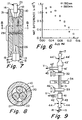
- Fig. 6 is a graph wherein the "NAT Difference", the difference parameter of equation (10), is plotted as a function of ⁇ 2 ⁇ 3 for wavelengths of 1310 nm and 1550 nm.
- Fig. 7 is a cross-sectional view of a capillary tube after optical fibers have been inserted therein.
- Fig. 8 is a cross-sectional view taken along lines 8-8 of Fig. 7.
- Fig. 9 is a schematic illustration of an apparatus for collapsing a capillary tube and stretching the midregion thereof.
- Fig. 10 is a graph illustrating spectral coupling ratio curves for an achromatic 1x2 coupler produced by the method of Example 1.
- Fig. 11 is a theoretical graph illustrating spectral coupling ratio curves for an achromatic 1x3 coupler.
- Fig. 12 is a graph of refractive index plotted as a function of tube radius for one type of tube.
- Fig. 13 shows a fiber optic coupler after it has been drawn down and sealed at its ends.
- the present invention is a specific embodiment of a class of overclad fiber optic couplers that exhibit achromaticity caused by their relatively low value of ⁇ 2 ⁇ 3.
- the theory of operation of such couplers will be discussed in connection with the 2x2 coupler illustrated in Fig. 2.
- optical fibers F1 and F2 are threaded through glass overclad tube O having a diameter d1.
- the refractive index of at least the inner portion of the tube adjacent the fibers is n3.
- Fibers F1 and F2 have a core of refractive index n1 surrounded by cladding of refractive index lower than n1 but greater than n3.
- Tube O is evacuated, and its midregion is heated to collapse it onto the fibers.
- the tube is reheated, and its ends are pulled in opposite directions to stretch the central portion of the collapsed midregion.
- the tube collapse and stretching operations can be performed in accordance with U.S. patent 5,011,251, the teachings of which are incorporated herein by reference.
- the rate at which the two tube ends move away from each other during the stretch step constitutes the combined stretch rate.
- the tube can be stretched at a constant rate, or the stretch rate can vary continuously or in discrete steps.
- the stretching operation can stop after a predetermined coupling is achieved; thereafter, the tube can be reheated, and stretching can occur at a second stretch rate.
- the ratio of the original diameter d1 to the diameter d2 of the central portion of neckdown region N is referred to as the draw ratio R.
- Region N is illustrated as having a constant diameter even though a slight taper exists therein, whereby the longitudinal center of section N exhibits the minimum diameter.
- the coupling characteristics of the resultant coupler are determined by such parameters as the optical and mechanical characteristics of the tube O and fibers F1 and F2 and of the coupler parameters such as length z, neckdown region N, and tapered regions T.
- Optical power can be coupled to an input optical fiber, and the output signals can be monitored to control process steps in the coupler manufacturing process. See, for example, U.S. patent 5,011,251.
- output power was not monitored during stretching.
- the total stretching distance for both stages was usually between 12 and 16 mm.
- the couplers described in that example were therefore initially elongated by some distance within that range.
- the optical characteristics of the resultant device were measured, and the stretching or elongation distance of the subsequently made coupler was adjusted in such a manner as to more nearly achieve the desired characteristics.
- the optimal stretching distance was achieved.
- all couplers of that type were stretched the optimal distance in order to achieve the desired optical characteristics.
- process parameters such as the elongation distance can be fine tuned as a result of optical characterization of the produced couplers.
- ⁇ 1 and ⁇ 2 are the mode fields of the two cores
- r and r' are the radial distances from the center of the cores of fibers F1 and F2, respectively
- n is the index structure of the entire coupler
- n' is the index structure with the core and cladding of F1 replaced by overcladding material of index n3
- the integral is over the entire cross-section of the coupler (but n - n' is only non-zero over the core and cladding of fiber F1).
- the mode fields are assumed to be normalized in this equation, i.e. the integrals ⁇ 12dA and ⁇ 22dA both equal 1.
- Results can be made more quantitative by integrating the coupling equations along the taper. Still more accurate simulations may be done using beam propagation techniques (Fourier transform, finite difference, etc.), although at the cost of much increased computational time.
- beam propagation techniques Frier transform, finite difference, etc.
- the coupled mode model was used to determine the coupling constant for a 2x2 coupler as a function of draw ratio for three different wavelengths in a coupler with a ⁇ 2 ⁇ 3 value of 0.35%. Most of the assumptions which were made concerning coupler parameters are based on work done on standard overclad couplers. Fibers F1 and F2 were assumed to be standard 125 ⁇ m outside diameter single-mode fibers having a core radius of 4 ⁇ m. The core and cladding refractive indices n1 and n2 were assumed to be 1.461000 and 1.455438, respectively. The model was used to generate the graph of Fig. 4, which illustrates the physical mechanism responsible for the improvement in achromaticity of the couplers of the present invention. In Fig.
- the coupling constant is plotted as a function of inverse draw ratio for a parallel core 2x2 coupler. It can be seen that the coupling constant at a given wavelength increases very rapidly with increased draw ratio. However, at very large draw ratios there is a maximum in the curves. This is caused by the fact that eventually the mode field expansion becomes so large that the overlap between the mode fields of the two fibers, in the region consisting of the core and cladding of one of the fibers (which is where the coupling constant overlap integral is taken), actually decreases because of decreasing mode field amplitude. At draw ratios significantly smaller than that at the maximum, the coupling constant at the longer wavelengths is larger because its expansion is larger due to diffractive effects.
- the coupler also includes a region SW (between dashed lines 4 and 5) where the coupling is stronger at shorter wavelengths, thereby compensating for the small draw ratio region. Regions SW and LW pertain to the taper of tube 3b of Fig. 5. The exact value of R MAX must be determined by numerical integration of the coupling equations over the tapered device.
- the propagation constants ( ⁇ ) were calculated for the LP01 and LP02 modes.
- the LP02 mode is the lowest order mode that couples to the LP01 mode in an ideal, matched fiber coupler. From equation (6) and the ⁇ s of the LP01 and LP02 modes, the parameters 1/a
- the difference parameter of equation (7) is plotted as a function of ⁇ 2 ⁇ 3 in Fig. 6 for wavelengths of 1310 and 1550 nm.
- the NAT Difference was calculated for ⁇ 2 ⁇ 3 values from 0.02% to 0.14% at each of the two wavelengths.
- the 1310 nm curve experiences a NAT Difference of zero at a maximum possible theoretical ⁇ 2 ⁇ 3 value of about 0.125%.
- the fiber deformation problem has been substantially diminished by employing the triangular fiber arrangement shown in Figs. 7 and 8.
- coating 23, 24 and 25 is stripped from the ends of coated fibers 17, 18 and 19, respectively, and the ends of the fibers are provided with antireflection terminations as described below.
- Input fiber 20 is inserted into one end of bore 11 of tube 10, and output fibers 21 and 22 are inserted into the other end.
- the fibers are tacked in place by a small amount of epoxy.
- the coupler preform is then placed in the draw chucks, tube 10 is evacuated, and its midregion is heated and collapsed onto the fibers.
- the central portion of the midregion is thereafter drawn down to that diameter and coupling length which is necessary to obtain the desired coupling.
- the fiber cores are thus disposed in a triangular array in the coupling region when viewed in a plane perpendicular to the longitudinal axis of the coupler body.
- the coupler can be drawn to form a tapered region such that the power injected into the input fiber is substantially equally and completely coupled to the two output fibers, thereby generating the substantially parallel insertion loss curves shown in Fig. 10.
- the input fiber core/clad/overclad waveguide must have a propagation constant ⁇ 1CR in the coupling region that is slightly larger than ⁇ 2CR , the propagation constant of each of the two output fiber core/clad/overclad waveguides. This can be accomplished, for example, by doping the cladding of the input fiber with slightly more chlorine than the amount present in the claddings of the output fibers. This technique, which causes the refractive index of the input fiber cladding to be greater than that of the output fiber cladding, is described in US patent 5,011,251.
- This triangular fiber arrangement can also be used to fabricate achromatic 1x3 power splitters. At predetermined wavelengths, one-third of the input power can be caused to remain in the input fiber, which continues on through the coupler and functions as a third output fiber. It is noted that the coating must be stripped from the central region of this input/continuation output fiber, rather than the end thereof. In order to equalize the power in all of the fibers, including the output portion of the input fiber, the input/continuation output fiber must be provided with a propagation constant different from that of the remaining output fibers.
- the ⁇ CR and taper would be chosen so that the insertion loss curves of the two coupled output fibers would be as illustrated by curve 58 of Fig.
- the tube can be formed of silica doped with a small amount of B2O3 (in the range of 0.15 wt.% to 1.0 wt.%).
- B2O3 softens the tube glass relative to the fiber cladding glass, thereby resulting in the formation of couplers having low excess loss.
- the silica tube can contain a sufficient amount of B2O3 to depress the tube refractive index to the level necessary to provide a ⁇ 2 ⁇ 3 value less than 0.125%.
- a further approach is to form the tube from a base glass doped with one or more refractive index-decreasing dopants such as B2O3 and fluorine and one or more refractive index-increasing dopants such as GeO2 and TiO2.
- the combination of the two types of dopants provides a refractive index n3 that results in the desired value of ⁇ 2 ⁇ 3.
- Employing tubes of relatively soft glass enhances to a certain extent the collapsing of the tube onto the fibers; the tube glass flows around the fibers without distorting their shape as much as a harder glass would. Because of the intricate balancing of dopants that is required with this embodiment, it is difficult to implement.
- the overclad tube is preferably made by a vapor deposition technique sometimes referred to as the flame hydrolysis process.
- the tube could also be formed from melted glass or by a sol gel technique.
- Tubes having radial changes in composition have also been employed to make achromatic couplers.
- the inner region of the tube adjacent the tube bore is formed of a composition that provides the desired value of ⁇ 2 ⁇ 3.
- the remainder of the tube can be formed of one or more regions having refractive indices that differ from the inner region.
- the inner region of the tube between the inner surface r is and transition radius r t can contain a small amount of B2O3 to provide a sufficiently low value of ⁇ 2 ⁇ 3 to provide the coupler with achromaticity.
- the outer tube region between r t and the outer surface r o may contain a higher concentration of B2O3 than the inner region.
- Couplers having similar excess losses have been achieved using both substantially constant radial refractive index tubes and tubes having a step decrease in refractive index with radius.
- a disparity in propagation constants between input and output fibers can also be obtained by employing fibers of different diameters.
- FIG. 7-9 A method of making a 1x2 double-window achromatic fiber optic coupler is illustrated in Figs. 7-9.
- Coated fibers 17, 18 and 19 comprised 1.5 meter lengths of 125 ⁇ m diameter single-mode optical fibers 20, 21 and 22 having 250 ⁇ m diameter urethane acrylate coatings 23, 24 and 25, respectively.
- These fibers which were made in accordance with the teachings of U.S. Patent No. 5,011,251, had an 8 ⁇ m diameter core of silica doped with 8.5 wt. % GeO2.
- the cutoff wavelengths of the fibers were below the operating wavelength of the coupler. If, for example, the minimum operating wavelength is 1260 nm, the cutoff wavelengths of the fibers are selected to be between 1200 nm and 1250 nm.
- the aperture was evacuated, and the lower end of the tubular body was heated and drawn to form a 5 mm solid glass rod.
- the rod was severed to form sections, each of which was supported in a lathe where it functioned as a mandrel upon which SiO2 cladding glass particles were deposited to form a final porous preform.
- Final porous optical fiber preforms are conventionally consolidated in a gas mixture containing helium, chlorine and oxygen.
- the amount of chlorine that is employed which is usually that amount that is just sufficient to dry the deposited cladding glass particles, depends upon various parameters including the density of the porous cladding glass coating and the consolidation temperature.
- the final porous preforms of the input fiber and the output fibers were formed and consolidated under such conditions that the chlorine concentration in the input fiber cladding was 0.10 wt. %, and the chlorine concentration in the output fiber cladding was 0.05 wt. %.
- a 6 cm long section of coating was removed from the ends of each length of coated fiber.
- Antireflection terminations 26, 27 and 28 were formed on the end of the fibers by directing a flame at the center of the stripped region of fiber, while the end of the fiber was pulled and severed to form a tapered end.
- the tip of fiber 20 was heated by a burner flame to cause the glass to recede and form a rounded endface, the diameter of which was equal to or slightly smaller than the original uncoated fiber diameter.
- the resultant stripped end regions were about 3.2 cm long.
- Fibers 21 and 22 were inserted through funnel 13 and into bore 11 until the end regions of coatings 24 and 25 were interior to funnel 13, and end 26 was located between midregion 27 and tube end 15.
- Fiber 20 was inserted through funnel 12 and into bore 11 until the end region of coating 23 was interior to funnel 12, and ends 27 and 28 were located between midregion 27 and tube end 14.
- a small amount of UV-curable adhesive (not shown) was applied to fibers 18 and 19 near end 15 to tack them to funnel 13 and to fiber 17 near end 14 to tack it to funnel 12.
- Preform 31 was then inserted through ring burner 34 (Fig. 9) and was clamped to draw chucks 32 and 33.
- the chucks were mounted on motor controlled stages 45 and 46.
- Vacuum attachments 41 and 41' were sealed to the ends of tube 10 as taught in US patent 5,011,251.
- One end of a length of thin rubber tubing 43 was attached to that end of vacuum attachment 41 opposite preform 31; the remaining end of the tubing extending within tube clamping means represented by arrows 44.
- Upper vacuum attachment 41' was similarly associated with tubing 43' and tube clamping means 44'.
- Vacuum V was applied to coupler preform 31 by directing air pressure against tubing 43 and 43' as indicated by arrows 44, 44', thereby clamping the tubing against the fibers extending therethrough.
- ring burner 34 With a vacuum of 46 cm of mercury connected to the tube bore, ring burner 34 was ignited. Flames were generated by supplying gas and oxygen to the burner at rates of 0.55 slpm and 1.10 slpm, respectively. The flame from ring burner 34 heated tube 10 for about 12 seconds, and tube midregion 27 collapsed onto the fibers.
- the vacuum lines were removed, and drops 62 and 63 of adhesive were applied to ends 14 and 15 of the tube.
- the adhesive was cured by exposure to UV light, and the coupler was removed from the chucks.
- spectral insertion loss curves for a coupler made in accordance with Example 1 are shown in Fig. 10. It can be seen that the insertion loss curves of the coupler of this example are relatively flat and are substantially parallel, whereby they exhibit an insertion loss uniformity of 0.24 dB. The excess loss for that device was 0.04 dB and 0.37 dB at 1310 nm and 1550 nm, respectively. Couplers made in accordance with Example 1 exhibited a median excess device loss of about 0.2 dB at 1310 nm. The lowest measured excess loss was 0.04 dB at 1310 nm.
Landscapes
- Physics & Mathematics (AREA)
- General Physics & Mathematics (AREA)
- Optics & Photonics (AREA)
- Manufacture, Treatment Of Glass Fibers (AREA)
- Optical Couplings Of Light Guides (AREA)
Applications Claiming Priority (2)
| Application Number | Priority Date | Filing Date | Title |
|---|---|---|---|
| US999296 | 1992-12-31 | ||
| US07/999,296 US5295210A (en) | 1992-12-31 | 1992-12-31 | Optical waveguide fiber achromatic coupler |
Publications (2)
| Publication Number | Publication Date |
|---|---|
| EP0606583A1 true EP0606583A1 (fr) | 1994-07-20 |
| EP0606583B1 EP0606583B1 (fr) | 1999-08-25 |
Family
ID=25546157
Family Applications (1)
| Application Number | Title | Priority Date | Filing Date |
|---|---|---|---|
| EP93119591A Expired - Lifetime EP0606583B1 (fr) | 1992-12-31 | 1993-12-06 | Coupleur achromatique pour fibres optiques |
Country Status (9)
| Country | Link |
|---|---|
| US (1) | US5295210A (fr) |
| EP (1) | EP0606583B1 (fr) |
| JP (1) | JPH06235841A (fr) |
| KR (1) | KR940015549A (fr) |
| CN (1) | CN1037995C (fr) |
| AU (1) | AU660383B2 (fr) |
| CA (1) | CA2108589A1 (fr) |
| DE (1) | DE69326135T2 (fr) |
| TW (1) | TW261670B (fr) |
Families Citing this family (34)
| Publication number | Priority date | Publication date | Assignee | Title |
|---|---|---|---|---|
| CA2083983A1 (fr) * | 1992-01-27 | 1993-07-28 | Kishor P. Gadkaree | Composition a faible expansion pour l'emballage des coupleurs de guide d'onde optique |
| US5355426A (en) * | 1992-09-02 | 1994-10-11 | Gould Electronics Inc. | Broadband MXN optical fiber couplers and method of making |
| TW291539B (fr) * | 1994-09-30 | 1996-11-21 | Corning Inc | |
| US5594822A (en) * | 1995-12-05 | 1997-01-14 | Corning Incorporated | Fiber optic couplers, preform and method of making same |
| US5644666A (en) * | 1995-12-22 | 1997-07-01 | Gould Electronics Inc. | Broadband optical fiber coupler and method of making |
| US5745626A (en) * | 1996-06-20 | 1998-04-28 | Jds Fitel Inc. | Method for and encapsulation of an optical fiber |
| AU721745B2 (en) * | 1996-12-31 | 2000-07-13 | Corning Incorporated | Optical couplers with multilayer fibers |
| US5987201A (en) * | 1997-02-12 | 1999-11-16 | Applied Fiber Optics, Inc. | Apparatus and method of making a fused dense wavelength-division multiplexer |
| US5889908A (en) * | 1997-07-31 | 1999-03-30 | Corning Incorporated | 1xN fiber optic coupler/splitter |
| US6278821B1 (en) * | 1999-08-13 | 2001-08-21 | Corning Incorporated | Segmented cane mach-zehnder interferometer |
| US6658183B1 (en) * | 2000-10-20 | 2003-12-02 | Lucent Technologies Inc. | Process for fabricating tapered microstructured fiber system and resultant system |
| WO2003040050A1 (fr) * | 2001-10-18 | 2003-05-15 | Research Institute Of Industrial Science & Technology | Preforme destinee a la fabrication d'une virole en verre et procede de fabrication correspondant |
| JP3801933B2 (ja) * | 2002-03-15 | 2006-07-26 | 湖北工業株式会社 | 光学部材の製造方法 |
| US20040050110A1 (en) * | 2002-08-29 | 2004-03-18 | Berkey George E. | Methods for fabricating optical fibers and optical fiber preforms |
| US6834145B2 (en) * | 2002-11-04 | 2004-12-21 | Teem Photonics | 2 to n optical divider with integrated optics |
| EP1660412A2 (fr) * | 2003-07-14 | 2006-05-31 | Massachusetts Institute Of Technology | Fibre optoelectronique coetiree constituee de materiaux conducteurs, semi-conducteurs et isolants |
| WO2008116322A1 (fr) * | 2007-03-28 | 2008-10-02 | Gonthier Francois | Procédé de fusion de fibres optiques dans un boîtier d'épissure |
| JP2008277582A (ja) | 2007-04-27 | 2008-11-13 | Fujikura Ltd | 光ポンピングデバイス用マルチコアファイバとその製造方法、光ポンピングデバイス、ファイバレーザ及びファイバ増幅器 |
| GB2457947B (en) * | 2008-02-29 | 2012-10-17 | Sumitomo Electric Industries | All solid photonic bandgap fibre |
| GB2457946B (en) * | 2008-02-29 | 2011-11-16 | Sumitomo Electric Industries | Method of manufacturing photonic bandgap fibre |
| GB2457948B (en) * | 2008-02-29 | 2012-01-25 | Sumitomo Electric Industries | Photonic bandgap fibre |
| US9063289B1 (en) | 2008-06-30 | 2015-06-23 | Nlight Photonics Corporation | Multimode fiber combiners |
| US9158070B2 (en) | 2008-08-21 | 2015-10-13 | Nlight Photonics Corporation | Active tapers with reduced nonlinearity |
| US8873134B2 (en) | 2008-08-21 | 2014-10-28 | Nlight Photonics Corporation | Hybrid laser amplifier system including active taper |
| US9285541B2 (en) | 2008-08-21 | 2016-03-15 | Nlight Photonics Corporation | UV-green converting fiber laser using active tapers |
| US9494738B1 (en) * | 2009-05-28 | 2016-11-15 | Nlight, Inc. | Single mode fiber combiners |
| CN101950050B (zh) * | 2010-08-13 | 2011-11-30 | 北京交通大学 | 波导数目失配光纤间的熔接方法 |
| DE102012209630A1 (de) * | 2012-06-08 | 2013-12-12 | Jenoptik Laser Gmbh | Faserkoppler |
| US9484706B1 (en) | 2012-06-12 | 2016-11-01 | Nlight, Inc. | Tapered core fiber manufacturing methods |
| WO2014105756A1 (fr) | 2012-12-31 | 2014-07-03 | Nlight Photonics Corporation | Fibre à brillance élevée stable dans l'espace |
| WO2014105757A1 (fr) | 2012-12-31 | 2014-07-03 | Nlight Photonics Corporation | Amplificateur à fibres lma tout en fibres à faible pointage dynamique de forte puissance |
| US11787727B2 (en) * | 2018-04-18 | 2023-10-17 | Lawrence Livermore National Security, Llc | Method for fabrication of sleeveless photonic crystal canes with an arbitrary shape |
| US11061188B1 (en) * | 2020-03-02 | 2021-07-13 | Ad Value Photonics, Inc. | Fiber coupler and method for fabrication of the same |
| US12353016B2 (en) * | 2022-10-10 | 2025-07-08 | Corning Research & Development Corporation | Achromatic couplers, achromatic variable ratio couplers, and methods of making the same |
Citations (6)
| Publication number | Priority date | Publication date | Assignee | Title |
|---|---|---|---|---|
| EP0213829A2 (fr) * | 1985-08-15 | 1987-03-11 | Corning Glass Works | Coupleur pour fibres optiques et sa méthode de fabrication |
| EP0352957A2 (fr) * | 1988-07-25 | 1990-01-31 | Corning Incorporated | Méthode pour la fabrication reproductible des coupleurs optiques |
| US5011251A (en) * | 1989-12-08 | 1991-04-30 | Corning Incorporated | Achromatic fiber optic coupler |
| EP0436182A2 (fr) * | 1990-01-04 | 1991-07-10 | Corning Incorporated | 1xN coupleur à fibre optique et méthode de sa fabrication |
| EP0477459A1 (fr) * | 1990-08-28 | 1992-04-01 | Corning Incorporated | Branchement optique ajustable par rotation |
| US5268979A (en) * | 1992-07-15 | 1993-12-07 | Corning Incorporated | Achromatic overclad fiber optic coupler |
Family Cites Families (6)
| Publication number | Priority date | Publication date | Assignee | Title |
|---|---|---|---|---|
| US4763976A (en) * | 1987-05-21 | 1988-08-16 | Corning Glass Works | Connector employing mode field modification |
| JPH0757592B2 (ja) * | 1988-10-26 | 1995-06-21 | マツダ株式会社 | 自動車のシートベルト装置 |
| IT1232051B (it) * | 1989-03-24 | 1992-01-23 | Cselt Centro Studi Lab Telecom | Dispositivo per la correlazione fra fasci ottici |
| US5044716A (en) * | 1989-12-08 | 1991-09-03 | Corning Incorporated | Chlorine-doped optical component |
| US5175782A (en) * | 1990-11-16 | 1992-12-29 | Amp Incorporated | Optical fiber coupler of improved signal distribution characteristics |
| US5203898A (en) * | 1991-12-16 | 1993-04-20 | Corning Incorporated | Method of making fluorine/boron doped silica tubes |
-
1992
- 1992-12-31 US US07/999,296 patent/US5295210A/en not_active Expired - Lifetime
-
1993
- 1993-10-18 CA CA002108589A patent/CA2108589A1/fr not_active Abandoned
- 1993-12-06 EP EP93119591A patent/EP0606583B1/fr not_active Expired - Lifetime
- 1993-12-06 DE DE69326135T patent/DE69326135T2/de not_active Expired - Fee Related
- 1993-12-20 JP JP5344585A patent/JPH06235841A/ja active Pending
- 1993-12-22 AU AU52634/93A patent/AU660383B2/en not_active Ceased
- 1993-12-23 TW TW082111040A patent/TW261670B/zh active
- 1993-12-30 KR KR1019930031627A patent/KR940015549A/ko not_active Withdrawn
- 1993-12-31 CN CN93112737A patent/CN1037995C/zh not_active Expired - Fee Related
Patent Citations (6)
| Publication number | Priority date | Publication date | Assignee | Title |
|---|---|---|---|---|
| EP0213829A2 (fr) * | 1985-08-15 | 1987-03-11 | Corning Glass Works | Coupleur pour fibres optiques et sa méthode de fabrication |
| EP0352957A2 (fr) * | 1988-07-25 | 1990-01-31 | Corning Incorporated | Méthode pour la fabrication reproductible des coupleurs optiques |
| US5011251A (en) * | 1989-12-08 | 1991-04-30 | Corning Incorporated | Achromatic fiber optic coupler |
| EP0436182A2 (fr) * | 1990-01-04 | 1991-07-10 | Corning Incorporated | 1xN coupleur à fibre optique et méthode de sa fabrication |
| EP0477459A1 (fr) * | 1990-08-28 | 1992-04-01 | Corning Incorporated | Branchement optique ajustable par rotation |
| US5268979A (en) * | 1992-07-15 | 1993-12-07 | Corning Incorporated | Achromatic overclad fiber optic coupler |
Also Published As
| Publication number | Publication date |
|---|---|
| AU660383B2 (en) | 1995-06-22 |
| CA2108589A1 (fr) | 1994-07-01 |
| KR940015549A (ko) | 1994-07-21 |
| DE69326135T2 (de) | 2000-05-25 |
| AU5263493A (en) | 1994-07-14 |
| JPH06235841A (ja) | 1994-08-23 |
| TW261670B (fr) | 1995-11-01 |
| CN1037995C (zh) | 1998-04-08 |
| US5295210A (en) | 1994-03-15 |
| EP0606583B1 (fr) | 1999-08-25 |
| DE69326135D1 (de) | 1999-09-30 |
| CN1090057A (zh) | 1994-07-27 |
Similar Documents
| Publication | Publication Date | Title |
|---|---|---|
| EP0606583B1 (fr) | Coupleur achromatique pour fibres optiques | |
| EP0578982B1 (fr) | Coupleur à fibres optiques achtomatique et revêtu | |
| EP0431311B1 (fr) | Coupleur à fibre optique achromatique et son procédé de fabrication | |
| EP0618478B1 (fr) | Mach-Zehnder monolithique | |
| EP0409447B1 (fr) | Méthode de fabrication d'un coupleur de fibres optiques | |
| US6272268B1 (en) | Optical couplers with multilayer fibers | |
| EP0432421B1 (fr) | Composant optique dopé en chlorine | |
| US5339372A (en) | Low loss coupler | |
| EP0607570B1 (fr) | Coupleur et amplificateur à fibres optiques | |
| WO1998029768A9 (fr) | Coupleurs optiques a fibres multicouches | |
| US5754720A (en) | Low loss fiber optic coupler and method | |
| EP0681196A1 (fr) | Coupleur à fibres optiques à faibles pertes non-adiabatiques | |
| HK22097A (en) | Method of making fiber optic couplers |
Legal Events
| Date | Code | Title | Description |
|---|---|---|---|
| PUAI | Public reference made under article 153(3) epc to a published international application that has entered the european phase |
Free format text: ORIGINAL CODE: 0009012 |
|
| AK | Designated contracting states |
Kind code of ref document: A1 Designated state(s): DE FR GB IT NL |
|
| 17P | Request for examination filed |
Effective date: 19941229 |
|
| 17Q | First examination report despatched |
Effective date: 19960724 |
|
| GRAG | Despatch of communication of intention to grant |
Free format text: ORIGINAL CODE: EPIDOS AGRA |
|
| GRAG | Despatch of communication of intention to grant |
Free format text: ORIGINAL CODE: EPIDOS AGRA |
|
| GRAH | Despatch of communication of intention to grant a patent |
Free format text: ORIGINAL CODE: EPIDOS IGRA |
|
| GRAH | Despatch of communication of intention to grant a patent |
Free format text: ORIGINAL CODE: EPIDOS IGRA |
|
| GRAA | (expected) grant |
Free format text: ORIGINAL CODE: 0009210 |
|
| AK | Designated contracting states |
Kind code of ref document: B1 Designated state(s): DE FR GB IT NL |
|
| REF | Corresponds to: |
Ref document number: 69326135 Country of ref document: DE Date of ref document: 19990930 |
|
| ITF | It: translation for a ep patent filed | ||
| ET | Fr: translation filed | ||
| PLBE | No opposition filed within time limit |
Free format text: ORIGINAL CODE: 0009261 |
|
| STAA | Information on the status of an ep patent application or granted ep patent |
Free format text: STATUS: NO OPPOSITION FILED WITHIN TIME LIMIT |
|
| 26N | No opposition filed | ||
| PGFP | Annual fee paid to national office [announced via postgrant information from national office to epo] |
Ref country code: NL Payment date: 20010921 Year of fee payment: 9 |
|
| PGFP | Annual fee paid to national office [announced via postgrant information from national office to epo] |
Ref country code: GB Payment date: 20011102 Year of fee payment: 9 |
|
| PGFP | Annual fee paid to national office [announced via postgrant information from national office to epo] |
Ref country code: FR Payment date: 20011203 Year of fee payment: 9 |
|
| PGFP | Annual fee paid to national office [announced via postgrant information from national office to epo] |
Ref country code: DE Payment date: 20011228 Year of fee payment: 9 |
|
| REG | Reference to a national code |
Ref country code: GB Ref legal event code: IF02 |
|
| PG25 | Lapsed in a contracting state [announced via postgrant information from national office to epo] |
Ref country code: GB Free format text: LAPSE BECAUSE OF NON-PAYMENT OF DUE FEES Effective date: 20021206 |
|
| PG25 | Lapsed in a contracting state [announced via postgrant information from national office to epo] |
Ref country code: NL Free format text: LAPSE BECAUSE OF NON-PAYMENT OF DUE FEES Effective date: 20030701 Ref country code: DE Free format text: LAPSE BECAUSE OF NON-PAYMENT OF DUE FEES Effective date: 20030701 |
|
| GBPC | Gb: european patent ceased through non-payment of renewal fee | ||
| NLV4 | Nl: lapsed or anulled due to non-payment of the annual fee |
Effective date: 20030701 |
|
| PG25 | Lapsed in a contracting state [announced via postgrant information from national office to epo] |
Ref country code: FR Free format text: LAPSE BECAUSE OF NON-PAYMENT OF DUE FEES Effective date: 20030901 |
|
| REG | Reference to a national code |
Ref country code: FR Ref legal event code: ST |
|
| PG25 | Lapsed in a contracting state [announced via postgrant information from national office to epo] |
Ref country code: IT Free format text: LAPSE BECAUSE OF NON-PAYMENT OF DUE FEES;WARNING: LAPSES OF ITALIAN PATENTS WITH EFFECTIVE DATE BEFORE 2007 MAY HAVE OCCURRED AT ANY TIME BEFORE 2007. THE CORRECT EFFECTIVE DATE MAY BE DIFFERENT FROM THE ONE RECORDED. Effective date: 20051206 |