EP0606584B1 - Palier pour un cylindre de clichés équipé d'un tube enfilable - Google Patents
Palier pour un cylindre de clichés équipé d'un tube enfilable Download PDFInfo
- Publication number
- EP0606584B1 EP0606584B1 EP93119622A EP93119622A EP0606584B1 EP 0606584 B1 EP0606584 B1 EP 0606584B1 EP 93119622 A EP93119622 A EP 93119622A EP 93119622 A EP93119622 A EP 93119622A EP 0606584 B1 EP0606584 B1 EP 0606584B1
- Authority
- EP
- European Patent Office
- Prior art keywords
- bearing according
- printing cylinder
- rollers
- bearing
- iii
- Prior art date
- Legal status (The legal status is an assumption and is not a legal conclusion. Google has not performed a legal analysis and makes no representation as to the accuracy of the status listed.)
- Expired - Lifetime
Links
- 239000003822 epoxy resin Substances 0.000 claims description 2
- 229910001092 metal group alloy Inorganic materials 0.000 claims description 2
- 239000011368 organic material Substances 0.000 claims description 2
- 229920000647 polyepoxide Polymers 0.000 claims description 2
- 229910003480 inorganic solid Inorganic materials 0.000 claims 1
- 239000011343 solid material Substances 0.000 claims 1
- 238000004519 manufacturing process Methods 0.000 description 6
- 238000003860 storage Methods 0.000 description 3
- 241000209035 Ilex Species 0.000 description 2
- 230000002349 favourable effect Effects 0.000 description 2
- 239000000463 material Substances 0.000 description 2
- 230000004308 accommodation Effects 0.000 description 1
- 230000005540 biological transmission Effects 0.000 description 1
- 239000000919 ceramic Substances 0.000 description 1
- 230000008878 coupling Effects 0.000 description 1
- 238000010168 coupling process Methods 0.000 description 1
- 238000005859 coupling reaction Methods 0.000 description 1
- 238000009826 distribution Methods 0.000 description 1
- 238000009510 drug design Methods 0.000 description 1
- 238000005457 optimization Methods 0.000 description 1
Images




Classifications
-
- B—PERFORMING OPERATIONS; TRANSPORTING
- B41—PRINTING; LINING MACHINES; TYPEWRITERS; STAMPS
- B41F—PRINTING MACHINES OR PRESSES
- B41F13/00—Common details of rotary presses or machines
- B41F13/08—Cylinders
- B41F13/24—Cylinder-tripping devices; Cylinder-impression adjustments
- B41F13/26—Arrangement of cylinder bearings
Definitions
- the invention relates to a bearing for a pressure cylinder equipped with a slide-on sleeve.
- a bearing for a printing cylinder (DE-PS 37 15 536) is known, in which a jaw chuck is arranged displaceably on the printing unit side wall, in which a bearing seated on the journal of the printing cylinder is held in the operating state and can be moved apart and through via the diameter of the sleeve adjustable stops in the holding position for the printing cylinder is adjustable.
- the expandable jaw chuck including the necessary drive mechanism, requires a relatively large amount of space in the radial direction of the printing cylinder, which is however only available to a very limited extent in a multi-cylinder arrangement in a printing unit.
- the straight guides for the jaws require a relatively high manufacturing effort.
- the pins of a rubber cylinder are supported directly or indirectly with three rollers, which are mounted on eccentric bolts. By moving two such support points away, the possibility of parking the cylinder is given in the released directions.
- the invention has for its object to provide a storage for a slide cylinder equipped printing cylinder according to the preamble of claim 1, which enables easy to manufacture, space-saving means a sleeve change in the rotary printing press and a reliable, adjustable support of the printing cylinder in the Operating condition guaranteed.
- rollers which serve both to support and to support the printing cylinder, permit simple journalless mounting of the printing cylinder.
- rollers By executing one of the side walls of the recesses as an insertable cover segment according to claim 3, the rollers can be easily installed.
- rollers allow the rollers to be arranged on the side of the frame if the cutouts cannot be arranged in the latter for design and production reasons or if a rotary printing press is retrofitted with sleeve-equipped printing cylinders.
- the continuous ring groove according to claim 6 is particularly easy to manufacture.
- the embodiment mentioned in claim 9 allows an effective adjustment of the eccentric bolts with few transmission elements in a narrow space and can therefore be used advantageously in a multi-cylinder arrangement in a printing unit.
- the adjustable stop according to claim 10 and in a special embodiment according to claim 11 allows an easy adjustment of the rollers in the operating state depending on the pressure cylinder position.
- Claims 12 and 13 favor centering of the sleeve when pushed onto the pressure cylinder.
- race ring according to claims 14 to 17 allows it to be optimized independently of the other cylinder body of the impression cylinder with regard to its use as a running surface for the rollers.
- Claim 20 allows a particularly rational design of the rollers as roller bearings.
- the individual adjustability of the eccentric bolt causing a pivoting of the rollers allows u. a. an optimal setting for the respective load condition of the printing cylinder.
- the two most stressed roles should be switched on and off at the same time and in opposite directions.
- the solution according to claim 22 enables different positions of the printing cylinder to be realized via a corresponding radial adjustment of the rollers supporting it.
- Claim 24 contains a cheap drive variant for adjusting the eccentric bolt.
- Claims 25 to 27 contain optimized embodiments for adjusting the eccentric bolts with regard to the maximum load on the rollers.
- Fig. 1 shows the side view of from in a frame wall 1 eccentric bolt mounted on a rotary printing press 2 rotatably arranged rollers 3 circumferentially supported printing cylinder 4.
- the rollers 3 are each arranged in a pocket-shaped recess 5 of the frame wall 1, and the eccentric bolts 2 are mounted on the one hand in a wall 6 of the frame wall 1 delimiting the recess 5 and on the other hand in a cover segment 7 firmly inserted in the latter (FIG. 3) and with an axle 8 outside the frame wall 1 connected to a lever 9, on which a pressure medium-operated, working cylinder 10 is pivotally mounted in the frame wall 1 (Fig. 1).
- the pivoting movement of the lever 9 is limited in the direction causing the rollers 3 to press against the pressure cylinder 4 by in each case a stop 13 consisting of a body 12 fastened to the frame wall 1 and penetrated by a set screw 11 serving as a system in a threaded bore (FIG. 1).
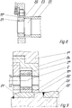
- Fig. 2 shows a pressure cylinder 4 with a slide-on sleeve 14.
- the rollers 3 are pivoted by rotating the eccentric bolts 2 from the pressure cylinder 4 additionally supported on the opposite side, not shown, so that the opening in the frame wall 1 in the form of a compared to the outer diameter of the sleeve 14 enlarged wall bore 15 is exposed.
- the pressure cylinder 4 is equipped with a run-up bevel 16 on the end for circumferential pushing on of the sleeve 14 and on this side with a running surface 17 for the rollers 3 which is set back relative to the inner diameter of the sleeve 14.
- FIGS. 4 and 5 show a ring 18, which is equipped with pocket-shaped recesses 5 I for the rollers 3 I and is laterally attached to the frame wall 1 I while leaving its opening open.
- 6 and 7 show a segment 19 which is separately attached laterally to the frame wall 1 II while leaving its opening, each with a pocket-shaped recess 5 II for a roller 3 II .
- the pocket-shaped recesses 5; 5 I ; 1 to 4 can also each by an easy to manufacture, all roles 3; 3 I ; detecting, to the wall hole 15 open, continuous ring groove are replaced.
- the tread 17; 17 I ; 17 II for roles 3; 3 I ; 3 II can either be hardened using a suitable material or coated with an additional wear layer made of metallic alloys or non-metallic hard materials, for example made of ceramic. Possibly. this wear layer can also be sealed with organic materials based on epoxy resin.
- rollers 3 III With regard to a completely mountable assembly, it is expedient to store the rollers 3 III with the eccentric bolts 2 I in a wall socket 24 which is inserted coaxially to the pressure cylinder into the frame wall 1 III and which has a smallest inside diameter which enables the sleeve change and is screwed to the frame wall 1 III .
- the rollers 27; 28 arranged in the area of the maximum load at a shorter distance and synchronously adjustably connected to one another by a coupling gear 29, so that only one eccentric bolt 30 has to be equipped with a drive consisting of worm drives 31 and a servomotor.
- the little-loaded third roller 32 which is indispensable for precise guidance of the pressure cylinder 4 II , is compared with the other two rollers 27; 28 first off and last employed.
- the pressure medium for the working cylinder 33 is advantageously adjustable and the adjustment path for the eccentric bolt 34 is not limited by stops.
- FIG. 12 shows a variant of FIG. 10, in which the servomotors 26 I for the individual eccentric bolts 2 III each use sensors 35 that fix the position for pressure on and off and the change of the sleeve of the pressure cylinder; 36; 37 can be controlled.
- the servomotors can also be movable against stops that fix the position for printing on and off and the change of the sleeve of the printing cylinder, but the middle stop for the pressure shutdown must be pivotable away.
Landscapes
- Engineering & Computer Science (AREA)
- Mechanical Engineering (AREA)
- Rotary Presses (AREA)
- Rolls And Other Rotary Bodies (AREA)
- Reduction Rolling/Reduction Stand/Operation Of Reduction Machine (AREA)
- Inking, Control Or Cleaning Of Printing Machines (AREA)
Claims (29)
- Support pour un cylindre d'impression (4; 4I) équipé d'une douille emmanchable dans une presse rotative, le support possédant au moins trois corps d'appui pouvant être déplacés à partir de la zone d'une ouverture (15), qui permet le remplacement de la douille, de la paroi (1 à 1III) d'un bâti et par rapport à la position devant être obtenue du cylindre d'impression, et contre lesquels le cylindre d'impression prend appui radialement latéralement en fonctionnement, caractérisé en ce que les corps d'appui sont agencés chacun sous la forme d'un rouleau (3 à 3III) monté rotatif sur un axe d'excentrique (2 à 2III) monté dans la paroi (1 à 1III) du bâti, parallèlement à l'axe du cylindre d'impression (4; 4I), ces rouleaux soutenant le cylindre d'impression (4; 4I) sur une surface circonférentielle de roulement, à l'extérieur de l'appui pour la douille (14).
- Support selon la revendication 1, caractérisé en ce que les rouleaux (3) sont disposés chacun dans un évidement en forme de poche (5) de la paroi (1) du bâti.
- Support selon la revendication 2, caractérisé en ce que respectivement l'une des parois, qui limitent latéralement les évidements, est agencée sous la forme d'un segment de recouvrement (7) pouvant être inséré de façon fixe dans la paroi (1) du bâti.
- Support selon la revendication 1, caractérisé en ce que les rouleaux (3I) sont disposés respectivement dans des évidements en forme de poches (5I) d'un anneau (18) qui est monté latéralement de façon fixe sur la paroi (1I) du bâti, tout en laissant subsister l'ouverture de cette paroi.
- Support selon la revendication 1, caractérisé en ce que les rouleaux (3II) sont disposés respectivement dans un évidement en forme de poche (5II) d'un segment (19) monté latéralement séparément, de façon fixe, sur la paroi (1III) du bâti, tout en laissant subsister l'ouverture de ce dernier.
- Support selon les revendications 2 à 4, caractérisé en ce que les évidements en forme de poches (5; 5I) sont agencés sous la forme d'une gorge annulaire continue, qui loge tous les rouleaux (3; 3I).
- Support selon les revendications 2 à 6, caractérisé en ce que les axes d'excentriques sont montés respectivement dans les parois latérales (6) des évidements en forme de poches (5) ou dans la gorge annulaire ou dans un segment de recouvrement (7) inséré dans respectivement une paroi.
- Support selon la revendication 1, caractérisé en ce que les rouleaux (3III) sont tourillonnés dans un coussinet de paroi (24) qui est monté de façon fixe coaxialement au cylindre d'impression dans la paroi (1I) du bâti et possède le plus faible diamètre intérieur permettant le remplacement de la douille.
- Support selon la revendication 1, caractérisé en ce que le tourillon (8) de l'axe d'excentrique (2) est attaqué par un levier (9), auquel est articulé un vérin de travail (10), qui est relié à pouvoir faire basculer la paroi (1) du boitier et est entrainé par un fluide sous pression.
- Support selon la revendication 9, caractérisé en ce que le mouvement de basculement du levier (9) est limité par une butée réglable (13), qui est reliée à la paroi (1) du boîtier.
- Support selon la revendication 10, caractérisé en ce que la butée (13) est constituée par un corps (12) qui est traversé par une vis de réglage (11), utilisée comme élément d'application pour le levier (9), dans un perçage taraudé, et qui est fixé à la paroi (1) du bâti.
- Support selon la revendication 1, caractérisé en ce que la surface de roulement (17) du cylindre d'impression (4) possède un diamètre extérieur qui est inférieur au diamètre intérieur de la douille (14) et provoque un centrage de cette douille lors de l'emmanchement sur le cylindre d'impression (4).
- Support selon la revendication 12, caractérisé en ce que la surface de roulement (17) comporte, sur la face frontale du cylindre d'impression (4), une rampe de montée (16).
- Support selon la revendication 1, caractérisé en ce que la surface de roulement (17I; 17II) pour les rouleaux (3III) est située sur une bague de roulement (20; 20I) reliée rigidement au cylindre d'impression.
- Support selon la revendication 14, caractérisé en ce que la bague de roulement (20) est disposée sur une partie étagée à symétrie de révolution (21) d'un fond (23) inséré latéralement dans un tube envelope (22) du cylindre d'impression.
- Support selon la revendication 15, caractérisé en ce que la bague de roulement (20) est fixée au fond (23).
- Support selon la revendication 15, caractérisé en ce que la bague de roulement (20I) est emmanchée à force sur la partie étagée (21I) du fond (23I).
- Support selon la revendication 1, caractérisé en ce que la surface de roulement (17 à 17II) pour les rouleaux (3 à 3III) est trempée.
- Support selon la revendication 1, caractérisé en ce que la surface de roulement (17 à 17II) est recouverte d'une couche d'usure supplémentaire formée par des alliages métalliques ou par des substances dures minérales non métalliques et est en outre éventuellement scellée avec des matériaux organiques à base de résine époxy.
- Support selon la revendication 1, caractérisé en ce que les rouleaux (3 à 3III) sont réalisés chacun sous la forme d'un roulement dont la piste extérieure agit en tant que surface de roulement.
- Support selon la revendication 1, caractérisé en ce que les axes d'excentrique (2 à 2III) sont décalés latéralement les uns par rapport aux autres et/ou sont déplaçables individuellement en partie en des sens opposés.
- Support selon la revendication 1, caractérisé en ce que les axes d'excentrique (2 à 2III) peuvent être déplacés individuellement en étant commandés par un moteur, par voie électronique, le cas échéant par un ordinateur, et ce en fonction de la position du cylindre d'impression.
- Support selon la revendication 1, caractérisé en ce que les rouleaux (27; 28) sont disposés de façon dissymétrique par rapport à la périphérie du cylindre d'impression (4I), en étant situés à une distance plus faible dans la direction de la charge maximale.
- Support selon la revendication 1, caractérisé en ce que les axes d'excentriques (2II; 2III) sont reliés respectivement par l'intermédiaire d'un engrenage à vis sans fin (25; 25I) à un servomoteur commandable (26; 26I).
- Support selon la revendication 1, caractérisé en ce que les axes d'excentriques des rouleaux (27,28), qui supportent le cylindre d'impression dans la zone de la charge maximale, sont déplaçables d'une manière synchrone et que le boulon d'excentrique (34) du rouleau (32), qui guide simplement le cylindre d'impression, est déplaçable individuellement.
- Support selon la revendication 25, caractérisé en ce que les deux axes d'excentriques déplaçables d'une manière synchrone sont reliés par une transmission de couplage (29) entre eux, et l'un de ces axes d'excentriques (30) est en outre relié par l'intermédiaire d'un engrenage à vis sans fin (31) à un servomoteur commandable.
- Support selon la revendication 25, caractérisé en ce que l'axe d'excentrique (34) du rouleau (32) qui guide simplement le cylindre d'impression (4I), est relié par l'intermédiaire d'un levier à un cylindre de travail (33) entraîné par des moyens de pression réglable.
- Support selon la revendication 24, caractérisé en ce que les servomoteurs (26I) sont commandés respectivement à l'aide de capteurs (35;36;37), qui bloquent la position de l'axe d'excentrique respectif (2III) pour l'application ou la suppression d'une pression et le remplacement de la douille du cylindre d'impression.
- Support selon la revendication 24, caractérisé en ce que les servomoteurs (26I) peuvent être déplacés respectivement en direction de la position de l'axe d'excentrique respectif (2III) pour l'application et la suppression d'une pression et le remplacement de la douille du cylindre d'impression, la butée médiane pouvant être écartée par basculement pour la suppression de la pression.
Applications Claiming Priority (2)
| Application Number | Priority Date | Filing Date | Title |
|---|---|---|---|
| DE4241566A DE4241566A1 (de) | 1992-12-10 | 1992-12-10 | Lagerung für einen mit einer aufschiebbaren Hülse ausgestatteten Druckzylinder |
| DE4241566 | 1992-12-10 |
Publications (2)
| Publication Number | Publication Date |
|---|---|
| EP0606584A1 EP0606584A1 (fr) | 1994-07-20 |
| EP0606584B1 true EP0606584B1 (fr) | 1996-03-13 |
Family
ID=6474852
Family Applications (1)
| Application Number | Title | Priority Date | Filing Date |
|---|---|---|---|
| EP93119622A Expired - Lifetime EP0606584B1 (fr) | 1992-12-10 | 1993-12-06 | Palier pour un cylindre de clichés équipé d'un tube enfilable |
Country Status (4)
| Country | Link |
|---|---|
| US (1) | US5392709A (fr) |
| EP (1) | EP0606584B1 (fr) |
| JP (1) | JPH06210821A (fr) |
| DE (2) | DE4241566A1 (fr) |
Families Citing this family (8)
| Publication number | Priority date | Publication date | Assignee | Title |
|---|---|---|---|---|
| US5808439A (en) * | 1996-12-20 | 1998-09-15 | Spanenberg; Peter E. | Satellite small angle tilting mechanism |
| NL1005525C2 (nl) | 1997-03-13 | 1998-09-15 | Multi Print Systems M P S B V | Drukmachine met verwisselbare inktopbrengmiddelen. |
| EP0980312B1 (fr) * | 1997-05-05 | 2002-07-31 | Koenig & Bauer Aktiengesellschaft | Palier pour cylindre de rotative |
| US5943955A (en) | 1997-08-29 | 1999-08-31 | Goss Graphic Systems, Inc. | Printing press having cantilevered self-driven cylinders |
| NL1021417C2 (nl) * | 2002-09-09 | 2004-03-10 | Stork Prints Bv | Drukcilinderondersteuningseenheid. |
| NL1021874C2 (nl) * | 2002-11-08 | 2004-05-11 | Stork Prints Bv | Drukcilinderondersteuningseenheid met steunring. |
| NL1026736C2 (nl) * | 2004-07-28 | 2006-01-31 | Stork Prints Bv | Drukcilinderondersteuningseenheid, positioneerelement, drukcilinder voorzien van positioneerelement, drukmachine voorzien van drukcilinderondersteuningseenheid, en gebruik hiervan. |
| NL2002915C2 (en) * | 2009-05-22 | 2010-11-23 | Mps Holding B V | PRINTING MODULE AND PRINTING MACHINE PROVIDED WITH SUCH A PRINTING MODULE. |
Family Cites Families (5)
| Publication number | Priority date | Publication date | Assignee | Title |
|---|---|---|---|---|
| DE1236529B (de) * | 1964-10-14 | 1967-03-16 | Schnellressenfab Heidelberg | Vorrichtung zur Lagerung sowie zum An- und Abstellen des mittleren Zylinders eines Dreizylinderdruckwerks |
| US3618516A (en) * | 1969-08-04 | 1971-11-09 | Adamovske Strojirny Np | Support for offset cylinders of printing machines |
| DE3715536A1 (de) * | 1987-05-09 | 1988-12-01 | Roland Man Druckmasch | Lagerung fuer einen druckwerkzylinder |
| DE9110806U1 (de) * | 1991-08-31 | 1991-10-17 | Heidelberger Druckmaschinen Ag, 6900 Heidelberg | Vorrichtung zum Einstellen von Auftragwalzen am Plattenzylinder von Rotationsdruckmaschinen |
| DE9115598U1 (de) * | 1991-09-09 | 1992-04-23 | Koenig & Bauer AG, 8700 Würzburg | Anordnung zum Einstellen von Exzenterbuchsen für Zylinder von Druckmaschinen |
-
1992
- 1992-12-10 DE DE4241566A patent/DE4241566A1/de not_active Withdrawn
-
1993
- 1993-12-06 DE DE59301898T patent/DE59301898D1/de not_active Expired - Fee Related
- 1993-12-06 EP EP93119622A patent/EP0606584B1/fr not_active Expired - Lifetime
- 1993-12-07 JP JP5306349A patent/JPH06210821A/ja active Pending
- 1993-12-08 US US08/163,821 patent/US5392709A/en not_active Expired - Fee Related
Also Published As
| Publication number | Publication date |
|---|---|
| US5392709A (en) | 1995-02-28 |
| DE59301898D1 (de) | 1996-04-18 |
| JPH06210821A (ja) | 1994-08-02 |
| EP0606584A1 (fr) | 1994-07-20 |
| DE4241566A1 (de) | 1994-06-16 |
Similar Documents
| Publication | Publication Date | Title |
|---|---|---|
| EP0232730B1 (fr) | Dispositif de fixation d'un cliché souple sur le cylindre porte-cliché d'une rotative | |
| EP0813959B1 (fr) | Cylindre entraíné | |
| EP0425936B1 (fr) | Dispositif pour le repérage, la fixation et la tension rapides de plaques d'impression | |
| EP0769373B1 (fr) | Dispositif de changement des manchons de cylindres d'imprimerie dans les machines à imprimer | |
| EP0606584B1 (fr) | Palier pour un cylindre de clichés équipé d'un tube enfilable | |
| EP0602429B1 (fr) | Palier pour un cylindre d'imprimerie muni d'un manchon enfilable | |
| EP0087625A1 (fr) | Dispositif pour l'application des rouleaux toucheurs sur le cylindre porte-plaque des machines d'impression et pour l'enlèvement et le réglage de ces rouleaux | |
| EP1155829A2 (fr) | Elément de cylindre interchangeable dans une unité d'impression électrographique | |
| DE60031639T2 (de) | Offsetdruckwerk | |
| EP1310360B1 (fr) | Machine d'impression flexographique avec des cylindres de transfert d'encre applicables de façon manuelle et automatique | |
| DE2130278B2 (de) | Druckeinheit einer Rollenrotationsdruckmaschine zum wahlweisen Hoch- oder Flachdruck | |
| DE4400563C2 (de) | Walze in einem Farbwerk oder Feuchtwerk einer Rotationsdruckmaschine | |
| EP0125670B1 (fr) | Dispositif pour imprimer | |
| EP0741018B1 (fr) | Dispositif pour le placement d'un rouleau d'application | |
| DE1003760B (de) | Walzensupport fuer das Lagern von Farbwerkwalzen an Buchdruck-, Offsetdruck- u. dgl.Maschinen | |
| DE515547C (de) | Vorrichtung zum Einstellen der Formzylinder in deren Umfangsrichtung und Laengsrichtung bei den Rotationsdruckwerken | |
| EP0013746B1 (fr) | Dispositif de serrage de pièces à usiner | |
| EP0353652B1 (fr) | Dispositif supplémentaire pour montage sur une machine d'impression offset | |
| EP0384127B1 (fr) | Dispositif de réglage du registre circonférentiel dans une imprimerie rotative à feuilles | |
| DE19833113A1 (de) | Lagerung für einen Zylinder in einer Druckmaschine | |
| DE4139326C2 (de) | Vorrichtung zum Einstellen des Umfangsregisters an Rotationsdruckmaschinen | |
| EP0949070B1 (fr) | Palier pour un cylindre dans une machine d'impression | |
| EP1707361B1 (fr) | Rouleau applicateur pour un groupe d'impression offset | |
| CH687603A5 (de) | Anordnung zum Einstellen des Lagerspiels bei Zylindern von Druckmaschinen. | |
| DE10123324C1 (de) | Schutzvorrichtung eines Zylinders einer Druckmaschine |
Legal Events
| Date | Code | Title | Description |
|---|---|---|---|
| PUAI | Public reference made under article 153(3) epc to a published international application that has entered the european phase |
Free format text: ORIGINAL CODE: 0009012 |
|
| AK | Designated contracting states |
Kind code of ref document: A1 Designated state(s): CH DE FR GB IT LI SE |
|
| 17P | Request for examination filed |
Effective date: 19940723 |
|
| 17Q | First examination report despatched |
Effective date: 19941027 |
|
| ITF | It: translation for a ep patent filed | ||
| GRAA | (expected) grant |
Free format text: ORIGINAL CODE: 0009210 |
|
| AK | Designated contracting states |
Kind code of ref document: B1 Designated state(s): CH DE FR GB IT LI SE |
|
| REF | Corresponds to: |
Ref document number: 59301898 Country of ref document: DE Date of ref document: 19960418 |
|
| ET | Fr: translation filed | ||
| GBT | Gb: translation of ep patent filed (gb section 77(6)(a)/1977) |
Effective date: 19960621 |
|
| PLBE | No opposition filed within time limit |
Free format text: ORIGINAL CODE: 0009261 |
|
| STAA | Information on the status of an ep patent application or granted ep patent |
Free format text: STATUS: NO OPPOSITION FILED WITHIN TIME LIMIT |
|
| 26N | No opposition filed | ||
| PGFP | Annual fee paid to national office [announced via postgrant information from national office to epo] |
Ref country code: GB Payment date: 19991112 Year of fee payment: 7 |
|
| PGFP | Annual fee paid to national office [announced via postgrant information from national office to epo] |
Ref country code: CH Payment date: 19991115 Year of fee payment: 7 |
|
| PGFP | Annual fee paid to national office [announced via postgrant information from national office to epo] |
Ref country code: FR Payment date: 19991123 Year of fee payment: 7 Ref country code: DE Payment date: 19991123 Year of fee payment: 7 |
|
| PGFP | Annual fee paid to national office [announced via postgrant information from national office to epo] |
Ref country code: SE Payment date: 19991125 Year of fee payment: 7 |
|
| PG25 | Lapsed in a contracting state [announced via postgrant information from national office to epo] |
Ref country code: GB Free format text: LAPSE BECAUSE OF NON-PAYMENT OF DUE FEES Effective date: 20001206 |
|
| PG25 | Lapsed in a contracting state [announced via postgrant information from national office to epo] |
Ref country code: SE Free format text: LAPSE BECAUSE OF NON-PAYMENT OF DUE FEES Effective date: 20001207 |
|
| PG25 | Lapsed in a contracting state [announced via postgrant information from national office to epo] |
Ref country code: LI Free format text: LAPSE BECAUSE OF NON-PAYMENT OF DUE FEES Effective date: 20001231 Ref country code: CH Free format text: LAPSE BECAUSE OF NON-PAYMENT OF DUE FEES Effective date: 20001231 |
|
| GBPC | Gb: european patent ceased through non-payment of renewal fee |
Effective date: 20001206 |
|
| EUG | Se: european patent has lapsed |
Ref document number: 93119622.4 |
|
| PG25 | Lapsed in a contracting state [announced via postgrant information from national office to epo] |
Ref country code: FR Free format text: LAPSE BECAUSE OF NON-PAYMENT OF DUE FEES Effective date: 20010831 |
|
| REG | Reference to a national code |
Ref country code: FR Ref legal event code: ST |
|
| PG25 | Lapsed in a contracting state [announced via postgrant information from national office to epo] |
Ref country code: DE Free format text: LAPSE BECAUSE OF NON-PAYMENT OF DUE FEES Effective date: 20011002 |
|
| PG25 | Lapsed in a contracting state [announced via postgrant information from national office to epo] |
Ref country code: IT Free format text: LAPSE BECAUSE OF NON-PAYMENT OF DUE FEES;WARNING: LAPSES OF ITALIAN PATENTS WITH EFFECTIVE DATE BEFORE 2007 MAY HAVE OCCURRED AT ANY TIME BEFORE 2007. THE CORRECT EFFECTIVE DATE MAY BE DIFFERENT FROM THE ONE RECORDED. Effective date: 20051206 |
|
| REG | Reference to a national code |
Ref country code: CH Ref legal event code: PL Ref country code: CH Ref legal event code: EP |