EP0606701B1 - Statische und dynamische integrierte Kompandierung - Google Patents
Statische und dynamische integrierte Kompandierung Download PDFInfo
- Publication number
- EP0606701B1 EP0606701B1 EP93307175A EP93307175A EP0606701B1 EP 0606701 B1 EP0606701 B1 EP 0606701B1 EP 93307175 A EP93307175 A EP 93307175A EP 93307175 A EP93307175 A EP 93307175A EP 0606701 B1 EP0606701 B1 EP 0606701B1
- Authority
- EP
- European Patent Office
- Prior art keywords
- digital video
- companding
- selection control
- static
- control signals
- Prior art date
- Legal status (The legal status is an assumption and is not a legal conclusion. Google has not performed a legal analysis and makes no representation as to the accuracy of the status listed.)
- Expired - Lifetime
Links
- 230000003068 static effect Effects 0.000 title claims description 64
- 239000002131 composite material Substances 0.000 claims description 29
- 238000000034 method Methods 0.000 claims description 18
- 230000006870 function Effects 0.000 claims description 14
- 230000007274 generation of a signal involved in cell-cell signaling Effects 0.000 claims description 6
- 238000001514 detection method Methods 0.000 claims 3
- 238000013139 quantization Methods 0.000 description 5
- 230000000007 visual effect Effects 0.000 description 4
- 238000013459 approach Methods 0.000 description 2
- 238000010586 diagram Methods 0.000 description 2
- 230000001668 ameliorated effect Effects 0.000 description 1
- 238000001914 filtration Methods 0.000 description 1
- 239000000463 material Substances 0.000 description 1
- 238000012986 modification Methods 0.000 description 1
- 230000004048 modification Effects 0.000 description 1
- 230000000737 periodic effect Effects 0.000 description 1
Images


Classifications
-
- H—ELECTRICITY
- H03—ELECTRONIC CIRCUITRY
- H03M—CODING; DECODING; CODE CONVERSION IN GENERAL
- H03M7/00—Conversion of a code where information is represented by a given sequence or number of digits to a code where the same, similar or subset of information is represented by a different sequence or number of digits
- H03M7/30—Compression; Expansion; Suppression of unnecessary data, e.g. redundancy reduction
- H03M7/50—Conversion to or from non-linear codes, e.g. companding
-
- H—ELECTRICITY
- H04—ELECTRIC COMMUNICATION TECHNIQUE
- H04N—PICTORIAL COMMUNICATION, e.g. TELEVISION
- H04N19/00—Methods or arrangements for coding, decoding, compressing or decompressing digital video signals
- H04N19/85—Methods or arrangements for coding, decoding, compressing or decompressing digital video signals using pre-processing or post-processing specially adapted for video compression
-
- H—ELECTRICITY
- H04—ELECTRIC COMMUNICATION TECHNIQUE
- H04N—PICTORIAL COMMUNICATION, e.g. TELEVISION
- H04N19/00—Methods or arrangements for coding, decoding, compressing or decompressing digital video signals
- H04N19/90—Methods or arrangements for coding, decoding, compressing or decompressing digital video signals using coding techniques not provided for in groups H04N19/10-H04N19/85, e.g. fractals
Definitions
- the present invention relates to the field of digital video systems. More specifically, the present invention relates to static and dynamic companding performed on these digital video systems.
- digital video data In digital video systems, it is common to find digital video data being shifted/modified from one range to another, for example from 0 - 255 to 16 - 235, or from 0 - 255 to 1 - 254.
- Dynamic companding is a process that varies quantisation ranges in order to mask the rounding errors, or visual banding, by rounding up or rounding down based on probability, rather than simply truncating.
- Such companding is described in, for example EP-A-0 345 977 and EP-A-0 270 259.
- the latter describes requantising 16-bit colour signals into 8-bit signals with the LSB being dithered by comparing the low bits of the original signal with a pseudo-random number.
- Static companding is a process that varies quantisation ranges in order to mask the rounding errors, or visual banding, by rounding up or rounding down based on a predetermined manner.
- the digital video system can support multiple linear/non-linear static companding schemes and dynamic companding schemes in an integrated manner.
- the present invention provides a method and apparatus for selectively performing controllable dynamic companding, and linear/non-linear static companding in a digital video system that achieves the above-described desirable results.
- a digital video system comprising an apparatus for selectively performing static and dynamic companding on a plurality of digital video data by using a plurality of transfer functions for shifting/modifying said digital video data from a first plurality of data ranges to a second plurality of corresponding data ranges, said apparatus comprising:
- a corresponding method as defined in claim 12 is also provided.
- the invention can selectively perform controllable dynamic companding, and linear/non-linear static companding in a digital video system in an integrated manner.
- dynamic and static companding are advantageously supported.
- dynamic companding is controllable, and static companding may include linear as well as non-linear static companding.
- the advantageous results are achieved by providing the memory module, the partial address generator, and the controllable pseudo-random number generator to the digital video system for generating companding values of digital video data being shifted/modified, regardless of whether the digital video data are being shifted/modified by linear or non-linear static companding or dynamic companding.
- the lookup tables may have values used to perform linear/non-linear static companding. For each set of lookup tables having values used to perform dynamic companding, the values used to perform dynamic companding for a particular digital video data value, reflecting the weighted probabilities of rounding in the up or down direction, may be randomly dispersed among the lookup tables in the set.
- the values used to perform static/dynamic companding are retrieved using composite addresses. The higher order bits of a composite address may identify a particular lookup table in the collection, and the lower order bits of the composite address identify a particular value within the identified lookup table.
- the static companding scheme selection control signals may be outputted as the higher order bits of the composite address.
- the companding scheme selection control signals select a particular set of lookup tables having values used to perform dynamic companding, the pseudo-random number may be outputted as the higher order bits of the composite address.
- the controllable pseudo-random number generator generates the pseudo-random numbers for the partial address generator based on the current value of a digital video control counter it received as input.
- the pseudo-random number sequence is replicated whenever the video control counter is reinitialised to a predetermined value, e.g. zero, and the shift register set in the pseudo-random number generator is reset to a predetermined state e.g. a zero state.
- a predetermined value e.g. zero
- the same dynamic companding may be replicated for different instances of the video image area controlled by the video control counter.
- controllable pseudo-random number generator generates the pseudo-random numbers based on the horizontal pixel counter.
- the pseudo-random number sequence is replicated whenever the horizontal pixel counter is reinitialised to zero for a new horizontal line, and the shift register set in the pseudo-random number generator is reset to a zero state.
- the same dynamic companding is replicated for each horizontal line of the video image.
- a quantization error detector is also provided to the digital video system to provide the dynamic companding scheme selection control signals to the partial address generator.
- the quantization error detector provides the dynamic companding scheme selection control signals when quantization errors are detected, thereby controlling and causing dynamic companding to be performed for a particular data shift/modification only when it is necessary.
- the static companding scheme selection control signals are provided by the processor of the digital video system.
- Figure 1 illustrates one embodiment of the present invention for integrated linear/non-linear static and controllable dynamic companding.
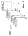
- Figure 2 illustrates the integrated collection of lookup tables of the present invention for the embodiment illustrated in Figure 1, and accessing these lookup tables.
- Figure 3 illustrates an accessed lookup table and accessing its values used to perform static/dynamic companding.
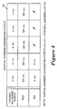
- Figure 4 illustrates how the partial address generator of Figure 1 generates the higher order bits of the composite access address.
- a method and apparatus for selectively performing controllable dynamic companding, and linear/non-linear static companding in a digital video system in an integrated manner is disclosed. Under the disclosed method and apparatus, both dynamic and static companding are advantageously supported. Furthermore, dynamic companding is controllable, and static companding includes linear as well as non-linear static companding.
- dynamic companding is controllable
- static companding includes linear as well as non-linear static companding.
- FIG. 1 a block diagram illustrating one embodiment of the present invention for integrated linear/non-linear static and controllable dynamic companding is shown. Shown is a memory module 16 coupled to a partial address generator 14 . The partial address generator 14 is in turn coupled to a quantization error detector 18 , and a controllable pseudo-random number generator 12 . Together, they cooperate to provide values used to perform static/dynamic companding for digital video data being shifted/modified. Each of these elements 12 - 18 and the manner they cooperate with each other will be described in order with periodic additional references to the remaining figures.
- the memory module 16 will first be described with additional references to Figures 2 - 3 .
- the memory module 16 is used for storing an integrated collection of lookup tables 20 comprising a plurality of lookup tables 24a - 24d having values used to perform linear/non-linear static companding, and at least one set of lookup tables 26a - 26ff having values used to perform dynamic companding.
- the collection of lookup tables 20 comprises four lookup tables 24a - 24d having values used to perform linear/non-linear static companding, and a set of thirty-two lookup tables 26a - 26ff having values used to perform dynamic companding.
- Each of the four lookup tables 24a - 24d having values used to perform linear/non-linear static companding provides eight-bit values to perform static companding for a particular data shifting/modifying function of eight-bit digital video data. In each of the four cases, rounding is performed in a deterministic manner.
- the set of thirty-two lookup tables 26a - 26ff having values used to perform dynamic companding collectively provides eight-bit values to perform dynamic companding for a particular data shifting/modifying function of eight-bit digital video data. In this case, rounding is performed in a stochastic manner.
- the first lookup table 24a having values used to perform static companding may provide values to perform linear static companding for digital video data being shifted/modified from 0 - 255 to 1 - 254 with rounding performed in a deterministic manner;
- the second lookup table 24b may provide a gamma type curve with distributed values to perform non-linear static companding for digital video data being shifted/modified from 0 - 255 to 16 - 235 with rounding also performed in a deterministic manner; etc.
- the set of thirty-two dynamic companding look-up tables 26a - 26ff having values used to perform dynamic companding may provide values to perform dynamic companding for digital video data being shifted/modified from 0 - 255 to 16 - 235 with rounding performed in a stochastic manner.
- the values used to perform static/dynamic companding are accessed using composite addresses of thirteen bits.
- the five higher order bits of a composite address identify a particular lookup table, 24a ,... or 26ff
- the eight low order bits identify a value used to perform static/dynamic companding within the identified lookup table, 24* or 26* .
- the higher order bits are generated by the partial address generator 14 , and the lower order bits are set to equal the digital video data by the processor of the digital video system.
- the higher order bits are generated in such a manner that each of the lookup table within the set of lookup tables having values used to perform dynamic companding has an equal probability of being accessed when values used to perform dynamic companding are accessed.
- the partial address generator 14 and generation of the higher order bits will be described in further detail later.
- the values stored in the set of lookup tables 26a - 26ff to perform dynamic companding for a particular digital video data value reflect the weighted probabilities of rounding the shifted/modified digital video data value in either the up or down direction. These weighted probabilities are determined by the fractional value of the digital video data value being shifted/modified. For example, for the shifted/modified value of an exemplary input value of 10 in the above described example of shifting/modifying digital video data from 0-255 to 16-235, the weighted probability of rounding up is 59% (Fraction(10x219/255)), and the weighted probability of rounding down is 41% (1-Fraction(10x219/255)).
- the number of values rounding a shifted/modified digital video data value up or down are in turn determined by dividing the weighted probabilities with the lookup table access probability (3.125% or 1/32 for the set of 32 lookup tables in this embodiment).
- the lookup table access probability 3.125% or 1/32 for the set of 32 lookup tables in this embodiment.
- the values are randomly dispersed among the lookup tables in the set, so as to be more true to the determined probability.
- One particular approach for achieving these characteristics is to store the values used to perform dynamic companding in the lookup tables, 26a - 26ff , by comparing a value X to a value Y, where X is the fractional value of n/N, and Y is the fractional value of the shifted/modified digital video data, n being a randomly selected integer between 1 and N, where the random selection is made without replacing the selected integers, and N being the number of lookup tables in the set.
- N equals 32
- n is a randomly selected integer between 1 and 32. If X is greater than Y, a shifted/modified digital video data value having been rounded down is substituted.
- a shifted/modified digital video data value having been rounded up is substituted.
- the value stored in the lookup table for the exemplary value of 10 of the above described example is the shifted/modified value having been rounded up, i.e. the value of 25, since X is smaller than Y, Y being equal to 0.59 (Fraction (10 x 219/255)).
- the integer n for the lookup table is 30, the value X is 0.9375 (30/32). Therefore, the value stored in the lookup table for the exemplary value 10 of the above described example is the shifted/modified value having been rounded down, i.e. the value 24, since X is greater than Y.
- the partial address generator 14 generates the higher order bits of the composite addresses for accessing the values of the lookup tables stored in the memory module 16 .
- the partial address generator 14 generates the five higher order bits based on a number of companding scheme selection control signals and a pseudo-random number it received as inputs.
- the partial address generator 14 receives a one-bit dynamic companding scheme selection control signal (dynamic rounding enable (DRE)) from the quantization error detector 18 , a two-bit static companding scheme selection control signal (B ⁇ 0 ⁇ and B ⁇ 1 ⁇ ) from the processor of the digital video system, and a five bit pseudo-random number (PRN ⁇ 0 ⁇ - PRN ⁇ 4 ⁇ ) from the pseudo-random number generator 12 .
- DRE dynamic rounding enable
- B ⁇ 0 ⁇ and B ⁇ 1 ⁇ two-bit static companding scheme selection control signal
- PRN ⁇ 0 ⁇ - PRN ⁇ 4 ⁇ pseudo-random number generator 12
- a ⁇ 9> - A ⁇ 13> equal PRN ⁇ 0> - PRN ⁇ 4> respectively, otherwise, it outputs the padded static companding scheme selection control signal as the higher order bits i.e. A ⁇ 9> - A ⁇ 13> equal B ⁇ 0>, B ⁇ 1>,000 respectively.
- the partial address generator 14 is implemented with a field programmable gate array (FPGA) which is well known in the art and will not be described further. Alternatively, the partial address generator 14 may be implemented with other circuitry providing equivalent functions.
- FPGA field programmable gate array
- the quantisation error detector 18 generates the DRE signal for the partial address generator 14.
- the quantisation error detector 18 generates the DRE signal whenever it detects a potential companding error based on the 8-bit digital video data it received as inputs, thereby controlling and causing dynamic companding to be performed only when it is necessary.
- the quantisation error detector 18 is intended to represent a broad category of quantisation error detectors.
- Such a quantisation error detector generates a DRE signal when various value adjacency conditions, including but not limited to value adjacency in the horizontal and vertical dimensions of pixel adjacency, are detected. Additionally, while the present invention is being described with the dynamic companding scheme selection signal provided by a quantisation error detector, it will be appreciated that the present invention may be practised with the dynamic companding scheme selection signals provided in other manners.
- the controllable pseudo-random number generator 12 generates the pseudo-random number based on the current value of a video control counter, thereby allowing the pseudo-random numbers and in turn the dynamic companding performed to be replicated within a particular area of the video image controlled by the video control counter.
- video control counter include a horizontal pixel counter, a line counter, a frame counter and a field counter.
- the video control counter used is a 5-bit horizontal pixel counter.
- the 5-bit pseudo-random numbers are generated based on the current value of the 5-bit horizontal pixel counter, thereby allowing the pseudo-random numbers and in turn the dynamic companding performed to be replicated within a horizontal line of the video image.
- the controllable pseudo-random number generator 12 is intended to represent a broad category of controllable pseudo-random number generators.
Landscapes
- Engineering & Computer Science (AREA)
- Multimedia (AREA)
- Signal Processing (AREA)
- Physics & Mathematics (AREA)
- Nonlinear Science (AREA)
- Theoretical Computer Science (AREA)
- Image Processing (AREA)
- Compression Or Coding Systems Of Tv Signals (AREA)
Claims (20)
- Digitales Videosystem, welches aus einem Gerät zur wahlweisen Durchführung einer statischen und dynamischen Kompandierung für mehrere digitale Videodaten besteht, wobei mehrere Übertragungsfunktionen zur Verschiebung/Modifizierung der digitalen Videodaten von einem ersten der mehreren Datenbereiche zu einem zweiten entsprechenden der mehreren Datenbereiche verwendet werden, wobei das Gerät aufweist:(a) eine Speichereinrichtung (16) zum Speichern einer integrierten Sammlung von Nachschlagetabellen (24a-24d, 16a-26ff), die Werte haben, die dazu verwendet werden, eine statische und dynamische Kompandierung entsprechend den Übertragungsfunktionen durchzuführen, wobei auf die Werte, die dazu verwendet werden, die statische und dynamische Kompandierung durchzuführen, unter Verwendung von zusammengesetzten Adressen zugegriffen wird, wobei jede der zusammengesetzten Adressen aus mehreren Bits besteht;(b) einen Teiladreßgenerator (14), der mit der Speichereinrichtung (16) gekoppelt ist, um mehrere Auswahlsteuersignale für das statische/dynamische Kompandierungssystem und steuerbare Pseudo-Zufallszahlen als Eingangssignale zu empfangen und mehrere werthöhere Bits für jede der zusammengesetzten Adressen zu erzeugen, wobei die verbleibenden wertniedrigeren Bits für jede der zusammengesetzten Adressen entsprechend gleich den digitalen Videodaten durch einen Prozessor des digitalen Videosystems, der mit der Speichereinrichtung (16) gekoppelt ist, gesetzt werden;(c) eine Auswahlsteuersignalerzeugungseinrichtung für das Kompandierungssystem, die mit dem Teiladreßgenerator (14) gekoppelt ist, um die Auswahlsteuersignale für das Kompandierungssystem zu erzeugen; und(d) einen Pseudo-Zufallszahlgenerator (12), der mit dem Teiladreßgenerator (14) gekoppelt ist, um Werte eines Videosteuerzählers zu empfangen und um die steuerbaren Pseudo-Zufallszahlen zu erzeugen, wobei die erzeugten steuerbaren Pseudo-Zufallszahlen innerhalb eines angegebenen Bereichs des Videobilds, der durch den Videosteuerzähler gesteuert wird, wiederholbar sind.
- Digitales Videosystem nach Anspruch 1, wobei die integrierte Nachschlagetabellensammlung aus vier Nachschlagetabellen (24a-d) besteht, die Werte haben, die dazu verwendet werden, die lineare/nichtlineare statische Kompandierung für eine erste bis vierte Übertragungsfunktion durchzuführen, um die digitalen Videodaten von einem Eingangsdatenbereich zu einem ersten bis vierten entsprechenden Datenbereich zu verschieben/modifizieren, und aus einem Satz von zweiunddreißig Nachschlagetabellen (26a-26ff), die Werte haben, die dazu verwendet werden, die dynamische Kompandierung für eine fünfte Übertragungsfunktion durchzuführen, um die digitalen Videodaten vom Eingangsdatenbereich zu einem fünften Datenbereich zu verschieben/zu modifizieren;jede der digitalen Videodaten und Werte, die dazu verwendet werden, die statische und dynamische Kompandierung durchzuführen, eine Größe von 8-Bits besitzen;jede der zusammengesetzten Adressen eine Größe von 13 Bits besitzen, wobei die fünf werthöheren Bits durch den Teiladreßgenerator (14) erzeugt werden und die acht wertniedrigeren Bits durch den Prozessor des digitalen Videosystems so gesetzt werden, daß sie gleich den digitalen Videodaten sind.
- Digitales Videosystem nach Anspruch 1, wobeijede der zusammengesetzten Adressen eine Größe von 13 Bits besitzt, wobei die fünf werthöheren Bits durch den Teiladreßgenerator (14) erzeugt werden, und die acht wertniedrigeren Bits durch den Prozessor des digitalen Videosystems so gesetzt werden, daß sie gleich den digitalen Videodaten sind;jedes der Auswahlsteuersignale für das dynamische Kompandierungssystem eine Größe von einem Bit besitzt; undjede der steuerbaren Pseudo-Zufallszahlen eine Größe von fünf Bits besitzt.
- Digitales Videosystem nach Anspruch 1, 2 oder 3, wobei der Teiladreßgenerator (14) aus einer teilbild-programmierbaren Gate-Matrix besteht, die mit der Auswahlsteuersignalerzeugungseinrichtung für das Kompandierungssystem, mit dem Pseudo-Zufallszahlgenerator (12) und der Speichereinrichtung (16) gekoppelt ist, um die Auswahlsteuersignale für das statische/dynamische Kompandierungssystem von der Auswahlsteuersignalerzeugungseinrichtung für das Kompandierungssystem und die Pseudo-Zufallszahlen von dem Pseudo-Zufallszahlgenerator (12) als Eingangssignale zu empfangen, und um die fünf werthöheren Bits jeder der zusammengesetzten Adressen für die Speichereinrichtung (16) zu erzeugen.
- Digitales Videosystem nach Anspruch 1, 2, 3 oder 4, wobei die Auswahlsteuersignalerzeugungseinrichtung für das Kompandierungssystem aus einer Quantisierungsfehlerermittlungseinrichtung (18) besteht, die mit dem Teiladreßgenerator (14) gekoppelt ist, um die digitalen Videodaten zu empfangen und bedingungsweise die Auswahlsteuersignale für das dynamische Kompandierungssystem der mehreren Auswahlsteuersignale für das statische/dynamische Kompandierungssystem für den Teiladreßgenerator (14) zu erzeugen, wobei die Quantisierungsfehlerermittlungseinrichtung (18) eines der Auswahlsteuersignale für die dynamische Kompandierung erzeugt, wenn sie einen Potential-Quantisierungsfehler auf der Basis der empfangenen digitalen Videodaten ermittelt.
- Digitales Videosystem nach Anspruch 5, wobei die Quantisierungsfehlerermittlungseinrichtung (18) eines der Auswahlsteuersignale für das dynamische Kompandierungssystem erzeugt, wenn sie einen benachbarten Wertzustand in zumindest einer horizontalen oder einer vertikalen Abmessung einer Pixelnachbarschaft auf der Basis der empfangenen digitalen Videodaten ermittelt.
- Digitales Videosystem nach Anspruch 5 oder 6, wobei ein jedes der Auswahlsteuersignale des dynamischen Kompandierungssystems ein Freigabesignal von einem Bit ist.
- Digitales Videosystem nach Anspruch 5, 6 oder 7, wobei die Auswahlsteuersignalerzeugungseinrichtung für das Kompandierungssystem aus dem Prozessor des digitalen Videosystems besteht, der mit dem Teiladreßgenerator (14) gekoppelt ist, um die Auswahlsteuersignale für das statische Kompandierungssystem der mehreren Auswahlsteuersignale für das statische/dynamische Kompandierungssystem für den Teiladreßgenerator (14) zu erzeugen.
- Digitales Videosystem nach einem der Ansprüche 1 bis 8, wobei ein jedes der Auswahlsteuersignale des statischen Kompandierungssystems ein Zwei-Bit-Signal ist.
- Digitales Videosystem nach einem der vorhergehenden Ansprüche, wobei der Videosteuerzähler, der Werte zum Pseudo-Zufallszahlgenrator (12) liefert, ein Fünf-Bit-Horizontal-Pixelzähler ist, der Horizontal-Pixelzählwerte einer horizontalen Zeile eines Videobildes zum Pseudo-Zufallszahlgenerator (12) bereitstellt.
- Digitales Videosystem nach einem der Ansprüche 1 bis 10, welches außerdem aufweist:einen Prozessor zur Verarbeitung von mehreren digitalen Videodaten;einen digitalen Videosteuerzähler, der mit dem Prozessor gekoppelt ist, um einen Bereich eines Videobilds zu steuern, wobei die Speichereinrichtung (16) und das Auswahlsteuersignalgerät für das Kompandierungssystem mit dem Prozessor und der Pseudo-Zufallszahlgenerator (12) mit dem Videosteuerzähler gekoppelt ist.
- Verfahren zur wahlweisen Durchführung der statischen und dynamischen Kompandierung bei mehreren digitalen Videodaten durch Verwendung mehrerer Übertragungsfunktionen zum Verschieben/Modifizieren der digitalen Videodaten von mehreren ersten Datenbereichen zu mehreren zweiten entsprechenden Datenbereichen, wobei das Verfahren folgende Schritte aufweist:(a) Speichern einer einheitlichen Sammlung von Nachschlagetabellen (20), die mehrere Nachschlagetabellen (24a-24d, 26a-26ff) besitzen, die Werte haben, die dazu verwendet werden, eine statische und dynamische Kompandierung entsprechend den Übertragungsfunktionen durchzuführen, wobei auf die Werte, die verwendet werden, um die statische und dynamische Kompandierung durchzuführen, durch Verwendung von zusammengesetzten Adressen zugegriffen wird, wobei jede der zusammengesetzten Adressen aus mehreren Bits besteht;(b) wahlweises Erzeugen von Auswahlsteuersignalen für das statische und dynamische Kompandierungssystem;(c) Erzeugen von steuerbaren Pseudo-Zufallszahlen auf der Basis der Werte eines Videosteuerzählers, wobei die erzeugten steuerbaren Pseudo-Zufallszahlen innerhalb eines bestimmten Bereichs eines Videobilds wiederholbar sind, der durch den Videosteuerzähler gesteuert wird;(d) Erzeugen von werthöheren Bits für eine jede der zusammengesetzten Adressen auf der Basis der Auswahlsteuersignale für das Kompandierungssystem und der erzeugten steuerbaren Pseudo-Zufallszahlen;(e) Setzen der wertniedrigeren Bits einer jeden der zusammengesetzten Adressen entsprechend so, daß sie gleich den digitalen Videodaten sind; und(f) Zugreifen auf die Werte, die verwendet werden, um die statische und dynamische Kompandierung durchzuführen, wobei die zusammengesetzten Adressen verwendet werden.
- Verfahren nach Anspruch 12, wobeidie integrierte Sammlung der Nachschlagetabellen (20) aus vier Nachschlagetabellen (24a-d) besteht, die Werte haben, die dazu verwendet werden, eine lineare/nichtlineare statische Kompandierung für eine erste bis vierte Übertragungsfunktion durchzuführen, um die digitalen Videodaten von einem Eingangsdatenbereich zu einem ersten bis vierten entsprechenden Datenbereich zu verschieben/zu modifizieren, und aus einem Satz von zweiunddreißig Nachschlagetabellen (26a-ff), die Werte haben, die verwendet werden, die dynamische Kompandierung für eine fünfte Übertragungsfunktion durchzuführen, um die digitalen Videodaten von dem genannten Datenbereich zu einem fünften Datenbereich zu verschieben/zu modifizieren;jede der digitalen Videodaten und der Werte, die verwendet werden, um die statische und dynamische Kompandierung durchzuführen, eine Größe von acht Bits besitzt;jede der zusammengesetzten Adressen eine Größe von dreizehn Bits besitzt, wobei die fünf werthöheren Bits auf der Basis der Auswahlsteuersignale für die statische/dynamische Kompandierung und der Pseudo-Zufallszahlen erzeugt werden, und die acht wertniedrigeren Bits so gesetzt werden, daß sie gleich den digitalen Videodaten sind.
- Verfahren nach Anspruch 12, wobeieine jede der zusammengesetzten Adressen eine Größe von dreizehn Bits besitzt, wobei die fünf werthöheren Bits auf der Basis der Auswahlsteuersignale für die statische/dynamische Kompandierung und der Pseudo-Zufallszahlen erzeugt werden, und die acht wertniedrigeren Bits so gesetzt werden, daß sie gleich den digitalen Videodaten sind;ein jedes der Auswahlsteuersignale für die dynamische Kompandierung eine Größe von einem Bit besitzt; undeine jede der steuerbaren Pseudo-Zufallszahlen eine Größe von fünf Bits besitzt.
- Verfahren nach Anspruch 12, 13 oder 14, wobei der Schritt (d) die Schritte zum Empfang von Ein-Bit-Auswahlsteuersignalen für das dynamische Kompandierungssystem, von Zwei-Bit-Auswahlsteuersignalen für das statische Kompandierungssystem und von Fünf-Bit-Pseudo-Zufallszahlen als Eingangssignale, und die Erzeugung der fünf werthöheren Bits einer jeden der zusammengesetzten Adressen umfaßt.
- Verfahren nach Anspruch 12, 13, 14 oder 15, wobei der Schritt (b) die Schritte zum Empfang der digitalen Videodaten und bedingungsweise die Erzeugung der Auswahlsteuersignale für das dynamische Kompandierungssystem der mehreren Auswahlsteuersignale des statischen/dynamischen Kompandierungssystems umfaßt, wobei ein jedes der Auswahlsteuersignale für das dynamische Kompandierungssystem erzeugt wird, wenn ein Potential-Quantisierungsfehler auf der Basis der empfangenen digitalen Videodaten ermittelt wird.
- Verfahren nach Anspruch 16, wobei ein jedes der Auswahlsteuersignale für das dynamische Kompandierungssystem erzeugt wird, wenn ein benachbarter Wertzustand in zumindest einer horizontalen oder einer vertikalen Abmessung von benachbarten Pixeln auf der Basis der empfangenen digitalen Videodaten ermittelt wird.
- Verfahren nach Anspruch 16, wobei ein jedes der Auswahlsteuersignale für das dynamische Kompandierungssystem, die im Schritt (b) erzeugt werden, ein Ein-Bit-Freigabesignal ist.
- Verfahren nach einem der Ansprüche 12 bis 18, wobei ein jedes der Auswahlsteuersignale für das statische Kompandierungssystem, die im Schritt (b) erzeugt werden, ein Zwei-Bit-Signal ist.
- Verfahren nach einem der Ansprüche 12 bis 19, wobei der Videosteuerzähler, unter welchem die Pseudo-Zufallszahlen im Schritt (c) erzeugt werden, ein Fünf-Bit-Horizontal-Pixelzähler ist, wobei bei dessen horizontalen Pixelzählwerten einer horizontalen Zeile eines Videobildes die Pseudo-Zufallszahlen im Schritt (c) erzeugt werden.
Applications Claiming Priority (2)
| Application Number | Priority Date | Filing Date | Title |
|---|---|---|---|
| US08/004,507 US5357278A (en) | 1993-01-14 | 1993-01-14 | Integrated linear/non-linear static and controllable dynamic companding |
| US4507 | 1993-01-14 |
Publications (3)
| Publication Number | Publication Date |
|---|---|
| EP0606701A2 EP0606701A2 (de) | 1994-07-20 |
| EP0606701A3 EP0606701A3 (de) | 1994-10-26 |
| EP0606701B1 true EP0606701B1 (de) | 1997-01-02 |
Family
ID=21711122
Family Applications (1)
| Application Number | Title | Priority Date | Filing Date |
|---|---|---|---|
| EP93307175A Expired - Lifetime EP0606701B1 (de) | 1993-01-14 | 1993-09-10 | Statische und dynamische integrierte Kompandierung |
Country Status (4)
| Country | Link |
|---|---|
| US (1) | US5357278A (de) |
| EP (1) | EP0606701B1 (de) |
| JP (1) | JPH0723380A (de) |
| DE (1) | DE69307119T2 (de) |
Families Citing this family (4)
| Publication number | Priority date | Publication date | Assignee | Title |
|---|---|---|---|---|
| US7139397B2 (en) * | 2001-07-20 | 2006-11-21 | Stmicroelectronics S.R.L. | Hybrid architecture for realizing a random numbers generator |
| KR100393070B1 (ko) * | 2001-08-08 | 2003-07-31 | 삼성전자주식회사 | 일정 패턴 제거 기능을 갖는 영상 재생 장치 및 그의 영상재생 방법 |
| US6865660B2 (en) * | 2002-06-28 | 2005-03-08 | Micron Technology, Inc. | Method and apparatus for generating deterministic, non-repeating, pseudo-random addresses |
| KR101898643B1 (ko) | 2014-02-25 | 2018-09-14 | 애플 인크. | 비디오 인코딩 및 디코딩을 위한 적응형 전달 함수 |
Family Cites Families (19)
| Publication number | Priority date | Publication date | Assignee | Title |
|---|---|---|---|---|
| GB1218015A (en) * | 1967-03-13 | 1971-01-06 | Nat Res Dev | Improvements in or relating to systems for transmitting television signals |
| NO142768C (no) * | 1974-01-26 | 1980-10-08 | Licentia Gmbh | Kopling for automatisk dynamikk-kompresjon eller -ekspansjon |
| EP0073309B1 (de) * | 1978-12-08 | 1985-07-31 | Etablissement Public de Diffusion dit "Télédiffusion de France" | Kompression und Expansion (Quantizierung) von digitalen differenzcodierten Fernsehsignalen |
| US4208740A (en) * | 1978-12-20 | 1980-06-17 | International Business Machines Corporation | Adaptive delta modulation system |
| US4511922A (en) * | 1982-10-21 | 1985-04-16 | Rca Corporation | Digital television system with truncation error correction |
| US4654695A (en) * | 1985-03-25 | 1987-03-31 | Rca Corporation | Apparatus for reducing the resolution of video samples by truncating the most significant bits |
| DE3571731D1 (en) * | 1985-04-03 | 1989-08-24 | Itt Ind Gmbh Deutsche | Circuit for compressing data for digital video signals with a difference pulse code modulator |
| JPS6247786A (ja) * | 1985-08-27 | 1987-03-02 | Hamamatsu Photonics Kk | 近傍画像処理専用メモリ |
| US4758893A (en) * | 1985-09-23 | 1988-07-19 | Quanticon Inc. | Cinematic dithering for television systems |
| JPS6365719A (ja) * | 1986-09-05 | 1988-03-24 | Nec Corp | 映像信号処理装置 |
| EP0270259B1 (de) * | 1986-12-04 | 1995-02-01 | Quantel Limited | Videosignalverarbeitungssysteme |
| GB2203012B (en) * | 1987-03-30 | 1991-02-20 | Sony Corp | Differential pulse code modulation |
| JP2722485B2 (ja) * | 1988-03-09 | 1998-03-04 | キヤノン株式会社 | ディジタル情報伝送システム |
| GB8813487D0 (en) * | 1988-06-08 | 1988-07-13 | Crosfield Electronics Ltd | Improvements relating to image processing |
| JP2775857B2 (ja) * | 1989-06-20 | 1998-07-16 | ソニー株式会社 | デジタル信号の帯域圧縮回路 |
| US5005082A (en) * | 1989-10-03 | 1991-04-02 | General Electric Company | Video signal compander adaptively responsive to predictions of the video signal processed |
| US4965668A (en) * | 1989-11-09 | 1990-10-23 | The Grass Valley Group, Inc. | Adaptive rounder for video signals |
| US5258928A (en) * | 1990-05-03 | 1993-11-02 | Rca Thomson Licensing Corporation | Parts efficient memory based functional circuit having selectable transfer characteristics |
| US5293165A (en) * | 1990-11-09 | 1994-03-08 | Fujitsu Limited | 5B6B coding rule inverse conversion circuit for digital transmission |
-
1993
- 1993-01-14 US US08/004,507 patent/US5357278A/en not_active Expired - Lifetime
- 1993-09-10 EP EP93307175A patent/EP0606701B1/de not_active Expired - Lifetime
- 1993-09-10 DE DE69307119T patent/DE69307119T2/de not_active Expired - Lifetime
-
1994
- 1994-01-14 JP JP6002760A patent/JPH0723380A/ja active Pending
Also Published As
| Publication number | Publication date |
|---|---|
| EP0606701A3 (de) | 1994-10-26 |
| DE69307119T2 (de) | 1997-04-17 |
| US5357278A (en) | 1994-10-18 |
| JPH0723380A (ja) | 1995-01-24 |
| DE69307119D1 (de) | 1997-02-13 |
| EP0606701A2 (de) | 1994-07-20 |
Similar Documents
| Publication | Publication Date | Title |
|---|---|---|
| EP0199469B1 (de) | Verfahren zur Wertbestimmung an einer halb-tonen Schwellenmatrix | |
| CA1067225A (en) | Animated dithered display systems | |
| EP2166744B1 (de) | System zur Erzeugung binärer Masken und Druckertreiber und Druckverfahren die diese Masken verwenden | |
| US5539843A (en) | Image processing system | |
| US4591842A (en) | Apparatus for controlling the background and foreground colors displayed by raster graphic system | |
| US5329618A (en) | Look-up table for a bridge in a data communications system | |
| EP0272763B1 (de) | Bildanzeigegerät | |
| US4467346A (en) | Adaptive quantizer | |
| US4454506A (en) | Method and circuitry for reducing flicker in symbol displays | |
| US6091511A (en) | Images with spatially varying spatial and gray level resolution | |
| US5745186A (en) | Video signal processing circuit for reducing a video signal | |
| US4475127A (en) | System for transmitting a video signal with short runs avoided in a signal encoded from the video signal | |
| US4532651A (en) | Data filter and compression apparatus and method | |
| US5357278A (en) | Integrated linear/non-linear static and controllable dynamic companding | |
| CA2040562C (en) | Half tone image processing circuit | |
| US5335019A (en) | Digital video data quantization error detection as applied to intelligent dynamic companding | |
| US5696612A (en) | Multiple density level stochastic screening system and method | |
| US5065149A (en) | Scanned document image resolution enhancement | |
| US4389672A (en) | Display of pseudo-gray scale picture signals on multilevel displays | |
| US4870479A (en) | Video graphics memory storage reduction technique | |
| US8743211B2 (en) | Efficient test generator for video test patterns | |
| US3975584A (en) | Dither threshold generators | |
| CA1055627A (en) | Animated dithered display system | |
| US5289279A (en) | Video signal data recoding method for standard memory components and apparatus for perfomring the method | |
| GB2083325A (en) | Display system |
Legal Events
| Date | Code | Title | Description |
|---|---|---|---|
| PUAI | Public reference made under article 153(3) epc to a published international application that has entered the european phase |
Free format text: ORIGINAL CODE: 0009012 |
|
| AK | Designated contracting states |
Kind code of ref document: A2 Designated state(s): DE FR GB |
|
| PUAL | Search report despatched |
Free format text: ORIGINAL CODE: 0009013 |
|
| AK | Designated contracting states |
Kind code of ref document: A3 Designated state(s): DE FR GB |
|
| 17P | Request for examination filed |
Effective date: 19950405 |
|
| GRAG | Despatch of communication of intention to grant |
Free format text: ORIGINAL CODE: EPIDOS AGRA |
|
| 17Q | First examination report despatched |
Effective date: 19960219 |
|
| GRAH | Despatch of communication of intention to grant a patent |
Free format text: ORIGINAL CODE: EPIDOS IGRA |
|
| GRAH | Despatch of communication of intention to grant a patent |
Free format text: ORIGINAL CODE: EPIDOS IGRA |
|
| GRAA | (expected) grant |
Free format text: ORIGINAL CODE: 0009210 |
|
| AK | Designated contracting states |
Kind code of ref document: B1 Designated state(s): DE FR GB |
|
| REF | Corresponds to: |
Ref document number: 69307119 Country of ref document: DE Date of ref document: 19970213 |
|
| ET | Fr: translation filed | ||
| PLBE | No opposition filed within time limit |
Free format text: ORIGINAL CODE: 0009261 |
|
| STAA | Information on the status of an ep patent application or granted ep patent |
Free format text: STATUS: NO OPPOSITION FILED WITHIN TIME LIMIT |
|
| 26N | No opposition filed | ||
| REG | Reference to a national code |
Ref country code: GB Ref legal event code: IF02 |
|
| PGFP | Annual fee paid to national office [announced via postgrant information from national office to epo] |
Ref country code: GB Payment date: 20090909 Year of fee payment: 17 |
|
| PGFP | Annual fee paid to national office [announced via postgrant information from national office to epo] |
Ref country code: DE Payment date: 20090903 Year of fee payment: 17 |
|
| PGFP | Annual fee paid to national office [announced via postgrant information from national office to epo] |
Ref country code: FR Payment date: 20091012 Year of fee payment: 17 |
|
| GBPC | Gb: european patent ceased through non-payment of renewal fee |
Effective date: 20100910 |
|
| REG | Reference to a national code |
Ref country code: FR Ref legal event code: ST Effective date: 20110531 |
|
| REG | Reference to a national code |
Ref country code: DE Ref legal event code: R119 Ref document number: 69307119 Country of ref document: DE Effective date: 20110401 |
|
| PG25 | Lapsed in a contracting state [announced via postgrant information from national office to epo] |
Ref country code: FR Free format text: LAPSE BECAUSE OF NON-PAYMENT OF DUE FEES Effective date: 20100930 Ref country code: DE Free format text: LAPSE BECAUSE OF NON-PAYMENT OF DUE FEES Effective date: 20110401 |
|
| PG25 | Lapsed in a contracting state [announced via postgrant information from national office to epo] |
Ref country code: GB Free format text: LAPSE BECAUSE OF NON-PAYMENT OF DUE FEES Effective date: 20100910 |