EP0606876B1 - Halterung für ein Kennzeichenschild eines Fahrzeugs - Google Patents
Halterung für ein Kennzeichenschild eines Fahrzeugs Download PDFInfo
- Publication number
- EP0606876B1 EP0606876B1 EP94100267A EP94100267A EP0606876B1 EP 0606876 B1 EP0606876 B1 EP 0606876B1 EP 94100267 A EP94100267 A EP 94100267A EP 94100267 A EP94100267 A EP 94100267A EP 0606876 B1 EP0606876 B1 EP 0606876B1
- Authority
- EP
- European Patent Office
- Prior art keywords
- clamping element
- plate
- cylindrical body
- frame
- holder
- Prior art date
- Legal status (The legal status is an assumption and is not a legal conclusion. Google has not performed a legal analysis and makes no representation as to the accuracy of the status listed.)
- Expired - Lifetime
Links
- 238000006073 displacement reaction Methods 0.000 claims 1
- 238000004519 manufacturing process Methods 0.000 description 3
- 238000009434 installation Methods 0.000 description 1
Images

Classifications
-
- B—PERFORMING OPERATIONS; TRANSPORTING
- B60—VEHICLES IN GENERAL
- B60R—VEHICLES, VEHICLE FITTINGS, OR VEHICLE PARTS, NOT OTHERWISE PROVIDED FOR
- B60R13/00—Elements for body-finishing, identifying, or decorating; Arrangements or adaptations for advertising purposes
- B60R13/10—Registration, licensing, or like devices
- B60R13/105—Licence- or registration plates, provided with mounting means, e.g. frames, holders, retainers, brackets
-
- G—PHYSICS
- G09—EDUCATION; CRYPTOGRAPHY; DISPLAY; ADVERTISING; SEALS
- G09F—DISPLAYING; ADVERTISING; SIGNS; LABELS OR NAME-PLATES; SEALS
- G09F7/00—Signs, name or number plates, letters, numerals, or symbols; Panels or boards
- G09F7/18—Means for attaching signs, plates, panels, or boards to a supporting structure
- G09F2007/1843—Frames or housings to hold signs
-
- G—PHYSICS
- G09—EDUCATION; CRYPTOGRAPHY; DISPLAY; ADVERTISING; SEALS
- G09F—DISPLAYING; ADVERTISING; SIGNS; LABELS OR NAME-PLATES; SEALS
- G09F7/00—Signs, name or number plates, letters, numerals, or symbols; Panels or boards
- G09F7/18—Means for attaching signs, plates, panels, or boards to a supporting structure
- G09F2007/1873—Means for attaching signs, plates, panels, or boards to a supporting structure characterised by the type of sign
- G09F2007/1895—Licence number plates
Definitions
- the invention relates to a holder for a license plate of a vehicle, in particular a motor vehicle, consisting of a plate that can be fixed to the vehicle with a frame roughly modeled on the contour of the plate, and at least one clamping element for fixing the plate, the clamping element being displaceable parallel to the plate is received by a guide groove arranged in the frame, and a thrust member is provided for displacing the clamping element.
- a holder for a license plate in which a horizontally displaceable sliding tab is arranged below the frame for receiving the plate, attached to the support elements are. These have a head that engages the frame and is attached to the sliding tab via an undercut neck.
- the sliding tab is provided with recesses assigned to the support elements, through which the support elements engage with their neck. The length of the neck corresponds to the wall ceiling of the cover strip.
- the sliding tab which extends practically over the entire length of the frame, is provided with several support elements, which ensure reliable support of the panel element.
- the recesses are formed from a push-through and a holding window, the push-through window being larger than the head of the supporting element and the holding window being smaller than the head of the supporting element.
- the invention is therefore based on the object of providing a holder for a license plate which is inexpensive to manufacture and which permits simple assembly.
- the thrust member is designed as a cylindrical body which has a radial groove, the groove extending over part of the circumference of the cylindrical body and having an eccentric section for displaceably detecting the clamping element.
- the clamping element is displaceably held parallel to the plate in a guide groove arranged in the frame spar, a pushing element being provided for displacing the clamping element in the direction of the shield.
- the clamping means for fixing the license plate are connected to the holder when the plate is mounted, which considerably simplifies the installation.
- the thrust member is designed as a cylindrical body which is received by a corresponding bore arranged in the frame spar, the cylindrical body having a radial groove which, according to an advantageous embodiment, extends over part of the circumference of the cylindrical body, so that a Eccentric section results through which the clamping element is detected.
- the clamping element itself has a recess for receiving the eccentric section, the size of the recess being smaller than the cross section of the cylindrical body, but larger than the cross section of the eccentric section; the recess preferably has the shape of an oval. That is, when the cylindrical body rotates, and thus when the eccentric section rotates in the recess of the clamping element, the clamping element is displaceable in parallel in the guide groove.
- clamping element can be moved towards the license plate once and away from the license plate with corresponding opposite or further rotation.
- the movement of the clamping element in the direction of the shield is such that it partially overlaps the shield for fixing in one end position.
- a slot adjoins the recess, the width of which corresponds approximately to the cross section of the eccentric section.
- the plate which can be fixed on the vehicle is denoted in each case by 1 and the frame based on the contour of the plate is denoted by a total of 2.
- the horizontally extending upper frame spar 2 a has the groove 2 b for receiving the license plate 3.
- the clamping element held by the guide groove 2f is designated 7 in each case.
- the exact design of the clamping element 7 results from FIGS. 2 to 5; the clamping element 7 is held in the frame member 2c by the thrust member 8.
- the design of the thrust member 8 results from FIGS. 3 and 4, it being clear from FIG. 3 in particular that the thrust member 8 is an essentially cylindrical body which has a radial groove 9.
- the thrust member 8 is guided through the bore 2e in the frame spar 2c.
- the groove 9 is not circumferential, but rather extends only over part of the circumference of the thrust member 8, so that an eccentric section 9a results.
- the groove 9 lies in the recess 7a of the clamping element 7.
- a slot 7b adjoins the recess 7a, which is designed in the manner of an oval.
- the clamping element 7 is now mounted on the frame spar 2c as follows: First, the thrust member 8 is inserted into the bore 2e of the frame spar 2c until the groove 9a is level with the guide groove 2f. Then the thrust member 8 is brought into the position according to FIG. 4, ie the eccentric section 9a is in alignment with the slot 7b. In this position of the push member 8, the clamping element 7 is in the guide groove 2f from above (arrow 11) under light Pushed in pressure until the eccentric section 9a engages in the recess 7a.
Landscapes
- Engineering & Computer Science (AREA)
- Mechanical Engineering (AREA)
- Physics & Mathematics (AREA)
- General Physics & Mathematics (AREA)
- Theoretical Computer Science (AREA)
- Vehicle Waterproofing, Decoration, And Sanitation Devices (AREA)
- Body Structure For Vehicles (AREA)
- Traffic Control Systems (AREA)
- Storage Of Web-Like Or Filamentary Materials (AREA)
- Motor Or Generator Frames (AREA)
Description
- Die Erfindung betrifft eine Halterung für ein Kennzeichenschild eines Fahrzeugs, insbesondere eines Kraftfahrzeugs, bestehend aus einer an dem Fahrzeug fixierbaren Platte mit einem in etwa der Kontur des Schildes nachempfundenen Rahmen, und mindestens einem Klemmelement zur Fixierung des Schildes, wobei das Klemmelement parallel zur Platte verschieblich von einer in dem Rahmen angeordneten Führungsnut aufgenommen wird, und wobei zur Verschiebung des Klemmelements ein Schubglied vorgesehen ist.
- So ist beispielsweise aus dem DE-GM 92 05 976, der eine Halterung nach dem Oberbegriff des Anspruchs 1 beschreibt, eine Halterung für ein Kennzeichenschild bekannt, bei der unterhalb des Rahmens zur Aufnahme des Schildes eine horizontal verschiebliche Schiebelasche angeordnet ist, an der Stützelemente befestigt sind. Diese besitzen einen an dem Rahmen angreifenden Kopf, der über einen hinterschnittenen Hals an der Schiebelasche befestigt ist. Die Schiebelasche ist mit den Stützelementen zugeordneten Ausnehmungen versehen, durch welche die Stützelemente mit ihrem Hals durchgreifen. Dabei entspricht die Länge des Halses der Wanddecke der Deckleiste. Die praktisch über die gesamte Rahmenlänge reichende Schiebelasche ist mit mehreren Stützelementen versehen, die eine zuverlässige Abstützung des Tafelelementes gewährleisten. Die Ausnehmungen sind aus einem Durchsteck- und einem Haltefenster gebildet, wobei das Durchsteckfenster größer ist als der Kopf des Stützelementes und das Haltefenster kleiner ist als der Kopf des Stützelementes. Hierdurch kann die Schiebelasche im Bereich der Durchsteckfenster in den Rahmen gesteckt werden und durch horizontales Verschieben der Köpfe bis in die Haltefenster verriegelt werden, denn die Köpfe hinterschneiden die Haltefenster, so daß ein Entfernen der Schiebelasche nunmehr nicht möglich ist.
- Nachteilig hieran ist, daß das Kennzeichenschild an zumindest zwei Stellen in den Rahmen eingefädelt werden muß. Damit dies gelingt, ist eine präzise Fertigung der einzelnen Teile notwendig, was sehr hohe Produktionskosten zur Folge hat. Darüber hinaus ist auch die Montage sehr aufwendig, da das Einfädeln der Schiebelasche sehr viel Geschick erfordert.
- Der Erfindung liegt daher die Aufgabe zugrunde, eine Halterung für ein Kennzeichenschild zu schaffen, das preiswert in der Herstellung ist und eine einfache Montage zuläßt.
- Erfindungsgemäß wird die Aufgabe dadurch gelöst, daß das Schubglied als zylindrischer Körper ausgebildet ist, der eine radiale Nut aufweist, wobei die Nut sich über einen Teil des Umfangs des zylindrischen Körpers erstreckt und einen exzentrischen Abschnitt zum verschieblichen Erfassen des Klemmelementes aufweist.
- Hierdurch ist das Klemmelement parallel zur Platte verschieblich in einer in dem Rahmenholm angeordneten Führungsnut gehalten, wobei zur Verschiebung des Klemmelementes in Richtung des Schildes ein Schubglied vorgesehen ist. Hierbei sind die Klemmittel zur Fixierung des Kennzeichenschildes bei der Montage des Schildes mit der Halterung verbunden, was die Montage erheblich vereinfacht.
- Im einzelnen ist das Schubglied als zylindrischer Körper ausgebildet, der von einer im Rahmenholm angeordneten entsprechenden Bohrung aufgenommen wird, wobei der zylindrische Körper eine radiale Nut aufweist, die sich nach einer vorteilhaften Ausbildung über einen Teil des Umfangs des zylindrischen Körpers erstreckt, so daß sich ein exzentrischer Abschnitt ergibt, durch den das Klemmelement erfaßt wird.
- Das Klemmelement selbst besitzt eine Aussparung zur Aufnahme des exzentrischen Abschnittes, wobei die Größe der Aussparung kleiner als der Querschnitt des zylindrischen Körpers, aber größer als der Querschnitt des exzentrischen Abschnitts ist; vorzugsweise weist die Aussparung die Form eines Ovals auf. D.h., daß bei Drehung des zylindrischen Körpers, und somit bei Drehung des exzentrischen Abschnitts in der Aussparung des Klemmelements das Klemmelement in der Führungsnut parallel verschiebbar ist.
- Hierdurch wird erreicht, daß das Klemmelement einmal auf das Kennzeichenschild zu und bei entsprechend gegenläufiger bzw. weiterer Drehung von dem Kennzeichenschild wegbewegt werden kann. Die Bewegung des Klemmelements in Richtung des Schildes ist derart, daß es das Schild zur Fixierung in der einen Endlage partiell überlappt.
- Um die Montage zu ermöglichen, schließt sich an die Aussparung ein Schlitz an, dessen Breite in etwa dem Querschnitt des exzentrischen Abschnitts entspricht. Durch diesen Schlitz wird das Klemmelement in die Führungsnut eingeschoben, wobei hierbei der exzentrische Abschnitt mit seiner Schmalseite parallel zum Schlitz liegt.
- Anhand der nachstehenden Zeichnungen ist die Ausführungsform beispielhaft näher erläutert.
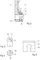
- Fig. 1
- zeigt eine Ausführungsform einer
Halterung für Kennzeichenschilder in einer
Draufsicht, wobei die Klemmelemente
verschiebbar im Rahmenholm angeordnet sind; - Fig. 2
- zeigt einen Schnitt gemäß der Linie VI-VI aus Fig. 1;
- Fig. 3
- zeigt das Schubglied in einer Seitenansicht;
- Fig. 4
- zeigt eine Draufsicht auf das Schubglied;
- Fig. 5
- zeigt das Klemmelement in einer Draufsicht.
- Bei der Ausführungsform einer Halterung für ein Kennzeichenschild gemäß der Fig. 1 bis 5 ist die am Fahrzeug fixierbare Platte jeweils mit 1 und der der Kontur des Schildes nachempfundene Rahmen insgesamt mit 2 bezeichnet. Der horizontal verlaufende obere Rahmenholm 2a besitzt die Nut 2b zur Aufnahme des Kennzeichenschildes 3.
- Bei der gemäß den Fig. 1 bis 5 dargestellten Ausführungsform ist das durch die Führungsnut 2f gehaltene Klemmelement jeweils mit 7 bezeichnet. Die genaue Ausgestaltung des Klemmelementes 7 ergibt sich aus den Fig. 2 bis 5; das Klemmelement 7 ist hierbei durch das Schubglied 8 in dem Rahmenholm 2c gehalten. Die Ausbildung des Schubgliedes 8 ergibt sich aus den Fig. 3 und 4 , wobei insbesondere aus Fig. 3 erkennbar ist, daß das Schubglied 8 ein im wesentlichen zylindrischer Körper ist, der eine radiale Nut 9 aufweist. Geführt ist das Schubglied 8 durch die Bohrung 2e im Rahmenholm 2c. Die Nut 9 ist jedoch nicht umlaufend ausgebildet, sondern erstreckt sich vielmehr nur über einen Teil des Umfangs des Schubgliedes 8, so daß sich ein exzentrischer Abschnitt 9a ergibt. Zur Drehung des Schubgliedes 8 befindet sich auf der Oberseite eine Nut 10 zum Ansatz eines Schraubendrehers. Im eingebauten Zustand des Klemmelementes 7 (Fig. 2), liegt die Nut 9 in der Aussparung 7a des Klemmelementes 7. An die nach Art eines Ovals ausgebildete Aussparung 7a schließt sich ein Schlitz 7b an. Die Montage des Klemmelementes 7 an dem Rahmenholm 2c erfolgt nun wie folgt:
Zunächst wird das Schubglied 8 in die Bohrung 2e des Rahmenholmes 2c eingeführt, bis die Nut 9a auf gleicher Höhe mit der Führungsnut 2f liegt. Alsdann wird das Schubglied 8 in die Stellung gemäß Fig. 4 gebracht, d. h., daß sich der exzentrische Abschnitt 9a fluchtend zum Schlitz 7b befindet. In dieser Stellung des Schubgliedes 8 wird das Klemmelement 7 in die Führungsnut 2f von oben (Pfeil 11) unter leichtem Druck eingeschoben, bis der exzentrische Abschnitt 9a in die Aussparung 7a einrastet. Bei Drehung des Schubgliedes 8 in die Stellung gemäß Fig. 2, erfolgt eine Verschiebung des Klemmelementes 7 entgegen der Richtung des Pfeiles 11,
wobei in der Endstellung des Klemmelementes 7 das Schild 3 von dem Klemmelement überlappt wird (Fig. 2). Bei entgegengesetzter Drehung des Schubgliedes 8 wird das Klemmelement 7 wieder in Richtung des Pfeiles 11 aus dem Bereich des Kennzeichenschildes 3 verschoben. In dieser Endstellung (nicht dargestellt) kann das Kennzeichenschild herausgenommen werden.
Claims (5)
- Halterung für ein Kennzeichenschild eines Fahrzeugs, insbesondere eines Kraftfahrzeugs, bestehend aus einer an dem Fahrzeug fixierbaren Platte (1) mit einem in etwa der Kontur des Schildes (3) nachempfundenen Rahmen, und mindestens ein Klemmelement (7) zur Fixierung des Schildes (3), wobei das Klemmelement (7) parallel zur Platte (1) verschieblich von einer in dem Rahmen angeordneten Führungsnut (2f) aufgenommen wird, und wobei zur Verschiebung des Klemmelements (7) ein Schubglied (8) vorgesehen ist,
dadurch gekennzeichnet, daß das Schubglied (8) als zylindrischer Körper ausgebildet ist, der eine radiale Nut (9) aufweist, wobei die Nut (9) sich über einen Teil des Umfangs des zylindrischen Körpers (8) erstreckt, und einen exzentrischer Abschnitt (9a) zum verschieblichen Erfassen des Klemmelementes (7) aufweist. - Halterung nach Anspruch 1,
dadurch gekennzeichnet, daß das Klemmelement (7) eine Aussparung (7a) zur Aufnahme des exzentrischen Abschnitts (9a) aufweist, wobei die Größe der Aussparung (7a) kleiner als der Querschnitt des zylindrischen Körpers (8), aber großer als der Querschnitt des exzentrischen Abschnitts (9a) ist. - Halterung nach Anspruch 1,
dadurch gekennzeichnet, daß der zylindrische Körper (8) Mittel (10) zum Ansatz eines Werkzeugs aufweist. - Halterung nach Anspruch 1,
dadurch gekennzeichnet, daß zur Aufnahme des zylindrischen Körpers (8) der Rahmenholm (2c) eine entsprechende Bohrung (2e) aufweist. - Halterung nach Anspruch 2,
dadurch gekennzeichnet, daß sich die Aussparung (7a) an einen Schlitz (7b) anschließt, dessen Breite in etwa dem Querschnitt des exzentrischen Abschnitts (9a) entspricht.
Applications Claiming Priority (2)
| Application Number | Priority Date | Filing Date | Title |
|---|---|---|---|
| DE9300229U | 1993-01-11 | ||
| DE9300229U DE9300229U1 (de) | 1993-01-11 | 1993-01-11 | Halterung für ein Kennzeichenschild eines Fahrzeugs |
Publications (2)
| Publication Number | Publication Date |
|---|---|
| EP0606876A1 EP0606876A1 (de) | 1994-07-20 |
| EP0606876B1 true EP0606876B1 (de) | 1996-09-11 |
Family
ID=6887976
Family Applications (1)
| Application Number | Title | Priority Date | Filing Date |
|---|---|---|---|
| EP94100267A Expired - Lifetime EP0606876B1 (de) | 1993-01-11 | 1994-01-10 | Halterung für ein Kennzeichenschild eines Fahrzeugs |
Country Status (4)
| Country | Link |
|---|---|
| EP (1) | EP0606876B1 (de) |
| AT (1) | ATE142572T1 (de) |
| DE (2) | DE9300229U1 (de) |
| ES (1) | ES2092339T3 (de) |
Families Citing this family (4)
| Publication number | Priority date | Publication date | Assignee | Title |
|---|---|---|---|---|
| DE9400768U1 (de) * | 1994-01-18 | 1994-05-05 | AHB - Autohandel-Bedarf GmbH, 40789 Monheim | Kennzeichenverstärker |
| DE19637867C2 (de) * | 1996-09-17 | 1998-07-16 | Utsch Kg Erich | Befestigungsvorrichtung für Kennzeichenschilder von Kraftfahrzeugen |
| DE202013004468U1 (de) * | 2013-05-14 | 2014-08-19 | Dominic Meyer | Haltevorrichtung für ein Kennzeichenschild an Fahrzeugen |
| DE102021003003A1 (de) | 2021-06-14 | 2022-12-15 | Walz GmbH & Co.KG | Vorrichtung zur Aufnahme eines Tafelelements |
Family Cites Families (8)
| Publication number | Priority date | Publication date | Assignee | Title |
|---|---|---|---|---|
| DE8223840U1 (de) * | 1982-12-02 | Walter Bender Ohg, 5905 Freudenberg | Warntafel für den Transport gefährlicher Güter | |
| CH658833A5 (en) * | 1984-08-09 | 1986-12-15 | Edeltraud Fallwick | Support for a vehicle number plate |
| DE8600110U1 (de) * | 1986-01-04 | 1986-02-27 | Weigel, Hans, 7538 Keltern | Verstärkungsunterlagen aus Kunststoff für KFZ-Kennzeichen |
| DE8634651U1 (de) * | 1986-12-24 | 1987-09-03 | Unger, Bernhard, 7941 Unlingen | Halteplatte für Fahrzeug-Kennzeichnungsschilder |
| DE8716527U1 (de) * | 1987-12-15 | 1988-02-18 | Walz, Thomas, 7901 Lonsee | Vorrichtung zur Aufnahme einer Kennzeichentafel |
| DE8912546U1 (de) * | 1989-10-23 | 1990-07-12 | Weigel, Hans, Felanitx, Mallorca | Verstärkungsunterlage aus Kunststoff für Kennzeichenschilder bei Kraftfahrzeugen |
| DE9205976U1 (de) * | 1991-05-17 | 1992-07-23 | Walz, Thomas, 89160 Dornstadt | Vorrichtung zur Aufnahme eines Tafelelements |
| DE9115553U1 (de) * | 1991-12-16 | 1992-02-20 | Weigel, Hans, 7134 Knittlingen | Autoschilder-Universal-Schnellbefestigung aus Kunststoff für alle Arten von Beschilderungen in Autoschildergröße |
-
1993
- 1993-01-11 DE DE9300229U patent/DE9300229U1/de not_active Expired - Lifetime
-
1994
- 1994-01-10 DE DE59400606T patent/DE59400606D1/de not_active Expired - Lifetime
- 1994-01-10 ES ES94100267T patent/ES2092339T3/es not_active Expired - Lifetime
- 1994-01-10 EP EP94100267A patent/EP0606876B1/de not_active Expired - Lifetime
- 1994-01-10 AT AT94100267T patent/ATE142572T1/de not_active IP Right Cessation
Also Published As
| Publication number | Publication date |
|---|---|
| DE59400606D1 (de) | 1996-10-17 |
| ATE142572T1 (de) | 1996-09-15 |
| ES2092339T3 (es) | 1996-11-16 |
| DE9300229U1 (de) | 1993-03-25 |
| EP0606876A1 (de) | 1994-07-20 |
Similar Documents
| Publication | Publication Date | Title |
|---|---|---|
| EP0421058B1 (de) | Halteelement aus Kunststoff | |
| EP0231440B1 (de) | Sonnenblende für Fahrzeuge | |
| EP0628737A1 (de) | Halteelement | |
| DE3626926C2 (de) | ||
| EP0791715A1 (de) | Scharnier-und Feststellereinheit für aushängbare Kraftwagentüren | |
| DE3149518A1 (de) | Sicherheitsgurtsystem fuer kraftfahrzeuge | |
| EP0606876B1 (de) | Halterung für ein Kennzeichenschild eines Fahrzeugs | |
| WO2008125318A2 (de) | Verstellbare stangenführung | |
| EP0872408B1 (de) | Anordnung in einem Cockpitbereich eines Kraftfahrzeuges | |
| EP0513583B1 (de) | Vorrichtung zum verschiebbaren Halten eines Stossfänger-Seitenteils an einer Fahrzeugkarosserie | |
| DE4029694A1 (de) | Griff fuer eine kraftfahrzeugtuer | |
| EP0616108B1 (de) | Lamellenstore | |
| DE4124528C1 (en) | Solid car roof with sun roof aperture - has threaded adjuster with two parts, effective in opposite directions via link | |
| DE69000426T2 (de) | Aeusserer abstreifer fuer kraftfahrzeugfenster. | |
| DE2553263C2 (de) | Befestigungselement zur Halterung von C-förmigen Profilen an Rahmen, Tragschienen o.dgl. | |
| DE29714671U1 (de) | Lochscheibe | |
| EP1216336B1 (de) | Beschlagteil | |
| DE4117014C2 (de) | Scharnier | |
| DE2905607A1 (de) | Jalousie fuer fenster | |
| DE4233402C2 (de) | Befestigungsvorrichtung für Schienen mit Reihen von Durchbrüchen und Bohrungen | |
| DE3242100C2 (de) | ||
| DE3220052C2 (de) | Dachgepäckträger für ein Kraftfahrzeug | |
| DE2248576C3 (de) | Rastbolzen zum Festlegen einer Leiste an einem Fensterrahmen, Türrahmen o.dgl | |
| EP0551873B1 (de) | Kunststoffbefestigungselement zum Aufdrücken auf einen Gewindebolzen | |
| EP0388815B1 (de) | Höhenverstellbarer Umlenkbeschlag für Sicherheitsgurte von Kraftfahrzeugen |
Legal Events
| Date | Code | Title | Description |
|---|---|---|---|
| PUAI | Public reference made under article 153(3) epc to a published international application that has entered the european phase |
Free format text: ORIGINAL CODE: 0009012 |
|
| AK | Designated contracting states |
Kind code of ref document: A1 Designated state(s): AT CH DE ES FR GB IT LI NL PT SE |
|
| 17P | Request for examination filed |
Effective date: 19940620 |
|
| 17Q | First examination report despatched |
Effective date: 19950330 |
|
| GRAG | Despatch of communication of intention to grant |
Free format text: ORIGINAL CODE: EPIDOS AGRA |
|
| GRAH | Despatch of communication of intention to grant a patent |
Free format text: ORIGINAL CODE: EPIDOS IGRA |
|
| RAP3 | Party data changed (applicant data changed or rights of an application transferred) |
Owner name: HEPLA-KUNSTSTOFFTECHNIK GMBH |
|
| GRAH | Despatch of communication of intention to grant a patent |
Free format text: ORIGINAL CODE: EPIDOS IGRA |
|
| GRAA | (expected) grant |
Free format text: ORIGINAL CODE: 0009210 |
|
| AK | Designated contracting states |
Kind code of ref document: B1 Designated state(s): AT CH DE ES FR GB IT LI NL PT SE |
|
| REF | Corresponds to: |
Ref document number: 142572 Country of ref document: AT Date of ref document: 19960915 Kind code of ref document: T |
|
| REG | Reference to a national code |
Ref country code: CH Ref legal event code: NV Representative=s name: R. A. EGLI & CO. PATENTANWAELTE |
|
| REF | Corresponds to: |
Ref document number: 59400606 Country of ref document: DE Date of ref document: 19961017 |
|
| ITF | It: translation for a ep patent filed | ||
| REG | Reference to a national code |
Ref country code: ES Ref legal event code: FG2A Ref document number: 2092339 Country of ref document: ES Kind code of ref document: T3 |
|
| PGFP | Annual fee paid to national office [announced via postgrant information from national office to epo] |
Ref country code: SE Payment date: 19961216 Year of fee payment: 4 |
|
| PGFP | Annual fee paid to national office [announced via postgrant information from national office to epo] |
Ref country code: PT Payment date: 19961220 Year of fee payment: 4 |
|
| SC4A | Pt: translation is available |
Free format text: 960911 AVAILABILITY OF NATIONAL TRANSLATION |
|
| GBT | Gb: translation of ep patent filed (gb section 77(6)(a)/1977) |
Effective date: 19961204 |
|
| ET | Fr: translation filed | ||
| PLBE | No opposition filed within time limit |
Free format text: ORIGINAL CODE: 0009261 |
|
| STAA | Information on the status of an ep patent application or granted ep patent |
Free format text: STATUS: NO OPPOSITION FILED WITHIN TIME LIMIT |
|
| 26N | No opposition filed | ||
| PGFP | Annual fee paid to national office [announced via postgrant information from national office to epo] |
Ref country code: GB Payment date: 19971224 Year of fee payment: 5 |
|
| PGFP | Annual fee paid to national office [announced via postgrant information from national office to epo] |
Ref country code: CH Payment date: 19980108 Year of fee payment: 5 |
|
| PG25 | Lapsed in a contracting state [announced via postgrant information from national office to epo] |
Ref country code: SE Free format text: LAPSE BECAUSE OF NON-PAYMENT OF DUE FEES Effective date: 19980111 |
|
| PG25 | Lapsed in a contracting state [announced via postgrant information from national office to epo] |
Ref country code: PT Free format text: LAPSE BECAUSE OF NON-PAYMENT OF DUE FEES Effective date: 19980731 |
|
| EUG | Se: european patent has lapsed |
Ref document number: 94100267.7 |
|
| REG | Reference to a national code |
Ref country code: PT Ref legal event code: MM4A Free format text: LAPSE DUE TO NON-PAYMENT OF FEES Effective date: 19980731 |
|
| PG25 | Lapsed in a contracting state [announced via postgrant information from national office to epo] |
Ref country code: GB Free format text: LAPSE BECAUSE OF NON-PAYMENT OF DUE FEES Effective date: 19990110 |
|
| PG25 | Lapsed in a contracting state [announced via postgrant information from national office to epo] |
Ref country code: LI Free format text: LAPSE BECAUSE OF NON-PAYMENT OF DUE FEES Effective date: 19990131 Ref country code: CH Free format text: LAPSE BECAUSE OF NON-PAYMENT OF DUE FEES Effective date: 19990131 |
|
| GBPC | Gb: european patent ceased through non-payment of renewal fee |
Effective date: 19990110 |
|
| REG | Reference to a national code |
Ref country code: CH Ref legal event code: PL |
|
| PGFP | Annual fee paid to national office [announced via postgrant information from national office to epo] |
Ref country code: NL Payment date: 20040123 Year of fee payment: 11 |
|
| PG25 | Lapsed in a contracting state [announced via postgrant information from national office to epo] |
Ref country code: IT Free format text: LAPSE BECAUSE OF NON-PAYMENT OF DUE FEES;WARNING: LAPSES OF ITALIAN PATENTS WITH EFFECTIVE DATE BEFORE 2007 MAY HAVE OCCURRED AT ANY TIME BEFORE 2007. THE CORRECT EFFECTIVE DATE MAY BE DIFFERENT FROM THE ONE RECORDED. Effective date: 20050110 |
|
| PGFP | Annual fee paid to national office [announced via postgrant information from national office to epo] |
Ref country code: AT Payment date: 20050118 Year of fee payment: 12 |
|
| PG25 | Lapsed in a contracting state [announced via postgrant information from national office to epo] |
Ref country code: NL Free format text: LAPSE BECAUSE OF NON-PAYMENT OF DUE FEES Effective date: 20050801 |
|
| NLV4 | Nl: lapsed or anulled due to non-payment of the annual fee |
Effective date: 20050801 |
|
| PG25 | Lapsed in a contracting state [announced via postgrant information from national office to epo] |
Ref country code: AT Free format text: LAPSE BECAUSE OF NON-PAYMENT OF DUE FEES Effective date: 20060110 |
|
| PGFP | Annual fee paid to national office [announced via postgrant information from national office to epo] |
Ref country code: ES Payment date: 20080130 Year of fee payment: 15 |
|
| PGFP | Annual fee paid to national office [announced via postgrant information from national office to epo] |
Ref country code: FR Payment date: 20080111 Year of fee payment: 15 |
|
| REG | Reference to a national code |
Ref country code: FR Ref legal event code: ST Effective date: 20091030 |
|
| REG | Reference to a national code |
Ref country code: ES Ref legal event code: FD2A Effective date: 20090112 |
|
| PG25 | Lapsed in a contracting state [announced via postgrant information from national office to epo] |
Ref country code: FR Free format text: LAPSE BECAUSE OF NON-PAYMENT OF DUE FEES Effective date: 20090202 Ref country code: ES Free format text: LAPSE BECAUSE OF NON-PAYMENT OF DUE FEES Effective date: 20090112 |
|
| PGFP | Annual fee paid to national office [announced via postgrant information from national office to epo] |
Ref country code: DE Payment date: 20091027 Year of fee payment: 17 |
|
| REG | Reference to a national code |
Ref country code: DE Ref legal event code: R119 Ref document number: 59400606 Country of ref document: DE Effective date: 20110802 |
|
| PG25 | Lapsed in a contracting state [announced via postgrant information from national office to epo] |
Ref country code: DE Free format text: LAPSE BECAUSE OF NON-PAYMENT OF DUE FEES Effective date: 20110802 |