EP0606877A2 - Ferrure pour une serrure avec un pêne demi-tour et un pêne dormant - Google Patents
Ferrure pour une serrure avec un pêne demi-tour et un pêne dormant Download PDFInfo
- Publication number
- EP0606877A2 EP0606877A2 EP94100268A EP94100268A EP0606877A2 EP 0606877 A2 EP0606877 A2 EP 0606877A2 EP 94100268 A EP94100268 A EP 94100268A EP 94100268 A EP94100268 A EP 94100268A EP 0606877 A2 EP0606877 A2 EP 0606877A2
- Authority
- EP
- European Patent Office
- Prior art keywords
- latch
- nut
- handle
- bolt
- fitting according
- Prior art date
- Legal status (The legal status is an assumption and is not a legal conclusion. Google has not performed a legal analysis and makes no representation as to the accuracy of the status listed.)
- Granted
Links
- 230000005540 biological transmission Effects 0.000 claims abstract description 43
- 230000007246 mechanism Effects 0.000 claims abstract description 13
- 230000006835 compression Effects 0.000 claims description 6
- 238000007906 compression Methods 0.000 claims description 6
- 239000002023 wood Substances 0.000 description 3
- 241000207836 Olea <angiosperm> Species 0.000 description 2
- 240000007817 Olea europaea Species 0.000 description 1
- 229910000831 Steel Inorganic materials 0.000 description 1
- 230000004308 accommodation Effects 0.000 description 1
- 230000008878 coupling Effects 0.000 description 1
- 238000010168 coupling process Methods 0.000 description 1
- 238000005859 coupling reaction Methods 0.000 description 1
- 238000006073 displacement reaction Methods 0.000 description 1
- 230000000694 effects Effects 0.000 description 1
- 230000002349 favourable effect Effects 0.000 description 1
- 238000001746 injection moulding Methods 0.000 description 1
- 239000002184 metal Substances 0.000 description 1
- 230000002093 peripheral effect Effects 0.000 description 1
- 239000010959 steel Substances 0.000 description 1
Images


Classifications
-
- E—FIXED CONSTRUCTIONS
- E05—LOCKS; KEYS; WINDOW OR DOOR FITTINGS; SAFES
- E05B—LOCKS; ACCESSORIES THEREFOR; HANDCUFFS
- E05B53/00—Operation or control of locks by mechanical transmissions, e.g. from a distance
-
- E—FIXED CONSTRUCTIONS
- E05—LOCKS; KEYS; WINDOW OR DOOR FITTINGS; SAFES
- E05B—LOCKS; ACCESSORIES THEREFOR; HANDCUFFS
- E05B59/00—Locks with latches separate from the lock-bolts or with a plurality of latches or lock-bolts
-
- E—FIXED CONSTRUCTIONS
- E05—LOCKS; KEYS; WINDOW OR DOOR FITTINGS; SAFES
- E05B—LOCKS; ACCESSORIES THEREFOR; HANDCUFFS
- E05B15/00—Other details of locks; Parts for engagement by bolts of fastening devices
- E05B15/0033—Spindles for handles, e.g. square spindles
-
- E—FIXED CONSTRUCTIONS
- E05—LOCKS; KEYS; WINDOW OR DOOR FITTINGS; SAFES
- E05B—LOCKS; ACCESSORIES THEREFOR; HANDCUFFS
- E05B15/00—Other details of locks; Parts for engagement by bolts of fastening devices
- E05B15/02—Striking-plates; Keepers; Bolt staples; Escutcheons
-
- E—FIXED CONSTRUCTIONS
- E05—LOCKS; KEYS; WINDOW OR DOOR FITTINGS; SAFES
- E05B—LOCKS; ACCESSORIES THEREFOR; HANDCUFFS
- E05B63/00—Locks or fastenings with special structural characteristics
- E05B63/0065—Operating modes; Transformable to different operating modes
- E05B63/0069—Override systems, e.g. allowing opening from inside without the key, even when locked from outside
-
- E—FIXED CONSTRUCTIONS
- E05—LOCKS; KEYS; WINDOW OR DOOR FITTINGS; SAFES
- E05B—LOCKS; ACCESSORIES THEREFOR; HANDCUFFS
- E05B63/00—Locks or fastenings with special structural characteristics
- E05B63/16—Locks or fastenings with special structural characteristics with the handles on opposite sides moving independently
Definitions
- the invention relates to a fitting of the type specified in the preamble of claim 1.
- Locks with separate latches and bolts are mainly attached to the doors of bathrooms, toilets, changing rooms or the like.
- the fittings previously known for such locks have a handle on the inside of the door, e.g. a door handle to operate the latch and a second handle, e.g. an olive to open the latch.
- Both handles can be coupled via an actuator that protrudes through a latch or bolt nut of the lock, usually a conventional square mandrel, with a fitting provided on the outside of the door, which also has a handle for the latch, but in the area of the bolt actuator with a free / occupied Display and possibly provided with an emergency opening device.
- the invention is therefore based on the object to remedy this situation and to design the fitting described at the outset in such a way that a simplified latch actuation and a more secure free / busy display are possible.
- the invention has the advantage that, despite the use of conventional locks, it enables latch and bolt actuation with only one handle. It is therefore only necessary to replace the fitting if necessary. This is generally not a problem because the distances between the latch and bolt actuators have been standardized for a long time and therefore only a single fitting size adapted to this distance needs to be provided.
- the transmission ratio within the fitting according to the invention is preferably selected so that the locking position of the bolt results after the handle has been rotated by approximately 30 °.
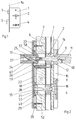
- Fig. 1 shows a well-known lock, which is preferably used on doors of rooms that should be lockable from the inside.
- the lock contains a lock case 1, in which a latch nut 2 for a latch 3 and a latch nut 4 for a latch 5 are rotatably mounted.
- the lock is usually stored in a lock pocket 6 of a door 7 or the like according to FIG. 2 and fastened to the inside edge of the door with a face plate 1a (FIG. 1), while the latch 3 and the bolt 5 can be seen in FIG. 1
- the closed position protrude into recesses which are formed in a frame or the like carrying the door 7 or the like.
- the latch 3 and the bolt 5 can be retracted into a fully recessed position in the lock case 1 by rotating the latch nut 2 or the latch nut 4.
- the rotation is usually carried out by means of a latch actuator 8 or a latch actuator 9, both of which preferably consist of conventional square profiles and protrude through a corresponding cross-section recess in the latch or latch nut 2 or 4, and a pair of handles 10 and 11 which can be coupled on both sides of the door 7 (Fig. 2) with the actuators 8.9.
- the handle 10 is arranged on the inside of the door 7 and the handle 11 on the outside of the door 7.
- Lock structures and fittings of the type described are generally known and therefore do not need to be explained in more detail.
- the fitting for the outside of the door shown schematically in FIG. 2, is designed in a generally known manner and is provided with a lower part 12 in which a neck section 14 of the handle 11 pushed onto the latch actuating element 8 is rotatably mounted and which is covered by a cover cap 15.
- the end of the bolt actuating member 9 located on the outside of the door projects e.g. in a known manner in a viewing plate 16 of a free / busy display, which makes the respective position of the bolt 5 (FIG. 1) or the bolt nut 4 recognizable from the outside and is usually provided with a means for attaching an emergency opening tool.
- a fitting according to the invention is attached to the inside of the door 7.
- the lower part 18 is cap-shaped and provided with a peripheral edge 20 which is supported on the door 7 or the like, so that a cavity 21 is formed.
- an inner part 22 is arranged, which for example essentially consists of a plane-parallel plate and, if necessary, additionally or alternatively, can be fixed to the door 7 with wood screws 23 projecting through the lower part 18.
- the handle 10 which is preferably made of plastic, like the handle 11, preferably has a metal insert 24 at its mounting end, which protrudes with a projecting, cylindrical neck section 25 into a control nut 26 and is supported by an inclined, e.g. made of steel pin 27 is rotatably connected to this.
- the control nut 26 serves in a manner to be described, on the one hand, to act on the latch actuating element 8 and, on the other hand, to control a transmission nut 28, which in turn is coupled to the bolt actuating element 9. Otherwise, the lower part 18 can be covered analogously to the lower part 12 by means of a cover cap 29.
- the lower part 18 in addition to bores 31 for the sleeve screws 19 and / or wood screws 23, has a circular bearing bore 32 for the rotatable mounting of the neck section 25 and undercuts 33 formed in the rim 20, with corresponding undercuts 33 on the cover cap 29 attached undercuts form snap connections that hold the cap 29 on the lower part 18.
- the inner part 22 has an outer contour which preferably substantially corresponds to the inner contour of the edge 20 of the lower part 18, so that it is arranged largely immovably in the lower part 18.
- the thickness of the inner part 22 corresponds essentially to the height of the edge 20.
- the inner part 22 is provided with bores 34 for the screws 19, 23 and with a cylindrical bearing bore 36 intended for mounting the control nut 26, which radially towards the rear 5 extends at the top, the upper limit of which is indicated in FIG. 5 by a dashed line 38 and which forms a step 39, the bottom of which is arranged lower than the front of the inner part 22.
- guide surfaces 40 bordering the side walls are arranged, the inner boundaries of which are shown in FIG 5 are indicated by dashed lines 41. Otherwise, the guide surfaces 40 expediently extend up to step 39.
- the inner part 22 also has a stepped bore 42 which has a large diameter on the front side and a small diameter on the rear side and is also provided there with a radial extension 43 (FIG. 5) which is delimited in the circumferential direction by stops 44.
- the inner part 22 can be provided on its outer contour with undercuts 45 (FIG. 6) which, when the inner part 22 is inserted into the lower part 18, have undercuts 46 (FIG. 4) which project inwards on its edge 20 and form undercuts Snap connections can interact that hold the inner part 22 captively in the lower part 18.
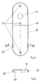
- the transmission nut 28 essentially consists of a circular disk 49 with a diameter corresponding to the larger diameter of the bore 42 of the inner part 22.
- the disc 49 protruding driver pins 50 and 51 are inserted above the front.
- the disk 49 is provided with an essentially cylindrical extension 52, the diameter of which corresponds to the small diameter of the bore 42 and which has a radially projecting arm 53.
- the thickness of the disc 49 including lug 52 corresponds to the thickness of the inner part 22.
- the transmission nut 28 is inserted into the bore 42 so that the disc in the portion with the large diameter, the lug 52 in the Small diameter section and arm 53 is located in extension 43.
- the extension 52 and the arm 53 can also protrude beyond the inner part 22 into a corresponding hole in the door 7 (FIG. 2).
- the transmission nut 28 also has a center hole 54 (FIGS. 8, 10) for the non-rotatable mounting of the bolt actuating member 9.
- the center hole 54 has a square cross section, which corresponds to the reduced cross section of a front end 55 (FIG. 2) of the bolt actuating member 9.
- the control nut 26 contains a cylindrical bushing on its rear side 57, on the front of which a disk-shaped, approximately semicircular control cam 58 is formed, the radius of which is larger than that of the bushing 57.
- the diameter of the bushing 57 corresponds essentially to the diameter of the cylindrical part of the bearing bore 36 of the inner part 22.
- the bushing 57 is inserted into the bearing bore 36 from the front until the cam 58 flies to its step 39 and in its extension 37 is arranged. Front ends of the control cam 58 serve as control cams 59 and 60.
- the control nut 26 also has in its rear part a receiving opening 61 for the latch actuating element 8 (FIG. 2) in such a way that it can be rotated back and forth to a limited extent in the receiving opening 61.
- a center hole 61a for receiving the neck 25 (FIG. 2) of the handle 10.
- These walls 62 are evenly spaced in the circumferential direction, for example each extend over approximately 60 ° and are delimited at both ends by flat, somewhat inwardly projecting stop surfaces 63 and 64, respectively.
- the extensions of the two stop surfaces 63, 64 of each wall 62 each close an angle of a preselected size, e.g. of approx. 30 °.
- the latch actuator 8 can be rotated clockwise by approximately 60 ° from a position in which it lies against the stop surfaces 63 into a position in which it lies against the stop surfaces 64.
- the control nut 26 can be rotated counterclockwise relative to the latch actuating element 8 from a position in which the latch actuating element 8 lies against the stop surfaces 63.
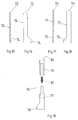
- FIG. 13 shows the latch actuating element 8. It has a continuously square cross section and, according to FIG. 2, projects through the latch nut 2, a corresponding passage in the handle 11 arranged on the outside of the door and the receiving opening 61.
- the end of the latch actuating member 8 projecting through the receiving opening 61 has a bore 65 with an internal thread, into which an extension 66 with a corresponding external thread can be screwed, which is formed on the front of an insert 67 which follows Fig. 2 in a receiving opening of the handle 10 arranged on the inside of the door rotatably and for this purpose, for example, is also penetrated by the pin 27 and together with the neck 25 of the control nut 26 projects into the center hole 61a.
- the bearing bore 36 (FIG. 5) and the bore 42 are at a defined distance from one another.
- the control cams 59, 60 (FIG. 12) and the driver pins 50, 51 (FIG. 8) are also at defined distances from one another.
- the slides 70, 71 serve for the mechanical coupling of the control cams 59, 60 or driver pins 50, 51 in the manner to be described below and therefore have a length adapted to the respective distance.
- a slide 76 according to FIG. 19 can also be used, which has a lower part 77 with a foot 78 corresponding to the foot 75 and an upper part 79 with an end surface 80 corresponding to the end face 73.
- a compression spring 81 can be arranged between the two parts 77, 79, which strives to axially shift the two slide parts 77, 79 in opposite directions.
- the slides 70, 71 and 76 rest on the guide surfaces 40 of the inner part 22.
- the neck section 25 is first inserted into the bearing bore 32 of the lower part 18 from the front until the handle end face is supported on the latter.
- the control nut 26 is then pulled with its receiving opening 61 onto the latch actuator 8 screwed to the insert 67 until its control curve 58 comes to rest on the inside of the lower part 18 and the front end of the insert 67 in the receiving opening 61a.
- the pin 27 is inserted from the rear of the lower part 18 into a corresponding, not shown, oblique bore of the control nut 26 and pushed through this into a coaxially aligned, formed in the handle 10 and / or its insert 67 further bore to connect the handle 10 to the control nut 26 in a rotationally fixed manner.
- the various parts assume the position relative to one another as shown in FIG. 20.
- the latch actuating element 8 bears with its side faces against the stop faces 63 of the receiving opening 61, while the slide 70 rests on the one hand with its end face 72 on the control cam 59 and on the other hand with its foot 74 on the driver pin 50.
- the latch is under the influence of a conventional lock spring in the closed position.
- the bolt is withdrawn.
- the slide 71 rests with its foot 75 on the driving pin 51, while its upper end face 73 is at a preselected distance from the associated control cam 60.
- the handle 10 To move the bolt into its closed position, the handle 10 must be moved from the position shown in FIG. 20 through an angle d of e.g. about 30 ° to the position shown in FIG. 21 are pivoted. During this movement, the bushing 57 rotates freely on the latch actuator 8 without influencing it, because the stop surfaces 63 move away from the side surfaces of the latch actuator 8 and the stop surfaces 64 would not rest on these side surfaces until after an angle of rotation of approximately 60 ° .
- the threaded portions of parts 8 and 67 (Fig. 13) also allow this rotation because the insert 67 is not fully tightened in the bore 65.
- the distance traveled by the slide 71 is greater than the distance traveled by the slide 70 in the same rotation of the transmission nut 28, because the driving pin 51, as shown in FIGS. 20 to 22, has a greater distance than the driving pin 50 from the axis of rotation of the transmission nut 28.
- the position of the handle assumed in the closed position of the bolt (FIG. 21) is clearly recognizable and also widely visible, particularly when a door handle is used.
- the handle 10 retains this position due to the usual friction conditions even if it is a door handle which exerts a certain torque on the control nut 26.
- the control nut 26 again performs an idle stroke until its stop surfaces 63 rest against the side surfaces of the latch actuating element 8 without it to influence while at the same time her control cam 60 pushes the slide 71 down.
- the bolt is only partially retracted because, because of the large distance of the driving pin 51 from the axis of rotation of the transmission nut 28, a rotation of the control nut 26 by 30 ° is not sufficient to turn the transmission nut 28 back by 90 °.
- the width of the end faces 72.73 or feet 74.75 of the slide 70.71 is selected such that they can interact with the associated control cams 59.60 or driver pins 50.51 in all the positions described.
- the latch can be opened or closed in the usual way by means of the handle 11.
- the bolt actuating element 8 rotates freely in the receiving opening 61 of the control nut 26 without influencing it, so that the inner handle 10 can at most reach the position shown in FIG. 22 due to its weight.
- An actuation of the bolt is not possible with the handle 11 because rotation in the opposite direction is blocked by the latch nut.
- An actuation of the bolt is at best possible from the outside in that the viewing plate 16 is actuated with an emergency opening tool.
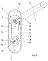
- the radially projecting arm 53 (FIG. 10) can serve in the described function to limit the angle of rotation for the transmission nut 28 to 90 ° by mounting the arm in the extension 43 (FIG. 5) of the bore 42 of the inner part 22 in this way is that it stops at the ends of the rotational movement on the associated stops 44.
- the position according to FIG. 24 corresponds to that according to FIG. 21 with the difference that the two parts 77 and 79 of the slide 76 are held at a certain distance by the compression spring 81, so that they can be displaced axially relative to one another. If the handle 10 is now rotated back by the angle d, the slide parts 77, 79 are first brought into contact with each other under further tension of the compression spring 81, and only then does the transmission nut 28 and the bolt actuating member 9 partially rotate back via the slide 76 and the driving pin 51 (Fig. 23). If the handle 10 is then rotated through the angle in the sense of opening the latch, the control cam 60 first acts directly via the slide 76, i.e. positively on the driving pin 51.
- the function described with reference to FIGS. 23 to 25 is up to a maximum angle of rotation the latch nut 2 of, for example, 30 ° is possible, in which case the two slide parts 77, 79 remain in mutual contact until the bolt is fully retracted.
- the maximum angle of rotation can be determined, for example, by the distance of the driving pin 51 from the axis of rotation of the transmission nut 28, which is smaller in the embodiment according to FIGS. 23 to 25 than in the embodiment according to FIGS. 20 to 22.
- the invention is not restricted to the exemplary embodiments described, which can be modified in many ways.
- Other transmission mechanisms can also prove to be useful if, unlike the narrow door plate shown, there is more space for its accommodation.
- the invention is not limited to the fact that the handle 10 is pivoted in the closed position of the bolt by an angle of 30 ° with respect to the zero position. Rather, the transmission ratio of the transmission mechanism can also be chosen so that there are smaller or larger swivel angles, a swivel angle of 90 ° also being conceivable. Furthermore, it is possible to rotate the latch actuator 8 by other means, but to connect it axially immovably to the handle 10. Finally, the lower parts 18 and inner parts 22 can be designed in any other suitable shape.
- Corresponding control nuts 26 are furthermore expediently provided for right and left opening doors.
- the cross-section of the receiving opening 61 can also have other contours instead of the star or cross shape shown, in particular also be square, but somewhat larger than the cross-sectional area of the latch actuating member 8.
- Receiving openings of this type are generally known for other purposes (DE 38 33 757 A1, DE 38 33 758 A1).
- the parts of the fitting according to the invention described are preferably predominantly made of plastic by injection molding.
Landscapes
- Lock And Its Accessories (AREA)
- Ladders (AREA)
- Soil Working Implements (AREA)
- Forklifts And Lifting Vehicles (AREA)
- Mutual Connection Of Rods And Tubes (AREA)
- Joining Of Building Structures In Genera (AREA)
- Gripping Jigs, Holding Jigs, And Positioning Jigs (AREA)
- Clamps And Clips (AREA)
- Securing Of Glass Panes Or The Like (AREA)
Applications Claiming Priority (2)
| Application Number | Priority Date | Filing Date | Title |
|---|---|---|---|
| DE4300999A DE4300999A1 (de) | 1993-01-15 | 1993-01-15 | Beschlag für ein eine Falle und einen Riegel aufweisendes Schloß |
| DE4300999 | 1993-01-15 |
Publications (3)
| Publication Number | Publication Date |
|---|---|
| EP0606877A2 true EP0606877A2 (fr) | 1994-07-20 |
| EP0606877A3 EP0606877A3 (fr) | 1994-11-23 |
| EP0606877B1 EP0606877B1 (fr) | 1997-10-01 |
Family
ID=6478297
Family Applications (1)
| Application Number | Title | Priority Date | Filing Date |
|---|---|---|---|
| EP94100268A Expired - Lifetime EP0606877B1 (fr) | 1993-01-15 | 1994-01-11 | Ferrure pour une serrure avec un pêne demi-tour et un pêne dormant |
Country Status (5)
| Country | Link |
|---|---|
| EP (1) | EP0606877B1 (fr) |
| AT (1) | ATE158838T1 (fr) |
| DE (2) | DE4300999A1 (fr) |
| DK (1) | DK0606877T3 (fr) |
| ES (1) | ES2110637T3 (fr) |
Cited By (4)
| Publication number | Priority date | Publication date | Assignee | Title |
|---|---|---|---|---|
| EP1004728A3 (fr) * | 1998-11-24 | 2003-04-02 | Rohrbacher Scholesserwarenfabrik Wilh. Grundmann Gesellschaft m.b.H. | Serrure anti-panique |
| US7150809B2 (en) | 2003-04-15 | 2006-12-19 | Basf Aktiengesellschaft | Thermal separating process |
| US11111698B2 (en) * | 2016-12-05 | 2021-09-07 | Endura Products, Llc | Multipoint lock |
| WO2021251896A3 (fr) * | 2020-06-12 | 2022-02-10 | Stendals El Ab | Adaptateur destiné à un dispositif de verrouillage |
Family Cites Families (9)
| Publication number | Priority date | Publication date | Assignee | Title |
|---|---|---|---|---|
| US2862750A (en) * | 1956-03-05 | 1958-12-02 | Robert M Minke | Door latch operating mechanism |
| GB1432817A (en) * | 1973-09-26 | 1976-04-22 | Gkn Stenman Ab | Locking device incorporating a lock case an escutcheon housing and a door handle |
| GB1467539A (en) * | 1975-02-05 | 1977-03-16 | Tre Corp | Panic proof lock |
| US3999789A (en) * | 1976-01-15 | 1976-12-28 | Kysor Industrial Corporation | Lock |
| US4809526A (en) * | 1988-07-20 | 1989-03-07 | Shen Chao C | Cartridge of a panic proof lock |
| DE3833757C2 (de) * | 1988-10-05 | 1998-06-10 | Wilke Heinrich Hewi Gmbh | Schloß für eine Tür od. dgl. |
| DE3833758C2 (de) * | 1988-10-05 | 1998-05-28 | Wilke Heinrich Hewi Gmbh | Beschlag mit einer Handhabe zur Betätigung der Schloßnuß eines in eine Tür od. dgl. eingesetzten Schlosses |
| US4979767A (en) * | 1990-01-08 | 1990-12-25 | Taiwan Fu Hsing Industry Co., Ltd. | Opening device for a double lock |
| US5077992A (en) * | 1991-05-28 | 1992-01-07 | Frank Su | Door lock set with simultaneously retractable deadbolt and latch |
-
1993
- 1993-01-15 DE DE4300999A patent/DE4300999A1/de not_active Withdrawn
-
1994
- 1994-01-11 ES ES94100268T patent/ES2110637T3/es not_active Expired - Lifetime
- 1994-01-11 DK DK94100268.5T patent/DK0606877T3/da active
- 1994-01-11 AT AT94100268T patent/ATE158838T1/de not_active IP Right Cessation
- 1994-01-11 EP EP94100268A patent/EP0606877B1/fr not_active Expired - Lifetime
- 1994-01-11 DE DE59404175T patent/DE59404175D1/de not_active Expired - Fee Related
Cited By (4)
| Publication number | Priority date | Publication date | Assignee | Title |
|---|---|---|---|---|
| EP1004728A3 (fr) * | 1998-11-24 | 2003-04-02 | Rohrbacher Scholesserwarenfabrik Wilh. Grundmann Gesellschaft m.b.H. | Serrure anti-panique |
| US7150809B2 (en) | 2003-04-15 | 2006-12-19 | Basf Aktiengesellschaft | Thermal separating process |
| US11111698B2 (en) * | 2016-12-05 | 2021-09-07 | Endura Products, Llc | Multipoint lock |
| WO2021251896A3 (fr) * | 2020-06-12 | 2022-02-10 | Stendals El Ab | Adaptateur destiné à un dispositif de verrouillage |
Also Published As
| Publication number | Publication date |
|---|---|
| DE4300999A1 (de) | 1994-07-21 |
| EP0606877A3 (fr) | 1994-11-23 |
| ATE158838T1 (de) | 1997-10-15 |
| DK0606877T3 (da) | 1998-05-25 |
| DE59404175D1 (de) | 1997-11-06 |
| EP0606877B1 (fr) | 1997-10-01 |
| ES2110637T3 (es) | 1998-02-16 |
Similar Documents
| Publication | Publication Date | Title |
|---|---|---|
| DE3943715C2 (de) | Drehstangenverschluß | |
| DE3447748C2 (fr) | ||
| DE3010703A1 (de) | Tuerschliesseranordnung | |
| DE4201069C2 (de) | Getriebe für ein Türschloß, insbesondere ein Rauchschutztürschloß | |
| DE3941923C2 (de) | Getriebe für Drehkipptüren | |
| DE3833758C2 (de) | Beschlag mit einer Handhabe zur Betätigung der Schloßnuß eines in eine Tür od. dgl. eingesetzten Schlosses | |
| DE69207320T2 (de) | Verbesserter Schloss mit einer Einrichtung zwecks Öffnen im Notfall | |
| EP0556553B1 (fr) | Système de commande d'une serrure de porte, notamment pour serrure de porte anti-panique | |
| DE3631516C2 (fr) | ||
| DE19531680C1 (de) | Betätigungsvorrichtung | |
| EP0534089B1 (fr) | Dispositif de commande pour les tiges coulissantes d'une serrure d'une fenêtre ou d'une porte | |
| EP0606877B1 (fr) | Ferrure pour une serrure avec un pêne demi-tour et un pêne dormant | |
| DE2259917B2 (de) | Fallenbetätigungsvorrichtung | |
| DE9208528U1 (de) | Einsteckschloß für eine Haustür oder Wohnungseingangstür | |
| DE69003357T2 (de) | Motorisiertes Scharnier, zu öffnen, zu verschliessen, zu verriegeln und zu entriegeln. | |
| DE2313611A1 (de) | Tuerschloss | |
| DE69807608T2 (de) | Schliessvorrichtung, insbesondere Einsteckschloss mit einer Falle, für eine Fenstertür oder dergleichen | |
| DE2518318A1 (de) | Verriegelungsvorrichtung | |
| DE3833757C2 (de) | Schloß für eine Tür od. dgl. | |
| EP1671001B1 (fr) | Serrure | |
| DE69807801T2 (de) | Verriegelungsvorrichtung, insbesondere Einsteckschloss für den Flügel einer Tür oder eines Fensters | |
| DE4200868A1 (de) | Zusatz-schliesseinrichtung fuer fenster | |
| DE102020128077A1 (de) | Beschlag mit einem links-/rechts-umstellbaren Mitnehmer | |
| EP1024240B1 (fr) | Dispositif de verrouillage | |
| DE3305209C2 (fr) |
Legal Events
| Date | Code | Title | Description |
|---|---|---|---|
| PUAI | Public reference made under article 153(3) epc to a published international application that has entered the european phase |
Free format text: ORIGINAL CODE: 0009012 |
|
| AK | Designated contracting states |
Kind code of ref document: A2 Designated state(s): AT BE CH DE DK ES FR IT LI NL SE |
|
| PUAL | Search report despatched |
Free format text: ORIGINAL CODE: 0009013 |
|
| AK | Designated contracting states |
Kind code of ref document: A3 Designated state(s): AT BE CH DE DK ES FR IT LI NL SE |
|
| 17P | Request for examination filed |
Effective date: 19950511 |
|
| 17Q | First examination report despatched |
Effective date: 19950704 |
|
| GRAG | Despatch of communication of intention to grant |
Free format text: ORIGINAL CODE: EPIDOS AGRA |
|
| GRAH | Despatch of communication of intention to grant a patent |
Free format text: ORIGINAL CODE: EPIDOS IGRA |
|
| GRAH | Despatch of communication of intention to grant a patent |
Free format text: ORIGINAL CODE: EPIDOS IGRA |
|
| GRAA | (expected) grant |
Free format text: ORIGINAL CODE: 0009210 |
|
| AK | Designated contracting states |
Kind code of ref document: B1 Designated state(s): AT BE CH DE DK ES FR IT LI NL SE |
|
| REF | Corresponds to: |
Ref document number: 158838 Country of ref document: AT Date of ref document: 19971015 Kind code of ref document: T |
|
| REG | Reference to a national code |
Ref country code: CH Ref legal event code: EP |
|
| REF | Corresponds to: |
Ref document number: 59404175 Country of ref document: DE Date of ref document: 19971106 |
|
| ITF | It: translation for a ep patent filed | ||
| ET | Fr: translation filed | ||
| PG25 | Lapsed in a contracting state [announced via postgrant information from national office to epo] |
Ref country code: LI Free format text: LAPSE BECAUSE OF NON-PAYMENT OF DUE FEES Effective date: 19980131 Ref country code: CH Free format text: LAPSE BECAUSE OF NON-PAYMENT OF DUE FEES Effective date: 19980131 |
|
| REG | Reference to a national code |
Ref country code: ES Ref legal event code: FG2A Ref document number: 2110637 Country of ref document: ES Kind code of ref document: T3 |
|
| REG | Reference to a national code |
Ref country code: DK Ref legal event code: T3 |
|
| PLBE | No opposition filed within time limit |
Free format text: ORIGINAL CODE: 0009261 |
|
| STAA | Information on the status of an ep patent application or granted ep patent |
Free format text: STATUS: NO OPPOSITION FILED WITHIN TIME LIMIT |
|
| REG | Reference to a national code |
Ref country code: CH Ref legal event code: PL |
|
| 26N | No opposition filed | ||
| PGFP | Annual fee paid to national office [announced via postgrant information from national office to epo] |
Ref country code: FR Payment date: 20000111 Year of fee payment: 7 |
|
| PGFP | Annual fee paid to national office [announced via postgrant information from national office to epo] |
Ref country code: SE Payment date: 20000113 Year of fee payment: 7 |
|
| PGFP | Annual fee paid to national office [announced via postgrant information from national office to epo] |
Ref country code: BE Payment date: 20000119 Year of fee payment: 7 |
|
| PGFP | Annual fee paid to national office [announced via postgrant information from national office to epo] |
Ref country code: ES Payment date: 20000120 Year of fee payment: 7 |
|
| PGFP | Annual fee paid to national office [announced via postgrant information from national office to epo] |
Ref country code: AT Payment date: 20000124 Year of fee payment: 7 |
|
| PGFP | Annual fee paid to national office [announced via postgrant information from national office to epo] |
Ref country code: DK Payment date: 20000125 Year of fee payment: 7 |
|
| PGFP | Annual fee paid to national office [announced via postgrant information from national office to epo] |
Ref country code: NL Payment date: 20000131 Year of fee payment: 7 |
|
| PGFP | Annual fee paid to national office [announced via postgrant information from national office to epo] |
Ref country code: DE Payment date: 20000328 Year of fee payment: 7 |
|
| PG25 | Lapsed in a contracting state [announced via postgrant information from national office to epo] |
Ref country code: DK Free format text: LAPSE BECAUSE OF NON-PAYMENT OF DUE FEES Effective date: 20010111 Ref country code: AT Free format text: LAPSE BECAUSE OF NON-PAYMENT OF DUE FEES Effective date: 20010111 |
|
| PG25 | Lapsed in a contracting state [announced via postgrant information from national office to epo] |
Ref country code: SE Free format text: LAPSE BECAUSE OF NON-PAYMENT OF DUE FEES Effective date: 20010112 Ref country code: ES Free format text: LAPSE BECAUSE OF NON-PAYMENT OF DUE FEES Effective date: 20010112 |
|
| PG25 | Lapsed in a contracting state [announced via postgrant information from national office to epo] |
Ref country code: BE Free format text: LAPSE BECAUSE OF NON-PAYMENT OF DUE FEES Effective date: 20010131 |
|
| BERE | Be: lapsed |
Owner name: HEINRICH WILKE G.M.B.H. HEWI Effective date: 20010131 |
|
| PG25 | Lapsed in a contracting state [announced via postgrant information from national office to epo] |
Ref country code: NL Free format text: LAPSE BECAUSE OF NON-PAYMENT OF DUE FEES Effective date: 20010801 |
|
| EUG | Se: european patent has lapsed |
Ref document number: 94100268.5 |
|
| REG | Reference to a national code |
Ref country code: DK Ref legal event code: EBP |
|
| PG25 | Lapsed in a contracting state [announced via postgrant information from national office to epo] |
Ref country code: FR Free format text: LAPSE BECAUSE OF NON-PAYMENT OF DUE FEES Effective date: 20010928 |
|
| NLV4 | Nl: lapsed or anulled due to non-payment of the annual fee |
Effective date: 20010801 |
|
| PG25 | Lapsed in a contracting state [announced via postgrant information from national office to epo] |
Ref country code: DE Free format text: LAPSE BECAUSE OF NON-PAYMENT OF DUE FEES Effective date: 20011101 |
|
| REG | Reference to a national code |
Ref country code: FR Ref legal event code: ST |
|
| REG | Reference to a national code |
Ref country code: ES Ref legal event code: FD2A Effective date: 20021016 |
|
| PG25 | Lapsed in a contracting state [announced via postgrant information from national office to epo] |
Ref country code: IT Free format text: LAPSE BECAUSE OF NON-PAYMENT OF DUE FEES;WARNING: LAPSES OF ITALIAN PATENTS WITH EFFECTIVE DATE BEFORE 2007 MAY HAVE OCCURRED AT ANY TIME BEFORE 2007. THE CORRECT EFFECTIVE DATE MAY BE DIFFERENT FROM THE ONE RECORDED. Effective date: 20050111 |