EP0606879B1 - Vorrichtung mit einem Abfallbehälter, einem Deckel dafür und einem Deckel-Öffnungsmechanismus für Haushalts- und Sanitärzwecke - Google Patents
Vorrichtung mit einem Abfallbehälter, einem Deckel dafür und einem Deckel-Öffnungsmechanismus für Haushalts- und Sanitärzwecke Download PDFInfo
- Publication number
- EP0606879B1 EP0606879B1 EP94100270A EP94100270A EP0606879B1 EP 0606879 B1 EP0606879 B1 EP 0606879B1 EP 94100270 A EP94100270 A EP 94100270A EP 94100270 A EP94100270 A EP 94100270A EP 0606879 B1 EP0606879 B1 EP 0606879B1
- Authority
- EP
- European Patent Office
- Prior art keywords
- lid
- waste container
- sub
- assembly
- webs
- Prior art date
- Legal status (The legal status is an assumption and is not a legal conclusion. Google has not performed a legal analysis and makes no representation as to the accuracy of the status listed.)
- Expired - Lifetime
Links
- 230000007246 mechanism Effects 0.000 title abstract description 9
- 239000002699 waste material Substances 0.000 claims description 70
- 230000005484 gravity Effects 0.000 claims description 2
- 210000001331 nose Anatomy 0.000 claims 2
- 238000005192 partition Methods 0.000 claims 1
- 210000002105 tongue Anatomy 0.000 description 12
- 230000000694 effects Effects 0.000 description 3
- 210000003127 knee Anatomy 0.000 description 3
- 229910000831 Steel Inorganic materials 0.000 description 2
- 239000010959 steel Substances 0.000 description 2
- 238000013459 approach Methods 0.000 description 1
- 238000010276 construction Methods 0.000 description 1
- 238000001746 injection moulding Methods 0.000 description 1
- 238000009434 installation Methods 0.000 description 1
- 210000002414 leg Anatomy 0.000 description 1
- 230000000873 masking effect Effects 0.000 description 1
- 230000000149 penetrating effect Effects 0.000 description 1
- 230000002093 peripheral effect Effects 0.000 description 1
- 239000002689 soil Substances 0.000 description 1
- 230000009182 swimming Effects 0.000 description 1
Images




Classifications
-
- B—PERFORMING OPERATIONS; TRANSPORTING
- B65—CONVEYING; PACKING; STORING; HANDLING THIN OR FILAMENTARY MATERIAL
- B65F—GATHERING OR REMOVAL OF DOMESTIC OR LIKE REFUSE
- B65F1/00—Refuse receptacles; Accessories therefor
- B65F1/14—Other constructional features; Accessories
- B65F1/141—Supports, racks, stands, posts or the like for holding refuse receptacles
- B65F1/1421—Supports, racks, stands, posts or the like for holding refuse receptacles having means for operating lids or covers
-
- Y—GENERAL TAGGING OF NEW TECHNOLOGICAL DEVELOPMENTS; GENERAL TAGGING OF CROSS-SECTIONAL TECHNOLOGIES SPANNING OVER SEVERAL SECTIONS OF THE IPC; TECHNICAL SUBJECTS COVERED BY FORMER USPC CROSS-REFERENCE ART COLLECTIONS [XRACs] AND DIGESTS
- Y10—TECHNICAL SUBJECTS COVERED BY FORMER USPC
- Y10S—TECHNICAL SUBJECTS COVERED BY FORMER USPC CROSS-REFERENCE ART COLLECTIONS [XRACs] AND DIGESTS
- Y10S220/00—Receptacles
- Y10S220/908—Trash container
Definitions
- the invention relates to a device specified in the preamble of claim 1 Genus.
- the bottom of the container is inclined from front to back and down so that the input First of all, waste along the bottom into a rear, the container in its The container part holding the rest position slips.
- the one to ensure this effect required inclination of the container bottom is with a reduction in usable Container volume connected.
- Such opening mechanisms are prone to failure and are common bad to use, since the entire device is usually easy to slide on stands on the ground and therefore does not always take the position that is easy Allows access to the foot pedal.
- the foot pedal bend and / or the linkage is easy to use, causing the opening mechanism becomes unusable.
- One consequence of this is that devices that have lids and therefore have preferred waste containers for hygienic reasons, often remain unused, especially in hospitals, schools, swimming pools or Like. Is perceived as annoying.
- the invention has for its object a device of the type mentioned To create genre that fixed in the bathroom, toilet or the like. At a fixed predetermined location can be and their opening mechanism structurally simple and therefore little is prone to failure and with no special precautions to ensure the rest position when filling with waste are required.
- the invention has the advantage that the waste container with a Hand or with a knee swiveling movement to open the Lid can be brought to the required position. It is possible to do the opening movement by means of simple wedge or sliding surfaces, so that there is a simple, stable construction results.
- the substructure 1 shown in FIGS. 1 to 4 contains one in the exemplary embodiment rectangular, flat, substantially plane-parallel plate 2 with offset bores 3, or the like for fastening the plate 2 to a wall.
- the heads of fastening screws and additional washers can be used if necessary.
- the plate 2 At her lateral longitudinal edges is the plate 2 with vertically protruding, narrow, parallel side walls 4 arranged to each other, which are somewhat at their rear ends have protruding support arms 5, at the front ends of which are bent upwards Guide lugs 6 (Fig. 3) are attached.
- protruding support arms 5 At the upper ends of the side walls 4 are also further protruding arms 7 are provided, in which U-shaped open at the bottom Cutouts 8 are formed.
- the arms 7 are at their front, upper Corners with holes 9 and at their upper, rear ends with a plurality of over the entire width of the plate 2 distributed cylindrical bearing pin 10 (Fig. 3) provided, which are formed on the upper end of the plate 2 and the upper limits form rectangular cutouts 11.
- a recess 12 is made, the the upper and lower edges are each provided with an undercut 13 or 14 (FIG. 3). Furthermore, at least one at the lower edge of the plate 2 and between the support arms 5 elastically resilient tongue 16 provided with an undercut 15. Finally, on the inside of at least one side wall 4, one of these is facing forward protruding, also resilient tongue 17 fastened with a recess 18.
- the waste container 19 shown in FIGS. 5 to 9 is essentially cylindrical, however, provided with a floor and a flat rear wall 20 (Fig. 6). Of this protrude two plate-shaped retaining webs 21 vertically backwards, which in one Distance between the support arms 5 and the arms 7 (Fig. 1) are arranged corresponding distance.
- the holding webs 21 are provided at their lower ends with guide surfaces 22 (FIG. 8), which run obliquely upwards and backwards from the rear wall 20 and downwards Directional holding lugs 23, each at the lower ends of the holding webs 21 Make a stop.
- the holding webs 21 each have one vertically upwardly projecting guide web 24 which is essentially the width the cutouts 8 (FIG. 3) have a corresponding width.
- the holding webs 21 25 and 26 so suspended on the support arms 5 that their retaining lugs 23 behind the Grip guide posts 6 and strike them.
- the holding webs 21 are not only held in the vertical direction, but also secured against being pulled forward.
- the height of the holding webs 21 is dimensioned such that the guide webs 24, if the holding webs 21 are supported on the support arms 5 (Fig. 25, 26) with their upper Immerse the ends just so deep into the cutouts 8 that the retaining webs 21 also on their upper ends against pulling out or unintentional falling out of the Substructure 1 are secured.
- the guide webs 24 are so big Clearances from the rear wall 20 that the outer lower ends of the arms 7th (Fig. 3) of the substructure 1 in the spaces thus formed.
- the rear wall 20 At its upper end is the rear wall 20 with at least one protruding over it Actuator 25 (Fig. 7 and 8) provided in the form of a narrow bar, the preferably has an oblique wedge surface 26 at its upper end, which with the back wall 20 an angle of e.g. 45 ° forms, begins at the top of the same and from there diagonally upwards and backwards.
- Actuator 25 Fig. 7 and 8
- the back wall 20 an angle of e.g. 45 ° forms, begins at the top of the same and from there diagonally upwards and backwards.
- two are Actuators 25 provided between the holding webs 21 and near these are arranged (Fig. 5 and 6).
- At least one of the holding webs 21 is inclined provided slot 27 which is arranged and designed so that it at the Function of the waste container 19 still to be described constantly on the recess 18th an associated resilient tongue 17 (Fig. 3) of the substructure 1 aligned is.
- the waste container 19 can have a rotating one at its upper end Centering web 28 may be provided for a cover 31, which is subsequently based on FIGS 14 is explained in more detail.
- the edge 33 is formed as a flat rear wall 35. Are there the dimensions of the lid 31 selected so that this in the closed state by means of Centering webs 28, 34 are centered on the waste container 19 (Fig. 25, 26) and the Outside of the edge 33 a flush continuation of the outer shell of the waste container 19 forms.
- the cover 31 On the rear wall 35 of the cover 31 there is at least one extension 36 projecting downwards attached, which has a transverse bore 37 which is from a continuous journal 38 (Fig. 25,26) can be penetrated, which serves there, with its ends in the holes 9 (Fig. 3) of the arms 7 to be inserted and thereby the lid 31 pivoted in the Store substructure 1.
- a continuous journal 38 Fig. 25,26
- two such approaches 36 are provided that have such a distance that when the cover 31 is mounted between and come to lie directly next to the arms 7, in which case the continuous one Bearing pin 38 also through two short, only immediately adjacent holes 9.37 penetrating journal can be replaced.
- the bores 9 can preferably be designed as elongated holes to the centering of the lid 31 on the Waste bin 19 to compensate for design-related tolerance deviations.
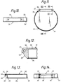
- the lugs 36 are provided on their back with oblique sliding surfaces 39, which with the rear wall 35 of the lid 31 substantially the same angle as that Form the wedge surface 26 (FIG. 8) of the waste container 19 and from the lower edge of the rear wall 35 run diagonally backwards and upwards.
- the sliding surfaces 39 are in the exemplary embodiment arranged and designed so that they rest on the waste container 19 26 are at least partially supported on the wedge surfaces 26. At the rear ends, the sliding surfaces 39 are essentially perpendicular to them Stops 40 provided (see. In particular Fig. 12) with the actuators 25 (Fig. 27) can cooperate.
- the lugs 36 are covered to the rear by a cover 41 (FIG. 13), the one lying in the extension of the lid base 32 and one has another section bent downwards.
- the width of the cover 41 corresponds essentially to the distance of the shoulder 36 (FIG. 14).
- a cover cap 45 (FIG. 15 until 20).
- This contains two parallel side walls 46 and 47 and one perpendicular to it running floor 48.
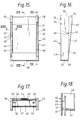
- Parallel to each side wall 46,47 is also an intermediate wall 49.50 provided, the distance between the walls assigned in pairs 46.49 or 15 or 18 is slightly larger than the thickness of the side walls the substructure 1 and the corresponding thickness of the holding webs 21 of the waste container 19 corresponds.
- the slots 51 formed by the walls 46, 49 and 47.50 (Fig. 15) also have a center distance which is the center distance of the side walls 4 and Holding webs 21 corresponds.
- the Cover cap 45 so on the substructure already attached to a wall or the like put on that their support arms 5 and arms 7 come to lie in the slots 51 and the bottom 48 is arranged just below the support arms 5.
- the cap 45 now pressed toward the wall or the like, the undercuts 15 of the tongues snap 16 in the recesses 52 and the undercuts of the tongues 54, 55 behind the Undercuts 13,14, whereby the cap 45 is a tight fit on the Substructure 1 receives.
- the rear edges of the side walls 46, 47 form and the floor 48 preferably a flat surface, which od for abutting the wall. The like.
- the intermediate walls 49, 50 of the cover cap 45 have where they are put on the substructure 1, the tongues 17 come to rest, in each case a recess 60 (Fig. 16,19).
- the cutouts 18 (FIG. 3) of the tongues 17 are made before the cover cap 45 is installed and the waste container 19 also anti-theft elements 61 in the form of Cross pins with pin or disk-shaped heads inserted, as in Fig. 25 and 26 is indicated schematically, and preferably by means of snap connections or the like in secured this.
- the retaining webs 21 of the waste container 19 are now inserted into the slots 51, that the guide webs 24 (Fig. 8) enter the cutouts 8 (Fig. 3), whereupon the Waste container 19 is slightly lowered to the lower ends of the holding webs 21 to drop the support arms 5 (Fig. 25,26) that the retaining lugs 23 behind the guide lugs 6 grab and the waste container 19 a rest position in the substructure 1 occupies.
- the retaining webs 21 press when they are inserted into the slots 51 first the tongues 17 provided on the substructure 1 (FIG.
- the lid 31 Before or after the assembly of the waste container 19, the lid 31 is assembled by corresponding journal 38 from the side through the holes 56 of the cap 45 are inserted into the bores 9 (FIG. 3) of the substructure 1.
- the front of the cap 45 is covered with a front wall 57, which accordingly 16 and 19 substantially parallel to the rear edges of the Side walls 46,47 and the bottom 48 runs.
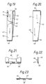
- the slots 51 are on their upper and lower ends covered by masking strips 58, 59, which in particular 16 and 20 can be seen.
- the storage container 65 for special Hygiene bag is used. Up this storage container 65 by another Cover 66 (Fig. 21 to 23) closed.
- This essentially consists of a cover plate 67, which are provided on their rear side with slotted bearing eyelets 68 (FIG. 22) at the same intervals as the bearing pins 10 (FIGS. 1 and 3) of the substructure 1 are arranged and can be clipped on to the cover 66 pivoted on the Attach substructure, the bearing eyelets 68 at least partially in the Cutouts 11 (Fig. 1) can occur.
- the cross section of the cover plate 67 corresponds essentially the cross section of the upper end of the reservoir 65.
- the cover plate 67 is provided with a recess 69, which on the one hand as Grip recess can be used when actuating the cover 66, but also the View of the user of the waste container 19 onto the interior of the storage container 65 or releases the hygiene bags inside.
- the cover 31 In the rest position of the waste container 19 suspended in the substructure 1 (FIG. 24, 25) the cover 31 is in its closed position.
- the holding lugs 23 grip behind the guide lugs 6, while the guide webs 24 slightly into the cutouts 8 protrude.
- the waste container 19 is essentially impenetrable to the sides, since its retaining webs 21 are held in the slots 51 (FIG. 15) of the cap 45, the despite the fact that parts 13, 14, 15, 52, 54 and 55 are just snap locks form, can not be dismantled when the waste container 19 is attached.
- the sliding surfaces 39 of the cover 31 correspond to FIG. 26 at least partially on the wedge surfaces 26 of the waste container 19.
- An opening of the lid 31 is effected in that the waste container 19 is pivoted in the lower region in the direction of an arrow v in accordance with FIG. 27, which can be done by hand, but preferably also with the knee, for which purpose the waste container 19 is expediently in Knee height is arranged. Because of this pivoting, the guide surface 22 moves according to FIG. 27 along the guide shoulder 6, as a result of which the waste container 19 is raised somewhat in the direction of an arrow w and at the same time the guide webs 24 enter the cutouts 8 deeper.
- the wedge surfaces 26 or the upper ends of the actuating elements 25 act on the sliding surfaces 39 of the cover 31, as a result of which the latter is pivoted upward about the spatially fixed axis of the bearing pins 38 in the direction of an arrow x while opening the waste container 19.
- the pivoting in the lower region of the waste container 19 in the direction of arrow v also has the advantageous effect that the container opening released by the cover 31 is pivoted in the direction of the user. If the waste container 19 is then released, its gravity causes the steps described to proceed in reverse order until the rest position according to FIGS. 24 to 26 is reached again.
- the pivoting movement of the waste container 19 required to open the lid 31 only needs to be a few degrees, which can be achieved by dimensioning the Side walls 46,47 and the front wall of the cap can be ensured.
- the lid 31 is also closed automatically
- the position of the stops 40 (Fig. 27) is preferably chosen so that the lid 31 opened wide enough because of the stop of the stops 40 on the Actuators 25, however, never reach the 90 ° position or via this can be swung out.
- the length of the slots 27 is chosen so that the waste container 19 can perform the pivoting movements described.
- the waste container 19 is to be emptied, when it is in the raised position according to FIG. 27, a steel pin is inserted from the outside into the bores 62 (FIGS. 15, 16) in order to push the anti-theft elements 61 out of the slots 27, and Thereafter, the waste container 19 is pivoted forwards in the opposite direction to the arrow v , as a result of which the retaining lugs 23 can first be pulled out of the slots 51 of the cover cap 45 and then the guide webs 24 downwards out of the cutouts 8.
- the invention is not restricted to the exemplary embodiment described, which is based on can be modified in many ways. This is especially true for training, number and arrangement of the various parts of the opening mechanism for the lid 31. Apart from that, it would be possible, for example, the lower part of the substructure 1 as an elbow in such a way that one of their legs instead of on the wall Soil can be attached.
- the waste container 19 and the other parts described are preferably made of Plastic and made by injection molding.
Landscapes
- Engineering & Computer Science (AREA)
- Mechanical Engineering (AREA)
- Refuse Receptacles (AREA)
- Centrifugal Separators (AREA)
Applications Claiming Priority (2)
| Application Number | Priority Date | Filing Date | Title |
|---|---|---|---|
| DE4300998 | 1993-01-15 | ||
| DE4300998A DE4300998A1 (de) | 1993-01-15 | 1993-01-15 | Vorrichtung mit einem Abfallbehälter, einem Deckel dafür und einem Deckel-Öffnungsmechanismus für Haushalts- und Sanitärzwecke |
Publications (2)
| Publication Number | Publication Date |
|---|---|
| EP0606879A1 EP0606879A1 (de) | 1994-07-20 |
| EP0606879B1 true EP0606879B1 (de) | 1998-04-15 |
Family
ID=6478296
Family Applications (1)
| Application Number | Title | Priority Date | Filing Date |
|---|---|---|---|
| EP94100270A Expired - Lifetime EP0606879B1 (de) | 1993-01-15 | 1994-01-11 | Vorrichtung mit einem Abfallbehälter, einem Deckel dafür und einem Deckel-Öffnungsmechanismus für Haushalts- und Sanitärzwecke |
Country Status (6)
| Country | Link |
|---|---|
| US (1) | US5492238A (da) |
| EP (1) | EP0606879B1 (da) |
| AT (1) | ATE165067T1 (da) |
| DE (2) | DE4300998A1 (da) |
| DK (1) | DK0606879T3 (da) |
| ES (1) | ES2118266T3 (da) |
Families Citing this family (17)
| Publication number | Priority date | Publication date | Assignee | Title |
|---|---|---|---|---|
| TW276236B (en) * | 1994-10-05 | 1996-05-21 | Nifco Inc | Cap |
| USD388578S (en) * | 1996-06-13 | 1997-12-30 | Bobrick Washroom Equipment, Inc. | Sanitary napkin disposal |
| AU134280S (en) | 1996-09-26 | 1998-07-06 | Cws Int A G | Refuse bin |
| USD401708S (en) | 1997-07-07 | 1998-11-24 | Bobrick Washroom Equipment, Inc. | Waste receptacle |
| GB2334880A (en) * | 1998-03-02 | 1999-09-08 | Hospital Metalcraft Limited | Lidded Bin |
| USD415641S (en) * | 1998-06-19 | 1999-10-26 | Douglas Endress Roberts | Dispenser support |
| US6974948B1 (en) | 2000-05-26 | 2005-12-13 | Brent Mark R | Perimetric detection system |
| AU2001263460A1 (en) | 2000-05-26 | 2001-12-11 | Mark R. Brent | Perimetric detection system and automated container |
| ITRE20000109A1 (it) * | 2000-11-06 | 2002-05-06 | Stil Casa S N C Di Marcheselli | Pattumiera con coperchio a ribalta |
| AU2003266880A1 (en) * | 2002-09-13 | 2004-04-30 | Whirlpool Canada Inc. | Device and process for processing organic waste |
| US6837394B2 (en) | 2002-11-08 | 2005-01-04 | Patricia Ann Nnamani | Sanitary disposal unit |
| USD490581S1 (en) | 2003-03-03 | 2004-05-25 | Daniel J. Keithly | Trash can with bag removal assist vent |
| US20090090711A1 (en) * | 2007-09-28 | 2009-04-09 | Barcham Clifton | Recycle container for curbside refuse pickup |
| US20120325992A1 (en) * | 2011-06-07 | 2012-12-27 | Keshock Michael E | Aerial-lift-platform accessory |
| US8833596B2 (en) * | 2012-09-13 | 2014-09-16 | Berlin Packaging, Llc | Mounting bracket for a container |
| CA150701S (en) * | 2012-10-12 | 2016-04-07 | Fumacare Ltd | Sanitary container |
| US12070126B2 (en) | 2022-03-02 | 2024-08-27 | Interdesign, Inc. | Brackets, bins, and shelves |
Family Cites Families (10)
| Publication number | Priority date | Publication date | Assignee | Title |
|---|---|---|---|---|
| US1485496A (en) * | 1922-11-13 | 1924-03-04 | Thomas G Elliott | Pantry receptacle |
| US1594535A (en) * | 1926-01-30 | 1926-08-03 | Ingward J Lindbeck | Container |
| US2427335A (en) * | 1945-03-09 | 1947-09-16 | Vega C Antonia | Support for kitchen containers |
| US2754991A (en) * | 1952-07-01 | 1956-07-17 | Adlake Co | Ash receivers |
| US3383035A (en) * | 1966-12-20 | 1968-05-14 | Lawrence E. Smithers | Receptacle |
| NL6905006A (da) * | 1969-04-01 | 1970-10-05 | ||
| DE3400153A1 (de) * | 1984-01-04 | 1985-07-11 | Hammerlit Gmbh, 2950 Leer | Vorrichtung zur aufnahme von abfall |
| FR2587188B1 (fr) * | 1985-09-18 | 1988-04-15 | Allibert Sa | Corbeille a papier et bride adaptee a la fixation de la corbeille |
| NL9000192A (nl) * | 1990-01-25 | 1991-08-16 | Bammens Bv | Inrichting voor het verplaatsbaar opnemen van een houder. |
| DE4101285C2 (de) * | 1991-01-17 | 1999-03-25 | Eckart Roth | Vorrichtung zur Entsorgung von Abfall |
-
1993
- 1993-01-15 DE DE4300998A patent/DE4300998A1/de not_active Withdrawn
-
1994
- 1994-01-11 DK DK94100270T patent/DK0606879T3/da active
- 1994-01-11 AT AT94100270T patent/ATE165067T1/de active
- 1994-01-11 ES ES94100270T patent/ES2118266T3/es not_active Expired - Lifetime
- 1994-01-11 DE DE59405669T patent/DE59405669D1/de not_active Expired - Lifetime
- 1994-01-11 EP EP94100270A patent/EP0606879B1/de not_active Expired - Lifetime
- 1994-01-18 US US08/182,658 patent/US5492238A/en not_active Expired - Fee Related
Also Published As
| Publication number | Publication date |
|---|---|
| ES2118266T3 (es) | 1998-09-16 |
| DE4300998A1 (de) | 1994-07-21 |
| ATE165067T1 (de) | 1998-05-15 |
| US5492238A (en) | 1996-02-20 |
| DK0606879T3 (da) | 1999-02-08 |
| EP0606879A1 (de) | 1994-07-20 |
| DE59405669D1 (de) | 1998-05-20 |
Similar Documents
| Publication | Publication Date | Title |
|---|---|---|
| EP0606879B1 (de) | Vorrichtung mit einem Abfallbehälter, einem Deckel dafür und einem Deckel-Öffnungsmechanismus für Haushalts- und Sanitärzwecke | |
| DE3612567C2 (da) | ||
| DE69411192T2 (de) | Schloss für kassetten für die herstellung von schubladenschränken | |
| DE2412114A1 (de) | Vorrichtung zum verriegeln bestimmter von mehreren herausziehbaren aufbewahrungseinheiten bei einer aufbewahrungseinrichtung, z.b. einem schrank | |
| DE1963591A1 (de) | Wandkonsole | |
| DE60110954T2 (de) | Kassetten und Schublade für Schubladenschränke | |
| DE2241174A1 (de) | Schwenkschubladen-konstruktion | |
| DE1810003B2 (de) | Gehäuse fur einen Plattenspieler | |
| DE69402777T2 (de) | Stapelbarer Karton mit Frontöffnung | |
| DE8900997U1 (de) | Regal mit Seitenwänden aus mehrlagigem Faltmaterial | |
| EP0675997A1 (de) | Vorrichtung zum sperren von türen | |
| DE4342362C1 (de) | Tragestruktur zum Ausrichten eines Möbels, insbesondere für höhenverstellbare Sockel für Einzelschränke und/oder Schränke einer Schrankwand | |
| DE102020129597B4 (de) | Klappe, insbesondere für einen Abfalleimer, und Abfalleimer | |
| DE9417521U1 (de) | Transportbehälter | |
| DE60102644T2 (de) | Betätigungsvorrichtung für einen Fensterschliessmechanismus | |
| DE2717096C2 (de) | Schrankelement mit einer Kipplade | |
| DE4434933C2 (de) | Verschluß zur zentralen Ver- und Entriegelung von Schubladen | |
| DE10222046C5 (de) | Spüle | |
| DE3001819C2 (da) | ||
| DE19549037A1 (de) | Deckel für Müllbehälter | |
| DE7712073U1 (de) | Schrankelement mit einer kipplade | |
| DE8505439U1 (de) | Blockieranlage für einen verstellbaren Behälter | |
| DE4107992A1 (de) | Seifenspender | |
| DE3221073A1 (de) | Schublade | |
| CH413277A (de) | Brief- und Warenablieferungskasten |
Legal Events
| Date | Code | Title | Description |
|---|---|---|---|
| PUAI | Public reference made under article 153(3) epc to a published international application that has entered the european phase |
Free format text: ORIGINAL CODE: 0009012 |
|
| AK | Designated contracting states |
Kind code of ref document: A1 Designated state(s): AT BE CH DE DK ES FR IT LI NL SE |
|
| 17P | Request for examination filed |
Effective date: 19950120 |
|
| 17Q | First examination report despatched |
Effective date: 19960531 |
|
| GRAG | Despatch of communication of intention to grant |
Free format text: ORIGINAL CODE: EPIDOS AGRA |
|
| GRAG | Despatch of communication of intention to grant |
Free format text: ORIGINAL CODE: EPIDOS AGRA |
|
| GRAH | Despatch of communication of intention to grant a patent |
Free format text: ORIGINAL CODE: EPIDOS IGRA |
|
| GRAH | Despatch of communication of intention to grant a patent |
Free format text: ORIGINAL CODE: EPIDOS IGRA |
|
| GRAA | (expected) grant |
Free format text: ORIGINAL CODE: 0009210 |
|
| AK | Designated contracting states |
Kind code of ref document: B1 Designated state(s): AT BE CH DE DK ES FR IT LI NL SE |
|
| REF | Corresponds to: |
Ref document number: 165067 Country of ref document: AT Date of ref document: 19980515 Kind code of ref document: T |
|
| REG | Reference to a national code |
Ref country code: CH Ref legal event code: EP |
|
| REF | Corresponds to: |
Ref document number: 59405669 Country of ref document: DE Date of ref document: 19980520 |
|
| ITF | It: translation for a ep patent filed | ||
| REG | Reference to a national code |
Ref country code: CH Ref legal event code: NV Representative=s name: E. BLUM & CO. PATENTANWAELTE |
|
| EN | Fr: translation not filed | ||
| REG | Reference to a national code |
Ref country code: ES Ref legal event code: FG2A Ref document number: 2118266 Country of ref document: ES Kind code of ref document: T3 |
|
| EN | Fr: translation not filed |
Free format text: BO 98/37 PAGES: 233 IL Y A LIEU DE SUPPRIMER: LA MENTION DE LA NON REMISE DE CETTE TRADUCTION LA MENTION DE LA REMISE DE CETTE TRADUCTION EST PUBLIEE DANS LE PRESENT BOPI |
|
| ET | Fr: translation filed | ||
| REG | Reference to a national code |
Ref country code: DK Ref legal event code: T3 |
|
| PLBE | No opposition filed within time limit |
Free format text: ORIGINAL CODE: 0009261 |
|
| STAA | Information on the status of an ep patent application or granted ep patent |
Free format text: STATUS: NO OPPOSITION FILED WITHIN TIME LIMIT |
|
| 26N | No opposition filed | ||
| REG | Reference to a national code |
Ref country code: CH Ref legal event code: PFA Owner name: HEWI HEINRICH WILKE GMBH Free format text: HEWI HEINRICH WILKE GMBH#PROFESSOR BIERSTRASSE 1-5#D-34454 AROLSEN (DE) -TRANSFER TO- HEWI HEINRICH WILKE GMBH#PROFESSOR BIERSTRASSE 1-5#D-34454 AROLSEN (DE) |
|
| PGFP | Annual fee paid to national office [announced via postgrant information from national office to epo] |
Ref country code: ES Payment date: 20080218 Year of fee payment: 15 Ref country code: DK Payment date: 20080115 Year of fee payment: 15 |
|
| PGFP | Annual fee paid to national office [announced via postgrant information from national office to epo] |
Ref country code: SE Payment date: 20080104 Year of fee payment: 15 |
|
| EUG | Se: european patent has lapsed | ||
| REG | Reference to a national code |
Ref country code: DK Ref legal event code: EBP |
|
| REG | Reference to a national code |
Ref country code: ES Ref legal event code: FD2A Effective date: 20090112 |
|
| PG25 | Lapsed in a contracting state [announced via postgrant information from national office to epo] |
Ref country code: ES Free format text: LAPSE BECAUSE OF NON-PAYMENT OF DUE FEES Effective date: 20090112 |
|
| PG25 | Lapsed in a contracting state [announced via postgrant information from national office to epo] |
Ref country code: DK Free format text: LAPSE BECAUSE OF NON-PAYMENT OF DUE FEES Effective date: 20090731 |
|
| PG25 | Lapsed in a contracting state [announced via postgrant information from national office to epo] |
Ref country code: SE Free format text: LAPSE BECAUSE OF NON-PAYMENT OF DUE FEES Effective date: 20090112 |
|
| PGFP | Annual fee paid to national office [announced via postgrant information from national office to epo] |
Ref country code: IT Payment date: 20110125 Year of fee payment: 18 Ref country code: NL Payment date: 20110117 Year of fee payment: 18 |
|
| PGFP | Annual fee paid to national office [announced via postgrant information from national office to epo] |
Ref country code: BE Payment date: 20110104 Year of fee payment: 18 |
|
| BERE | Be: lapsed |
Owner name: HEINRICH WILKE G.M.B.H. *HEWI Effective date: 20120131 |
|
| REG | Reference to a national code |
Ref country code: NL Ref legal event code: V1 Effective date: 20120801 |
|
| PG25 | Lapsed in a contracting state [announced via postgrant information from national office to epo] |
Ref country code: IT Free format text: LAPSE BECAUSE OF NON-PAYMENT OF DUE FEES Effective date: 20120111 |
|
| PG25 | Lapsed in a contracting state [announced via postgrant information from national office to epo] |
Ref country code: BE Free format text: LAPSE BECAUSE OF NON-PAYMENT OF DUE FEES Effective date: 20120131 |
|
| PG25 | Lapsed in a contracting state [announced via postgrant information from national office to epo] |
Ref country code: NL Free format text: LAPSE BECAUSE OF NON-PAYMENT OF DUE FEES Effective date: 20120801 |
|
| PGFP | Annual fee paid to national office [announced via postgrant information from national office to epo] |
Ref country code: FR Payment date: 20130213 Year of fee payment: 20 Ref country code: DE Payment date: 20130328 Year of fee payment: 20 Ref country code: CH Payment date: 20130123 Year of fee payment: 20 |
|
| PGFP | Annual fee paid to national office [announced via postgrant information from national office to epo] |
Ref country code: AT Payment date: 20130111 Year of fee payment: 20 |
|
| REG | Reference to a national code |
Ref country code: DE Ref legal event code: R071 Ref document number: 59405669 Country of ref document: DE |
|
| REG | Reference to a national code |
Ref country code: DE Ref legal event code: R071 Ref document number: 59405669 Country of ref document: DE |
|
| REG | Reference to a national code |
Ref country code: CH Ref legal event code: PL |
|
| REG | Reference to a national code |
Ref country code: AT Ref legal event code: MK07 Ref document number: 165067 Country of ref document: AT Kind code of ref document: T Effective date: 20140111 |
|
| PG25 | Lapsed in a contracting state [announced via postgrant information from national office to epo] |
Ref country code: DE Free format text: LAPSE BECAUSE OF EXPIRATION OF PROTECTION Effective date: 20140114 |