EP0606901A2 - Appareil électrophotographique - Google Patents
Appareil électrophotographique Download PDFInfo
- Publication number
- EP0606901A2 EP0606901A2 EP94100376A EP94100376A EP0606901A2 EP 0606901 A2 EP0606901 A2 EP 0606901A2 EP 94100376 A EP94100376 A EP 94100376A EP 94100376 A EP94100376 A EP 94100376A EP 0606901 A2 EP0606901 A2 EP 0606901A2
- Authority
- EP
- European Patent Office
- Prior art keywords
- electrostatic latent
- holding member
- latent image
- image holding
- removing roller
- Prior art date
- Legal status (The legal status is an assumption and is not a legal conclusion. Google has not performed a legal analysis and makes no representation as to the accuracy of the status listed.)
- Granted
Links
Images











Classifications
-
- G—PHYSICS
- G03—PHOTOGRAPHY; CINEMATOGRAPHY; ANALOGOUS TECHNIQUES USING WAVES OTHER THAN OPTICAL WAVES; ELECTROGRAPHY; HOLOGRAPHY
- G03G—ELECTROGRAPHY; ELECTROPHOTOGRAPHY; MAGNETOGRAPHY
- G03G15/00—Apparatus for electrographic processes using a charge pattern
- G03G15/06—Apparatus for electrographic processes using a charge pattern for developing
- G03G15/08—Apparatus for electrographic processes using a charge pattern for developing using a solid developer, e.g. powder developer
-
- G—PHYSICS
- G03—PHOTOGRAPHY; CINEMATOGRAPHY; ANALOGOUS TECHNIQUES USING WAVES OTHER THAN OPTICAL WAVES; ELECTROGRAPHY; HOLOGRAPHY
- G03G—ELECTROGRAPHY; ELECTROPHOTOGRAPHY; MAGNETOGRAPHY
- G03G15/00—Apparatus for electrographic processes using a charge pattern
- G03G15/06—Apparatus for electrographic processes using a charge pattern for developing
- G03G15/08—Apparatus for electrographic processes using a charge pattern for developing using a solid developer, e.g. powder developer
- G03G15/095—Removing excess solid developer, e.g. fog preventing
-
- B—PERFORMING OPERATIONS; TRANSPORTING
- B82—NANOTECHNOLOGY
- B82Y—SPECIFIC USES OR APPLICATIONS OF NANOSTRUCTURES; MEASUREMENT OR ANALYSIS OF NANOSTRUCTURES; MANUFACTURE OR TREATMENT OF NANOSTRUCTURES
- B82Y15/00—Nanotechnology for interacting, sensing or actuating, e.g. quantum dots as markers in protein assays or molecular motors
-
- G—PHYSICS
- G03—PHOTOGRAPHY; CINEMATOGRAPHY; ANALOGOUS TECHNIQUES USING WAVES OTHER THAN OPTICAL WAVES; ELECTROGRAPHY; HOLOGRAPHY
- G03G—ELECTROGRAPHY; ELECTROPHOTOGRAPHY; MAGNETOGRAPHY
- G03G15/00—Apparatus for electrographic processes using a charge pattern
- G03G15/06—Apparatus for electrographic processes using a charge pattern for developing
- G03G15/08—Apparatus for electrographic processes using a charge pattern for developing using a solid developer, e.g. powder developer
- G03G15/09—Apparatus for electrographic processes using a charge pattern for developing using a solid developer, e.g. powder developer using magnetic brush
- G03G15/0921—Details concerning the magnetic brush roller structure, e.g. magnet configuration
-
- G—PHYSICS
- G03—PHOTOGRAPHY; CINEMATOGRAPHY; ANALOGOUS TECHNIQUES USING WAVES OTHER THAN OPTICAL WAVES; ELECTROGRAPHY; HOLOGRAPHY
- G03G—ELECTROGRAPHY; ELECTROPHOTOGRAPHY; MAGNETOGRAPHY
- G03G2215/00—Apparatus for electrophotographic processes
- G03G2215/06—Developing structures, details
- G03G2215/0602—Developer
- G03G2215/0604—Developer solid type
- G03G2215/0614—Developer solid type one-component
- G03G2215/0621—Developer solid type one-component powder cloud
-
- G—PHYSICS
- G03—PHOTOGRAPHY; CINEMATOGRAPHY; ANALOGOUS TECHNIQUES USING WAVES OTHER THAN OPTICAL WAVES; ELECTROGRAPHY; HOLOGRAPHY
- G03G—ELECTROGRAPHY; ELECTROPHOTOGRAPHY; MAGNETOGRAPHY
- G03G2215/00—Apparatus for electrophotographic processes
- G03G2215/06—Developing structures, details
- G03G2215/0634—Developing device
- G03G2215/0636—Specific type of dry developer device
- G03G2215/0639—Without donor member (i.e. developing housing slides on latent image-carrying member)
Definitions
- the present invention relates to an electrophtographic apparatus which can be used in printers, facsimile equipment or the like.
- a two-component development method using a developer formed of toner and carrier has so far been widely used in electrophotography, but in recent years development of a mono-component development method has been in progress in order to make image forming units smaller and less costly.
- Fig. 28 shows the electrophotographic apparatus which uses such a mono-component development method and was disclosed by the inventors of the present invention in the Japanese Patent Application "Heisei 3-345990".
- item 1 is an electrostatic latent image holding member of an organic photoconductor drum which has phthalocyanine dispersed in a binder resin of polyester group.
- Item 2 is a magnet with the axis thereof fixed coaxially with the organic photoconductor drum 1.
- Item 3 is a corona charger for charging the organic photoconductor drum 1.
- Item 4 is a grid electrode for controlling charge potential of the organic photoconductor drum 1.
- Item 5 is signal light.
- Item 6 is a developer reservoir.
- Item 7 is a magnetic one-component toner serving as developer.
- Item 8 is a damper for making smooth the flow of the toner 7 inside the developer reservoir 6, and also preventing the toner 7 from being packed due to its own weight and filling between the organic photoconductor drum 1 and a removing roller 9.
- Item 9 is a removing roller made of aluminum and having a magnet 10 therein.
- Item 11 is an AC high voltage power source for applying a voltage to the removing roller 9.
- Item 12 is a scraper made of polyester film for scraping toner from the removing roller 9.
- Item 13 is a transfer corona charger for transferring toner images formed on the organic photoconductor drum 1 to paper.
- the organic photoconductor drum 1 is charged to -500 V by means of the corona charger 3 and the grid electrode 4.
- An electrostatic latent image is formed by irradiating laser light 5 on the organic photoconductor drum 1.
- the toner 7 is deposited on the surface of the organic photoconductor drum 1 by magnetic force in the developer reservoir 6.
- the organic photoconductor drum 1 is caused to pass the front of the removing roller 9.
- an AC voltage of 750 0-p (1 kHz in frequency) with a DC voltage of -350 V superimposed thereon is applied to the removing roller 9 from the AC high voltage power source 11.
- the toner 7 is removed from the organic photoconductor drum 1 to the removing roller 9, and toner images with a positive-negative picture reversal are left only on the image areas of the organic photoconductor drum 1.
- the toner 7 deposited on the removing roller 9 which is rotating in the arrow direction is scraped off by the scraper 12, and returned to the developer reservoir 6 for use in the image forming steps to follow.
- the toner images thus formed on the organic photoconductor drum 1 are transfered to paper (not shown in Fig. 28) by the transfer charger 13, and then thermally fixed by means of fixing equipment (not shown in Fig. 28).
- the image density of solid image is low under a high temperature and high humidity environment (33°C , 85 %RH, for example), and background development is found to increase gradually on the printed images.
- the object of the present invention is to provide an electrophotographic apparatus for reproducing prints with high image density and excellent image quality not showing any non-uniformity in image density and any background development, either.
- One of the features of the present invention is an electrophotographic apparatus comprising a magnetic developer, an electrostatic latent image holding member which rotates in a specified direction, a removing roller which is set up at a position with a specified distance apart from the surface of said electrostatic latent image holding member and rotates in the direction opposite to the rotation of said electrostatic latent image holding member, a developer reservoir for supplying said magnetic developer to the surface of said electrostatic latent image holding member, a means for supplying an AC voltage to said removing roller to remove the developer staying on non-image areas of said electrostatic latent image holding member, and a magnetic field generating means installed by fixing inside said electrostatic latent image holding member for producing two magnetic poles having polarity different from each other on the surface of said electrostatic latent image holding member in the vicinity of image developing areas where said electrostatic latent image holding member comes closest to said removing roller.
- an electrophotographic apparatus comprising a magnetic developer, an electrostatic latent image holding member which rotates in a specified direction, a removing roller which is set up at position with a specified distance apart from the surface of said electrostatic latent image holding member and rotates in the direction opposite to the rotation of said electrostatic latent image holding member, a developer reservoir for supplying said magnetic developer to the surface of said electrostatic latent image holding member, a means for supplying an AC voltage to said removing roller to remove the developer staying on non-image areas of said electrostatic latent image holding member, and a magnetic field generating means installed by fixing inside said removing roller for producing two magnetic poles with polarity different from each other on the surface of said removing roller in the vicinity of image development areas where said electrostatic latent image holding member comes closest to said removing roller.
- Still another feature of the present invention is an electrophotographic apparatus comprising a magnetic developer, an electrostatic latent image holding member which has on its surface a means for increasing friction force against said developer and rotates in a specified direction, a removing roller which is set up at a position with a specified distance apart from the surface of said electrostatic latent image holding member and rotates in the direction opposite to the rotation of said electrostatic latent image holding member, a developer reservoir for supplying said magnetic developer to the surface of said electrostatic latent image holding member, a means for supplying an AC voltage to said removing roller to remove the developer staying on non-image areas of said electrostatic latent image holding member, and a magnetic field generating means installed by fixing inside said electrostatic latent image holding member for producing a magnetic field on the surface of said electrostatic latent image holding member in the vicinity of image developing areas where said electrostatic latent image holding member comes closest to said removing roller.
- Still further feature of the present invention is an electrophotographic apparatus comprising a magnetic developer, an electrostatic latent image holding member which rotates in a specified direction, a removing roller which has on its surface a means for increasing friction force against said developer, is set up at a position with a specified distance apart from the surface of said electrostatic latent image holding member, and rotates in the direction opposite to the rotation of said electrostatic latent image holding member, a developer reservoir for supplying said magnetic developer to the surface of said electrostatic latent image holding member, a means for supplying an AC voltage to said removing roller for removing the developer staying on non-image areas of said electrostatic latent image holding member, and a magnetic field generating means installed by fixing inside said electrostatic latent image holding member for producing a magnetic field on the surface of said electrostatic latent image holding member in the vicinity of image developing areas where said electrostatic latent image holding member comes closest to said removing roller.
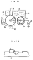
- Fig. 1 is a schematic illustration to show the structure of a first exemplary embodiment of the present invention of an electrophotographic apparatus.
- Fig. 2 is an enlarged view of the vicinity of the developing areas shown in Fig. 1 for explaining the effects of the present invention.
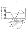
- Fig. 3 is a chart of the magnetic flux density distribution observed in the vertical direction on the surface of the electrostatic latent image holding members of a first, fifth, and sixth exemplary embodiment of the present invention, respectively.
- Fig. 4 is a schematic illustration for explaining the arrangement of the magnetic poles formed by magnets as described in a first exemplary embodiment of the present invention.
- Fig. 5 shows waveforms of the AC voltage as used in a first, second, third, fourth, fifth, sixth, seventh, eighth, and ninth exemplary embodiment of the present invention, respectively.
- Fig. 6 is a schematic illustration to show the structure of a second exemplary embodiment of the present invention of an electrophotographic apparatus.
- Fig. 7 is a chart of the magnetic flux density distribution observed in the vertical direction on the surface of the electrostatic latent image holding member of a second, and seventh exemplary embodiment of the present invention, respectively.
- Fig. 8 is a schematic illustration for explaining the arrangement of the magnetic poles formed by magnets as described in a second exemplary embodiment of the present invention.
- Fig. 9 is a schematic illustration to show the structure of a third exemplary embodiment of the present invention of an electrophotographic apparatus.
- Fig. 10 is an enlarged view of the vicinity of the developing areas shown in Fig. 9 for explaining the effects of the present invention.
- Fig. 11 is a chart of the magnetic flux density distribution observed in the vertical direction on the surface of the removing rollers of a third, fifth, and seventh exemplary embodiment of the present invention, respectively.
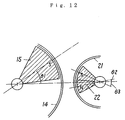
- Fig. 12 is a schematic illustration for explaining the arrangement of the magnetic poles formed by magnets as described in a third exemplary embodiment of the present invention.
- Fig. 13 is a schematic illustration to show the structure of a fourth exemplary embodiment of the present invention of an electrophotographic apparatus.
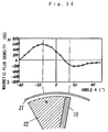
- Fig. 14 is a chart of the magnetic flux density distribution observed in the vertical direction on the surface of the removing rollers of a fourth, and sixth exemplary embodiment of the present invention, respectively.
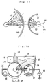
- Fig. 15 is a schematic illustration for explaining the arrangement of the magnetic poles formed by magnets as described in a fourth exemplary embodiment of the present invention.
- Fig. 16 is a schematic illustration to show the structure of a fifth exemplary embodiment of the present invention of an electrophotographic apparatus.
- Fig. 17 is a schematic illustration for explaining the arrangement of the magnetic poles formed by magnets as described in a fifth exemplary embodiment of the present invention.
- Fig. 18 is a schematic illustration to show the structure of a sixth exemplary embodiment of the present invention of an electrophotographic apparatus.
- Fig. 19 is a schematic illustration for explaining the arrangement of the magnetic poles formed by magnets as described in a sixth exemplary embodiment of the present invention.
- Fig. 20 is a schematic illustration to show the structure of a seventh exemplary embodiment of the present invention of an electrophotographic apparatus.
- Fig. 21 is a schematic illustration for explaining the arrangement of the magnetic poles formed by magnets as described in a seventh exemplary embodiment of the present invention.
- Fig. 22 is a schematic illustration to show the structure of an eighth exemplary embodiment of the present invention of an electrophotographic apparatus.
- Fig. 23 is a schematic illustration to show the structure of a ninth exemplary embodiment of the present invention of an electrophotographic apparatus.
- Fig. 24 is an enlarged cross-sectional view of the surface of the removing roller as described in a ninth exemplary embodiment of the present invention.
- Fig. 25 is a schematic illustration to show the structure of a tenth exemplary embodiment of the present invention of an electrophotographic apparatus.
- Fig. 26 is a schematic illustration to show the structure of an eleventh exemplary embodiment of the present invention of an electrophotographic apparatus.
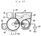
- Fig. 27 is a schematic illustration to show the structure of a twelfth exemplary embodiment of the present invention of an electrophotographic apparatus.
- Fig. 28 is a schematic illustration to show the structure of a prior art electrophotographic apparatus.
- FIG. 1 is a schematic illustration to show the structure of Example 1.
- item 14 is a cylindrical electrostatic latent image holding member (30 mm in diameter), which has its surface disposed with an organic photoconductor prepared by dispersing phthalocyanine in a binder resin of polyester group, and rotates at a peripheral speed of 30 mm/s.
- Item 15 is a magnet which is fixed coaxially with said electrostatic latent image holding member 14 formed of non-rotary two poles, and serving as a magnetic field generating means. There are no particular restrictions imposed on the magnet 15, and a permanent magnet or an electromagnet can be used.
- Item 16 is a corona charger for charging negatively the electrostatic latent image holding member 14.
- Item 17 is a grid electrode for controlling the charge potential of the electrostatic latent image holding member 14.
- Item 18 is signal light for forming electrostatic latent images.
- Item 19 is a developer reservoir.
- Item 20 is a developer, e.g. a magnetic mono-component negatively chargeable toner with an average particle diameter of 12 ⁇ m.
- Item 21 is a cylindrical removing roller (16 mm in diameter) made of aluminum, and serving as an electrode, which is installed at a specified distance apart from the electrostatic latent image holding member 14 and rotates at a peripheral speed of 30 mm/s in the direction opposite to the rotation of the electrostatic latent image holding member 14.
- Item 22 is a non-rotary magnet fixed coaxially with the removing roller 21, serving as a magnetic field generating means. There are no specific restrictions imposed on the magnet 22, and a permanent magnet or an electromagnet can be used.
- Item 23 is an AC high voltage power source for applying a voltage to the removing roller 21.
- Item 24 is a scraper made of polyester film for scraping off the toner attached on the removing roller 21.
- Item 25 is a transfer corona charger for transferring the images, which are formed on the electrostatic latent image holding member by deposition of toner, onto paper.
- Item 26 is a cleaner for removing the toner that remained on the electrostatic latent image holding member 14 after transferring the images.
- Fig. 3 shows a chart of magnetic flux density distribution observed in the vertical direction on the surface of the electrostatic latent image holding member 14 in the vicinity of the magnet 15.
- the peak values of the magnetic flux density measure -700 Gs (S-pole), and 500 Gs (N-pole), respectively.
- the peak value of magnetic flux density of the magnet 22 measures 600 Gs (N-pole) at the surface of the removing roller 21.
- Fig. 4 shows the positional relation between the magnets 15 and 22 both installed inside the electrostatic latent image holding member 14 and the removing roller 21, respectively.
- the range of said angle ⁇ 1 is desirable to be 15° ⁇ ⁇ 1 ⁇ 50° and the range of 20° ⁇ ⁇ 1 ⁇ 45°, in particular, is the most suitable range.
- the range of ⁇ 2 is desirable to be 0° ⁇ ⁇ 2 ⁇ 30° and the range of 5° ⁇ ⁇ 2 ⁇ 20°, in particular, is the most suitable range.
- the range of ⁇ 3 is desirable to be -30° ⁇ ⁇ 3 ⁇ 10° and the range of -20° ⁇ ⁇ 3 ⁇ 0°, in particular, is the most suitable range.
- composition of the developer used in present example was 70 % wt. of polyester resin, 25 % wt. of ferrite, 3 % wt. of carbon black, and 2 % wt. of oxycarboxylic acid metal complex with 0.4 % wt. of colloidal silica added further.
- the electrostatic latent image holding member 14 was charged to - 500 V by means of the corona charger 16 and the grid electrode 17. (The applied voltage was - 4 kV and the grid electrode voltage was - 500 V.) Then, an electrostatic latent image was formed by irradiation of the laser signal light 18 on said electrostatic latent image holding member 14. At this time, the exposure potential (V r ) of the electrostatic latent image holding member 14 was - 100 V. Next, the one-component magnetic toner was attached on the surface of said electrostatic latent image holding member 14 in the developer reservoir 19 by the magnetic force of the magnet 15. At this time, the toner was charged to about -3 ⁇ C/g.
- the toner attached on the electrostatic latent image holding member 14 was then formed into a brush-like shape along the magnetic force which was produced by the magnet 15 and disposed in the peripheral direction of the electrostatic latent image holding member 14.
- the said toner attached in the brush-like shape was transported by the frictional force caused by rotation of the electrostatic latent image holding member 14.
- the magnetic toner which was aligned along the magnetic force lines produced by magnetic field looks like a brush, and is referred to as a magnetic brush.
- the electrostatic latent image holding member 14 attached with a toner layer passed the front of the removing roller 21, the surface of which was located at a distance of 300 ⁇ m from that of the electrostatic latent image holding member 14.
- the toner attached on the removing roller 21 was formed into a brush-like shape along the magnetic force which was produced by the magnet 22 and disposed in the peripheral direction of the removing roller.
- the toner attached on the removing roller 21 was transported by the rotation made in the direction indicated by an arrow in Fig. 1, scraped off by the scraper 24, and returned into the developer reservoir 19. It was observed at the upper area of the S-pole on the surface of the electrostatic latent image holding member 14 that the toner was in a fierce turbulence.
- the toner images thus formed on the electrostatic latent image holding member 14 were transferred on paper (not shown in Fig.1) by means of the transfer corona charger 25. Then, after thermal fixing by means of fixing equipment (not shown in Fig. 1), printed images were obtained.
- this particular exemplary embodiment of the present invention features a structure comprising a fixed and non-rotary magnet, e.g. a magnetic field generating means, which is installed inside a rotary electrostatic latent image holding member, and produces two magnetic poles having polarity opposite to each other on the surface of the electrostatic latent image holding member in the vicinity of the developing areas where the electrostatic latent image holding member comes closest to the removing roller.
- a fixed and non-rotary magnet e.g. a magnetic field generating means
- FIG. 2 is an enlarged view to show schematically the vicinity of the developing areas of the electrophotographic apparatus as illustrated in Fig. 1.
- the toner is aligned in a brush-like shape along the magnetic force lines generated by the magnet 15 in the peripheral direction of the electrostatic latent image holding member 14 to form a magnetic brush 20a.
- the transporting force of the toner 20 exerted by the electrostatic latent image holding member 14 does not work on the individual particles of the toner, which are forming the first layer of the toner and are in direct contact with the surface of the electrostatic latent image holding member, but works on the entire magnetic brush which is a collection of the toner particles put together by magnetic force, the transporting force to carry the toner will be remarkably intensified. Besides, the unevenness in transporting force due to the non-uniformity in frictional force among the individual toner particles will be rectified. As a result, the toner furnished to the electrostatic latent image holding member 14 is supplied to the developing areas in abundance and in a stabilized manner, and excellent picture quality showing a high image density and not having any non-uniformity of density.
- FIG. 6 differs from that of Fig. 1 in the magnetic field generating means. More specifically, the magnet 15 installed inside the electrostatic latent image holding member has one magnetic pole, and a magnetic plate 27 has been added, instead, to the magnet 15 at the side opposite to the direction of rotation thereof. As the magnetic plate 27 is used such a substance readily magnetized by an external magnetic field as iron or the like.
- the other parts of Fig. 6 are the same as those in Fig. 1. Therefore, the same explanation as was made on the symbols used in Fig. 1 applies to those of Fig. 6.
- Fig. 7 shows a chart of the magnetic flux density distribution of the magnet 15 and the magnetic plate 27 observed in the vertical direction on the surface of the electrostatic latent image holding member 14.
- the peak values of the magnetic flux density measure -300 Gs (magnetic plate), and 500 Gs (N-pole), respectively.
- the magnetic plate 27 is magnetized by the magnet 15, and a magnetic pole opposite to the one formed on the surface of the magnet 25 is produced on the surface of the magnet 27.
- Fig. 8 shows the arrangement of the magnet 15 and the magnetic plate 27 both installed inside the electrostatic latent image holding member 14, and the magnet 22 inside the removing roller 21.
- the range of said angle ⁇ 1 is desirable to be 15° ⁇ ⁇ 1 ⁇ 50° and the range of 20° ⁇ ⁇ 1 ⁇ 45°, in particular, is the most suitable range.
- the range of ⁇ 2 is desirable to be 0° ⁇ ⁇ 2 ⁇ 30° and the range of 5° ⁇ ⁇ 2 ⁇ 20°, in particular, is the most suitable range.
- the range of ⁇ 3 is desirable to be - 30° ⁇ ⁇ 3 ⁇ 10° and the range of - 20° ⁇ ⁇ 3 ⁇ 0°, in particular, is the most suitable range.
- the electrostatic latent image holding member 14 was charged to - 500 V by means of the corona charger 16 and the grid electrode 17. (The applied voltage was - 4 kV and the grid electrode voltage was - 500 V.) Then, an electrostatic latent image was formed by irradiation of the laser signal light 18 on said electrostatic latent image holding member 14. At this time, the exposure potential (V r ) of the electrostatic latent image holding member 14 was - 100 V. Next, the mono-component magnetic toner was attached on the surface of said electrostatic latent image holding member 14 in the developer reservoir 19 by the magnetic force of both the magnet 15 and the magnetic plate 27.
- the toner attached on the electrostatic latent image holding member 14 was then formed into a brush-like shape along the magnetic force which was produced by both the magnet 15 and the magnetic plate 27, and disposed in the peripheral direction of the electrostatic latent image holding member 14.
- the said toner attached in the brush-like shape was transported by the frictional force caused by rotation of the electrostatic latent image holding member 14.
- the electrostatic latent image holding member 14 with the toner layer attached passed the front of the removing roller 21, the surface of which was located at a distance of 300 ⁇ m from that of the electrostatic latent image holding member 14.
- the said toner attached in the brush-like shape was transported by the friction force caused by rotation of the removing roller 21, scraped off by the scraper 24, and returned into the developer reservoir 19. It was observed at the upper area of the magnetic plate 27 on the surface of the electrostatic latent image holding member 14 that the toner was in a fierce turbulence.
- the toner images thus formed on the electrostatic latent image holding member 14 were transferred on paper (not shown in Fig. 6) by means of the transfer corona charger 25. Then, after thermally fixing by means of fixing equipment (not shown in Fig. 6), printed images were obtained.
- the toner left on the electrostatic latent image holding member 14 after transferring was transported by the rotation of the electrostatic latent image holding member 14, and collected by the cleaner 26.
- Fig. 9 is a schematic illustration to show the structure of another exemplary embodiment of the present invention of an electrophotographic apparatus.
- item 14 is a cylindrical electrostatic latent image holding member (30 mm in diameter), which has its surface disposed with an organic photoconductor prepared by dispersing phthalocyanine in a binder resin of polyester group, and rotates at a peripheral speed of 30 mm/s.
- Item 15 is a non-rotary magnet which is fixed coaxially with said electrostatic latent image holding member 14. There are no particular restrictions imposed on the magnet 15, and a permanent magnet or an electromagnet, for example, can be used.
- the peak value of the magnetic flux density on the surface of the electrostatic latent image holding member 14 is -800 Gs (S-pole).
- Item 16 is a corona charger for charging negatively the electrostatic latent image holding member 14.
- Item 17 is a grid electrode for controlling the charge potential of the electrostatic latent image holding member 14.
- Item 18 is signal light for forming electrostatic latent images.
- Item 19 is a developer reservoir.
- Item 20 is a developer, e.g. a magnetic mono-component negatively chargeable toner with an average particle diameter of 12 ⁇ m.
- Item 21 is a cylindrical removing roller (16 mm in diameter) made of aluminum, serving as an electrode and rotating at a peripheral speed of 30 mm/s in the direction opposite to the rotation of the electrostatic latent image holding member 14.
- Item 22 is a non-rotary magnet fixed coaxially with the removing roller 21 and formed of two magnetic poles.
- Item 23 is an AC high voltage power source for applying a voltage to the removing roller 21.
- Item 24 is a scraper made of polyester film for scraping off the toner attached on the removing roller 21.
- Item 25 is a transfer corona charger for transferring the images, which were formed on the electrostatic latent image holding member by deposition of toner, onto paper.
- Item 26 is a cleaner for removing the toner that remained on the electrostatic latent image holding member 14 after transferring the images.
- Fig. 11 shows a chart of the magnetic flux density distribution observed on the surface of the removing roller 21 in the vertical direction of the magnet 22.
- the peak values of the magnetic flux density measure -600 Gs (N-pole), and -350 Gs (S-pole), respectively.
- Fig. 21 shows the positional relation between the magnets 15 and 22 both installed inside the electrostatic latent image holding member 14 and the removing roller 21, respectively.
- the range of said angle ⁇ 1 is desirable to be 0° ⁇ ⁇ 1 ⁇ 45° and the range of 10° ⁇ ⁇ 1 ⁇ 40°, in particular, is the most suitable range.
- the range of ⁇ 2 is desirable to be - 20° ⁇ ⁇ 2 ⁇ 0° and the range of - 15° ⁇ ⁇ 2 ⁇ - 10°, in particular, is the most suitable range.
- the range of ⁇ 3 is desirable to be 0° ⁇ ⁇ 3 ⁇ 90° and the range of 10° ⁇ ⁇ 3 ⁇ 50°, in particular, is the most suitable range.
- composition of the developer used in the present example was 70 % wt. of polyester resin, 25 % wt. of ferrite, 3 % wt. of carbon black, and 2 % wt. of oxycarboxylic acid metal complex with 0.4 % wt. of colloidal silica added further.
- the electrostatic latent image holding member 14 was charged to - 500 V by means of the corona charger 16 and the grid electrode 17. (The applied voltage was - 4 kV and the grid electrode voltage was - 500 V.) Then, an electrostatic latent image was formed by irradiation of the laser signal light 18 on said electrostatic latent image holding member 14. At this time, the exposure potential (V r ) of the electrostatic latent image holding member 14 was - 100 V. Next, the mono-component magnetic toner was attached on the surface of said electrostatic latent image holding member 14 in the developer reservoir 19 by the magnetic force of the magnet 15. At this time, the toner was charged to about -3 ⁇ C/g.
- the electrostatic latent image holding member 14 attached with a toner layer passed the front of the removing roller 21, the surface of which was located at a distance of 300 um from that of the electrostatic latent image holding member 14.
- An AC voltage (1 kHz in frequency) of 750 V 0-p superimposed with a DC voltage of - 300 V having a waveform as shown in Fig. 5 was applied to the removing roller 21 from the high voltage power source 23. While the toner layer on the electrostatic latent image holding member 14 was traveling by passing between the electrostatic latent image holding member 14 and the removing roller 21, the toner attached on the non-image areas of the electrostatic latent image holding member 14 was gradually removed to the side of the removing roller 21.
- the toner attached on the removing roller 21 which was rotating in the arrow direction was formed into a brush-like shape along the magnetic force which was produced by the magnet 22 and disposed in the peripheral direction of the removing roller 21.
- the toner attached on the removing roller 21 in a brush-like shape was transported by the friction force due to the rotation of the removing roller 21, scraped off by the scraper 24, and returned into the developer reservoir 19. It was observed at the upper area of the S-pole on the surface of the removing roller 21 that the toner was in a fierce turbulence.
- the toner images thus formed on the electrostatic latent image holding member 14 were transferred on paper (not shown in Fig. 9) by means of the transfer corona charger 25. Then, after thermally fixing by means of fixing equipment (not shown in Fig. 9), printed images were obtained. On the other hand, the toner left on the electrostatic latent image holding member 14 after transferring was transported by the rotation of the electrostatic latent image holding member 14, and collected by the cleaner 26. As a result, sharp images of high image density without showing any non-uniformity of density were obtained.
- this particular exemplary embodiment of the present invention features a structure comprising a fixed and non-rotary magnet, e.g. a magnetic field generating means, which is installed inside a rotary removing roller, and produces two magnetic poles having polarity opposite to each other on the surface of the removing roller in the vicinity of the development areas where the electrostatic latent image holding member comes closest to the removing roller.
- a fixed and non-rotary magnet e.g. a magnetic field generating means
- Fig. 10 is an enlarged view to show schematically the vicinity of the development areas of the electrophotographic apparatus as illustrated in Fig. 9.
- the toner serving as the developer is aligned in a brush-like shape along the magnetic force lines generated by the magnet 22 in the peripheral direction of the removing roller 21 to form a magnetic brush 20b.
- the transporting force of the toner 20 exerted by the removing roller 21 does not only work on the individual particles of the toner, which are forming the first layer of the toner and in direct contact with the surface of the removing roller 21, but also works on the entire magnetic brush which is a collection of the toner particles put together by magnetic force, the transporting force to carry the toner will be remarkably intensified. Besides, the unevenness in transporting force due to the scattering in frictional force among the individual toner particles will be rectified.
- the low charged toner collected by the removing roller 21 can be removed from the areas vibrated by an AC bias voltage in a forceful and stable manner, excellent picture quality without any background development and non-uniformity of density can be obtained even under the conditions of high temperature and high humidity or high speed processing.
- the present example is a modification of the previous exemplary embodiment, e.g. Example 3, and the structure thereof is illustrated in Fig. 13.
- the structure shown in Fig. 13 differs from that of Fig. 9 in the construction of the magnet 22. More specifically, the magnet 22 has one magnetic pole, and a magnetic plate 28 is mounted on the upper side of the magnet 22.
- Fig. 13 As the magnetic plate 28 is used such a substance readily magnetized by an external magnetic field as iron or the like.
- the other parts of Fig. 13 are the same as those in Fig. 9. Therefore, the same explanation as was made on the symbols used in Fig. 9 applies to those of Fig. 13, and the explanation on the symbols is omitted here.
- Fig. 14 shows a chart of the magnetic flux density distribution of the magnet 22 and the magnetic plate 27 observed on the surface of the removing roller 21 in the vertical direction.
- the magnetic plate 28 is magnetized by the magnet 22, and a magnetic pole opposite to the one formed on the surface of the magnet 22 is produced on the surface of the magnetic plate 28.
- Fig. 15 shows the positional relation between the magnet 22 inside the removing roller 21 and the magnet 15 inside the electrostatic latent image holding member 14.
- the range of said angle ⁇ 1 is desirable to be 0° ⁇ ⁇ 1 ⁇ 45° and the range of 10° ⁇ ⁇ 1 ⁇ 40°, in particular, is the most suitable range.
- the range of ⁇ 2 is desirable to be - 20° ⁇ ⁇ 2 ⁇ 0° and the range of - 15° ⁇ ⁇ 2 ⁇ - 10°, in particular, is the most suitable range.
- the range of ⁇ 3 is desirable to be 0° ⁇ ⁇ 3 ⁇ 90° and the range of 10° ⁇ ⁇ 3 ⁇ 50°, in particular, is the most suitable range.
- the electrostatic latent image holding member 14 was charged to - 500 V by means of the corona charger 16 and the grid electrode 17. (The applied voltage was - 4 kV and the grid electrode voltage was - 500 V.) Then, an electrostatic latent image was formed by irradiation of the laser signal light 18 on said electrostatic latent image holding member 14. At this time, the exposure potential of the electrostatic latent image holding member 14 was - 100 V. The mono-component magnetic toner was attached on the surface of said electrostatic latent image holding member 14 in the developer reservoir 19 by the magnetic force of the magnet 15. Next, the electrostatic latent image holding member 14 attached with said toner layer passed the front of the removing roller 21.
- the toner attached on the removing roller 21 which was rotating in the arrow direction was formed into a brush-like shape along the magnetic force which was produced by the magnet 22 and the magnetic plate 28 and disposed in the peripheral direction of the removing roller 21.
- the said toner attached on the removing roller 21 in a brush-like shape was transported by the friction force due to the rotation of the removing roller 21, scraped off by the scraper 24, and returned into the developer reservoir 19. Besides, it was observed in the upper area of the magnetic plate 28 on the surface of the removing roller 21 that the toner was in a fierce turbulence.
- the toner images thus formed on the electrostatic latent image holding member 14 were transferred on paper (not shown in Fig. 13) by means of the transfer corona charger 25.
- Fig. 16 is a schematic illustration to show the structure of the present example.
- the structure shown in Fig. 16 differs from that of Fig. 1 in the means to produce magnetic fields on the surface of the removing roller.
- a non-rotary magnet 22 installed inside the removing roller 21 and fixed thereto coaxially has two poles.
- a permanent magnet or an electromagnet for example, can be used.
- Fig. 4 shows a chart of the distribution of the magnetic fluxes produced by a magnet 15 and observed on the surface of the electrostatic latent image holding member 14 in the vertical direction.
- Fig. 11 shows a chart of the distribution of the magnetic fluxes produced by the magnet 22 and observed on the surface of the removing roller 21 in the vertical direction.
- Fig. 17 shows the positional relation between the magnet 15 inside the electrostatic latent image holding member 14 and the magnet 22 inside the removing roller 21.
- the range of said angle ⁇ 1 is desirable to be 15° ⁇ ⁇ 1 ⁇ 50° and the range of 20° ⁇ ⁇ 1 ⁇ 45°, in particular, is the most suitable range.
- the range of ⁇ 2 is desirable to be 0° ⁇ ⁇ 2 ⁇ 30° and the range of 5° ⁇ ⁇ 2 ⁇ 20°, in particular, is the most suitable range.
- the range of ⁇ 3 is desirable to be - 30° ⁇ ⁇ 3 ⁇ 10° and the range of - 20° ⁇ ⁇ 3 ⁇ 0°, in particular, is the most suitable range.
- the range of ⁇ 4 is desirable to be 0° ⁇ ⁇ 3 ⁇ 30° and the range of 5° ⁇ ⁇ 3 ⁇ 25°, in particular, is the most suitable range.
- the electrostatic latent image holding member 14 was charged to - 500 V by means of the corona charger 16 and the grid electrode 17. (The applied voltage was - 4 kV and the grid electrode voltage was - 500 V.) Then, an electrostatic latent image was formed by irradiation of the laser signal light 18 on said electrostatic latent image holding member 14. At this time, the exposure potential of the electrostatic latent image holding member 14 was - 100 V. Mono-component magnetic toner was attached on the surface of said electrostatic latent image holding member 14 in the developer reservoir 19 by the magnetic force of the magnet 15.
- the toner attached on the electrostatic latent image holding member 14 was aligned in the peripheral direction of the electrostatic latent image holding member 14 along the magnetic field produced by the magnet 15 to form a magnetic brush, and the brush-like toner was transported by the friction force due to the rotation of the electrostatic latent image holding member 14. Then, the electrostatic latent image holding member 14 attached with said toner layer passed the front of the removing roller 21.
- An AC voltage (1 kHz in frequency) of 750 V 0-p superimposed with a DC voltage of - 300 V having a waveform as shown in Fig. 5 was applied to the removing roller 21 from the high voltage power source 23.
- the toner layer on the electrostatic latent image holding member 14 traveled between the electrostatic latent image holding member 14 and the removing roller 21, and the toner attached on the non-image areas of the electrostatic latent image holding member 14 was gradually removed to the side of the removing roller 21. There remained only at the image areas of the electrostatic latent image holding member 14 the toner images with a positive-negative picture reversal.
- the toner attached on the removing roller 21 was formed into a brush-like shape along the magnetic field produced in the peripheral direction of the removing roller. The said toner attached in a brush-like shape was transported by the frictional force due to the rotation of the removing roller 21, scraped off by the scraper 24, and returned into the developer reservoir 19.
- the toner images thus formed on the electrostatic latent image holding member 14 were transferred on paper (not shown in Fig. 16) by means of the transfer corona charger 25. Then, after thermally fixing by means of fixing equipment (not shown in Fig. 16), printed images were obtained. On the other hand, the toner left on the electrostatic latent image holding member 14 after transferring was transported by the movement of the electrostatic latent image holding member 14, and collected by the cleaner 26.
- the present example features a structure comprising a magnetic field generating means installed inside an electrostatic latent image holding member for producing two magnetic poles having polarity different from each other on the surface of said electrostatic latent image holding member in the vicinity of developing areas where the electrostatic latent image holding member comes closest to a removing roller, and a magnetic field generating means installed inside the removing roller for producing two magnetic poles having polarity different from each other on the surface of the removing roller in the vicinity of the developing areas where the electrostatic latent image holding member comes opposite to the removing roller.
- the toner supplied to the electrostatic latent image holding member 14 can be fed abundantly and in a stabilized manner to the development areas and further the toner collected by the removing roller 21 can be removed sufficiently and in a stabilized manner from the area vibrating due to an AC bias voltage, images of excellent picture quality with a high image density and not showing any background development or non-uniformity of density even under the conditions of high temperature, high humidity, and high speed processing.
- the present example is a modification of the previous exemplary embodiment, e.g. Example 5, and the structure there of is illustrated in Fig. 18.
- Fig. 18 differs from that of Fig. 1 in the means to produce magnetic field on the surface of the removing roller 21. More specifically, the difference is in having a magnetic plate 28 mounted on the upper side of the non-rotary magnet 22 installed inside the removing roller 21 and fixed thereto coaxially.
- Fig. 4 shows a chart of the distribution of the magnetic fluxes produced by the magnet 15 and observed on the surface of the electrostatic latent image holding member 14 in the vertical direction.
- Fig. 14 shows a chart of the distribution of the magnetic fluxes produced by the magnet 22 and observed on the surface of the removing roller 21 in the vertical direction.
- Fig. 19 shows the positional relation between the magnet 15 inside the electrostatic latent image holding member 14 and the magnet 22 inside the removing roller 21.
- the range of said angle ⁇ 1 is desirable to be 15° ⁇ ⁇ 1 ⁇ 50° and the range of 20° ⁇ ⁇ 1 ⁇ 45°, in particular, is the most suitable range.
- the range of ⁇ 2 is desirable to be 0° ⁇ ⁇ 2 ⁇ 30° and the range of 5° ⁇ ⁇ 2 ⁇ 20°, in particular, is the most suitable range.
- the range of ⁇ 3 is desirable to be - 30° ⁇ ⁇ 3 ⁇ 10° and the range of - 20° ⁇ ⁇ 3 ⁇ 0°, in particular, is the most suitable range.
- the range of ⁇ 4 is desirable to be 0° ⁇ ⁇ 4 ⁇ 30° and the range of 5° ⁇ ⁇ 4 ⁇ 25°, in particular, is the most suitable range.
- the electrostatic latent image holding member 14 was charged to - 500 V by means of the corona charger 16 and the grid electrode 17. (The applied voltage was - 4 kV and the grid electrode voltage was - 500 V.) Then, an electrostatic latent image was formed by irradiation of the laser signal light 18 on said electrostatic latent image holding member 14. At this time, the exposure potential of the electrostatic latent image holding member 14 was - 100 V.
- One-component magnetic toner was attached on the surface of said electrostatic latent image holding member 14 in the developer reservoir 19 by the magnetic force of the magnet 15.
- the toner attached on the electrostatic latent image holding member 14 was aligned in the peripheral direction of the electrostatic latent image holding member 14 along the magnetic field produced by the magnet 15 to form a magnetic brush, and the brush-like toner was transported by the friction force due to the rotation of the electrostatic latent image holding member 14. Then, the electrostatic latent image holding member 14 attached with said toner layer passed the front of the removing roller 21.
- An AC voltage (1 kHz in frequency) of 750 V 0-p superimposed with a DC voltage of - 300 V having a waveform as shown in Fig. 5 was applied to the removing roller 21 from the high voltage power source 23.
- the toner layer on the electrostatic latent image holding member 14 traveled between the electrostatic latent image holding member 14 and the removing roller 21, and the toner attached on the non-image areas of the electrostatic latent image holding member 14 was gradually removed to the side of the removing roller 21. There remained only at the image areas of the electrostatic latent image holding member 14 the toner images with a positive-negative picture reversal.
- the toner attached on the removing roller 21 was formed into a brush-like shape along the magnetic field produced by the magnet 22 inside the removing roller in the peripheral direction of the removing roller.
- the said toner attached in a brush-like shape was transported by the friction force due to the rotation of the removing roller 21, scraped off by the scraper 24, and returned into the developer reservoir 19.
- the toner images thus formed on the electrostatic latent image holding member 14 were transferred on paper (not shown in Fig. 18) by means of the transfer corona charger 25. Then, after thermally fixing by means of fixing equipment (not shown in Fig. 18), printed images were obtained. On the other hand, the toner left on the electrostatic latent image holding member 14 after transferring was transported by the rotation of the electrostatic latent image holding member 14, and collected by the cleaner 26.
- the present example is a modification of the previous exemplary embodiment, e.g. Example 5, and the structure there of is illustrated in Fig. 20.
- Fig. 20 differs from that of Fig. 6 in the means to produce magnetic field on the surface of the removing roller 21. More specifically, the difference is in having the magnet 22 installed inside the removing roller 21 formed of two magnetic poles.
- Fig. 7 shows a chart of the distribution of the magnetic fluxes produced by the magnet 15 and the magnetic plate 27 and observed on the surface of the electrostatic latent image holding member 14 in the vertical direction.
- Fig. 11 shows a chart of the distribution of the magnetic fluxes produced by the magnet 22 and observed on the surface of the removing roller 21 in the vertical direction.
- Fig. 21 shows the positional relation between the magnet 15 inside the electrostatic latent image holding member 14 and the magnet 22 inside the removing roller 21.
- the range of said angle ⁇ 1 is desirable to be 15° ⁇ ⁇ 1 ⁇ 50° and the range of 20° ⁇ ⁇ 1 ⁇ 45°, in particular, is the most suitable range.
- the range of ⁇ 2 is desirable to be 0° ⁇ ⁇ 2 ⁇ 30° and the range of 5° ⁇ ⁇ 2 C 20°, in particular, is the most suitable range.
- the range of ⁇ 3 is desirable to be - 30° ⁇ ⁇ 3 ⁇ 10° and the range of - 20° ⁇ ⁇ 3 ⁇ 0°, in particular, is the most suitable range.
- the range of ⁇ 4 is desirable to be 0° ⁇ ⁇ 4 ⁇ 30° and the range of 5° ⁇ ⁇ 4 ⁇ 25°, in particular, is the most suitable range.
- the electrostatic latent image holding member 14 was charged to - 500 V by means of the corona charger 16 and the grid electrode 17. (The applied voltage was - 4 kV and the grid electrode voltage was - 500 V.) Then, an electrostatic latent image was formed by irradiation of the laser signal light 18 on said electrostatic latent image holding member 14. At this time, the exposure potential of the electrostatic latent image holding member 14 was - 100 V. Mono-component magnetic toner was attached on the surface of said electrostatic latent image holding member 14 in the developer reservoir 19 by the magnetic force of the magnet 15 installed inside the electrostatic latent image holding member 14.
- the toner attached on the electrostatic latent image holding member 14 was aligned in the peripheral direction along the magnetic field produced by the magnet 15 inside the electrostatic latent image holding member 14 to form a magnetic brush, and the brush-like toner was transported by the friction force due to the rotation of the electrostatic latent image holding member 14. Then, the electrostatic latent image holding member 14 attached with said toner layer passed the front of the removing roller 21.
- An AC voltage (1 kHz in frequency) of 750 V 0-p superimposed with a DC voltage of - 300 V having a waveform as shown in Fig. 5 was applied to the removing roller 21 from the high voltage power source 23.
- the toner layer on the electrostatic latent image holding member 14 traveled between the electrostatic latent image holding member 14 and the removing roller 21, and the toner attached on the non-image areas of the electrostatic latent image holding member 14 was gradually removed to the side of the removing roller 21. There remained only at the image areas of the electrostatic latent image holding member 14 the toner images with a positive-negative picture reversal.
- the toner attached on the removing roller 21 was formed into a brush-like shape along the magnetic field produced by the magnet 22 inside the removing roller in the peripheral direction of the removing roller.
- the said toner attached in a brush-like shape was transported by the friction force due to the rotation of the removing roller 21, scraped off by the scraper 24, and returned into the developer reservoir 19.
- the toner images thus formed on the electrostatic latent image holding member 14 were transferred on paper (not shown in Fig. 20) by means of the transfer corona charger 25. Then, after thermally fixing by means of fixing equipment (not shown in Fig. 20), printed images were obtained. As a result, sharp images of high image density and of non-uniformity in density without showing any background development or image hysteresis were obtained.
- the toner left on the electrostatic latent image holding member 14 after transferring was transported by the rotation of the electrostatic latent image holding member 14, and collected by the cleaner 26.
- Fig. 22 shows the structure of an electrophotographic apparatus having a processing speed of 180 mm/s.
- the structure of Fig. 22 differs from that of Fig. 1 in the number of magnetic poles of the magnet 15 installed inside the electrostatic latent image holding member 14 and the roughness of the surface of the electrostatic latent image holding member 14. More specifically, the number of magnetic poles of the magnet 15 is one and further the surface of the electrostatic latent image holding member 14 is treated by sand blasting to have roughness of 0.8 ⁇ m with the present example.
- the electrostatic latent image holding member 14 was charged to - 500 V by means of the corona charger 16 and the grid electrode 17. (The applied voltage was - 6 kV and the grid electrode voltage was - 500 V.) Then, an electrostatic latent image was formed by irradiation of the laser signal light 18 on said electrostatic latent image holding member 14. At this time, the exposure potential of the electrostatic latent image holding member 14 was - 100 V. Mono-component magnetic toner was attached on the surface of said electrostatic latent image holding member 14 in the developer reservoir 19 by the magnetic force of the magnet 15. The toner attached on the electrostatic latent image holding member 14 was transported without any slipping by the strong friction force working between the toner and the surface of the electrostatic latent image holding member 14.
- the electrostatic latent image holding member 14 attached with said toner layer passed the front of the removing roller 21.
- An AC voltage (1 kHz in frequency) of 750 V 0-p superimposed with a DC voltage of - 300 V having a waveform as shown in Fig. 5 was applied to the removing roller 21 from the high voltage power source 23.
- the toner layer on the electrostatic latent image holding member 14 traveled between the electrostatic latent image holding member 14 and the removing roller 21, and the toner attached on the non-image areas of the electrostatic latent image holding member 14 was gradually removed to the side of the removing roller 21. There remained only at the image areas of the electrostatic latent image holding member 14 the toner images with a positive-negative picture reversal.
- the toner attached on the removing roller 21 was transported by the rotation of the removing roller 21 in the arrow direction, scraped off by the scraper 24, and returned into the developer reservoir 19.
- the toner images thus formed on the electrostatic latent image holding member 14 were transferred on paper (not shown in Fig. 22) by means of the transfer corona charger 25. Then, after thermally fixing by means of fixing equipment (not shown in Fig. 22), printed images were obtained.
- the toner left on the electrostatic latent image holding member 14 after transferring was transported by the rotation of the electrostatic latent image holding member 14, and collected by the cleaner 26.
- the structure of the present example features a means to multiply the friction force between the surface of the electrostatic latent image holding member 14 and the developer.
- the toner can be transported by the rotation of the electrostatic latent image holding member without any slipping, and the capability of supply and transportation of toner can be greatly enhanced, and further the problem of uneven transportation of toner due to slippage can be solved. Therefore, because the toner supplied to the surface of the electrostatic latent image holding member can be fed to development areas in abundance and in a stabilized manner, excellent image quality of high image density and free of non-uniformity in image density can be realized even under the conditions of high temperature, high humidity, and high speed processing.
- the surface of the electrostatic latent image holding member 14 was treated by blasting with the present example, it is also possible to gain the same effect by making fine grooves on the surface of the electrostatic latent image holding member 14. More specifically, the friction force between the surface of the electrostatic latent image holding member 14 and the toner is increased remarkably by grooving. As a result, the toner supplied is transported without slippage and sharp images of high image density and free of non-uniformity in image density are obtained.
- Fig. 23 shows the structure of an electrophotographic apparatus having a processing speed of 180 mm/s.
- Fig. 24 is an enlarged cross-sectional view of the rise and fall of the surface of the removing roller 21 which composes the electrophotographic apparatus shown in Fig. 23.
- the structure of Fig. 23 differs from that of Fig. 9 in the number of magnetic poles of the magnet 22 installed inside the removing roller 21 and the roughness of the surface of the removing roller 21. More specifically, the number of magnetic poles of the magnet 22 is one and further the surface of the removing roller 21 has fine grooves running in parallel with the axial direction on the surface of the removing roller as shown in Fig. 24.
- the electrostatic latent image holding member 14 was charged to - 500 V by means of the corona charger 16 and the grid electrode 17. (The applied voltage was - 6 kV and the grid electrode voltage was - 500 V.) Then, am electrostatic latent image was formed by irradiation of the laser signal light 18 on said electrostatic latent image holding member 14. At this time, the exposure potential of the electrostatic latent image holding member 14 was - 100 V.
- Mono-component magnetic toner was attached on the surface of said electrostatic latent image holding member 14 in the developer reservoir 19 by the magnetic force of the magnet 15. Then, the electrostatic latent image holding member 14 attached with said toner layer passed the front of the removing roller 21.
- An AC voltage (1 kHz in frequency) of 750 V 0-p superimposed with a DC voltage of - 300 V having a waveform as shown in Fig. 5 was applied to the removing roller 21 from the high voltage power source 23.
- the toner layer on the electrostatic latent image holding member 14 traveled between the electrostatic latent image holding member 14 and the removing roller 21, and the toner attached on the non-image areas of the electrostatic latent image holding member 14 was gradually removed to the side of the removing roller 21.
- the toner images with a positive-negative picture reversal There remained only at the image areas of the electrostatic latent image holding member 14 the toner images with a positive-negative picture reversal.
- the toner attached on the removing roller 21 was transported by the rotation of the removing roller 21 in the arrow direction without slippage on account of the strong friction force caused by the grooves made on the surface of the removing roller 21, scraped off by the scraper 24, and returned into the developer reservoir 19.
- the toner images thus formed on the electrostatic latent image holding member 14 were transferred on paper (not shown in Fig. 23) by means of the transfer corona charger 25. Then, after thermally fixing by means of fixing equipment (not shown in Fig. 23), printed images were obtained.
- the toner left on the electrostatic latent image holding member 14 after transferring was transported by the rotation of the electrostatic latent image holding member 14, and collected by the cleaner 26.
- the structure of the present example features a means to multiply the friction force between the surface of the electrostatic latent image holding member 14 and the toner, e.g. the developer.
- the toner can be transported by the rotation of the removing roller without any slipping, and the collection capability of toner can be greatly enhanced, and further the problem of uneven transportation of toner due to slippage can be solved. Therefore, because the slightly charged toner collected by the removing roller can be removed from the areas vibrated by an AC bias voltage sufficiently and in a stabilized manner, excellent image quality of high image density and free of non-uniformity in image density can be realized even under the conditions of high temperature, high humidity and high speed processing.
- FIG. 25 shows the structure of an electrophotographic apparatus having a processing speed of 180 mm/s.
- the structure of Fig. 25 differs from that of Fig. 1 in the roughness of the surface of the electrostatic latent image holding member 14. More specifically, the surface of the electrostatic latent image holding member 14 is treated by blasting to have roughness of 0.5 ⁇ m. On account of said blasting treatment, the friction force between the surface of the electrostatic latent image holding member 14 and the developer, e.g. the toner is effectively increased.
- Other parts of the structure shown in Fig. 25 are the same as those of Fig. 1, and the same explanation as made on the symbols of Fig. 1 applies to the ones of Fig. 25.
- the structure of the present example comprises a magnetic field generating means installed inside the electrostatic latent image holding member 14 for producing two magnetic poles, and a means for increasing the friction force between the surface of the electrostatic latent image holding member 14 and the developer disposed on the electrostatic latent image holding member.
- the toner attached on the electrostatic latent image holding member can be transported sufficiently to the developing areas by magnetic force and the toner can be transported by the rotation of the electrostatic latent image holding member without any slipping on account of the increased friction force between the electrostatic latent image holding member and the toner, the capability of supply and transportation of toner can be greatly enhanced, and further the problem of uneven transportation of toner due to slippage can be solved.
- the toner supplied to the surface of the electrostatic latent image holding member can be fed to developing areas in abundance and in a stabilized manner, excellent image quality of high image density and free of non-uniformity in image density can be realized even under the conditions of high temperature, high humidity, and high speed processing.
- Fig. 26 shows the structure of an electrophotographic apparatus having a processing speed of 180 mm/s.
- the structure of Fig. 26 differs from that of Fig. 9 in the roughness of the surface of the removing roller 21. More specifically, the surface of the removing roller 21 is treated by sand blasting to have roughness of 0.5 ⁇ m.
- the structure of the present example comprises a magnetic field generating means installed inside the removing roller for producing two magnetic poles, and a means for increasing the friction force between the surface of the removing roller and the toner, e.g. the developer disposed on the removing roller.
- the toner collected to the removing roller can be removed sufficiently from the developing areas by magnetic force and further the capability of toner collection can be greatly enhanced because the friction force between the removing roller and the toner is increased and the toner is transported by the rotation of the removing roller without slippage, and still further the problem of uneven transportation of the toner due to slippage can be solved. Therefore, because the slightly charged toner collected by the removing roller can be removed from the areas vibrating by an AC bias voltage can be removed sufficiently and in a stabilized manner, excellent image quality of high image density and free of non-uniformity in image density can be realized even under the conditions of high temperature, high humidity, and high speed processing.
- Fig. 27 shows the structure of an electrophotographic apparatus having a processing speed of 180 mm/s.
- the structure of Fig. 27 differs from that of Fig. 16 in the roughness of the surfaces of the electrostatic latent image holding member 14 and the removing roller 21. More specifically, the surfaces of the electrostatic latent image holding member 14 and the removing roller 21 are treated by blasting to have roughness of 0.5 ⁇ m, respectively.
- the structure of the present example comprises a magnetic field generating means for producing two magnetic poles of polarity different from each other on the surface of the electrostatic latent image holding member, a means for increasing the friction force of the surface of the electrostatic latent image holding member, a magnetic field generating means installed inside the removing roller 21 for producing two magnetic poles, and a means for increasing the friction force between the surface of the removing roller and the developer, e.g. the developer disposed on the removing roller.
- the toner attached on the electrostatic latent image holding member can be transported sufficiently to the developing areas by magnetic force and the toner can be transported by the rotation of the electrostatic latent image holding member without any slipping on account of the increased friction force between the electrostatic latent image holding member and the toner, the capability of supply and transportation of toner can be greatly enhanced. Further, the capability of toner collection can be greatly enhanced because the friction force between the removing roller and the toner is increased and the toner is transported by the rotation of the removing roller without slipping, and the problem of uneven transportation of toner due to slippage can be also solved.
- the toner supplied to the surface of the electrostatic latent image holding member can be fed to developing areas in abundance and in a stabilized manner, the slightly charged toner collected by the removing roller cam be removed from the areas vibrating by an AC bias voltage can be removed sufficiently and in a stabilized manner, excellent image quality free of background development and non-uniformity in image density can be realized even under the conditions of high temperature, high humidity, and high speed processing.
- an electrophotographic apparatus of the structure appropriately combining such a variety of means as producing magnetic field from two magnetic poles having polarity different from each other on the surface of an electrostatic latent image holding member, increasing the friction force of the surface of said electrostactic latent image holding member, producing two magnetic poles having polarity different from each other on the surface of a removing roller, increasing the friction force of the surface of said removing roller, and the like.
Landscapes
- Physics & Mathematics (AREA)
- General Physics & Mathematics (AREA)
- Nanotechnology (AREA)
- Chemical & Material Sciences (AREA)
- Engineering & Computer Science (AREA)
- Life Sciences & Earth Sciences (AREA)
- General Health & Medical Sciences (AREA)
- Molecular Biology (AREA)
- Crystallography & Structural Chemistry (AREA)
- Health & Medical Sciences (AREA)
- Magnetic Brush Developing In Electrophotography (AREA)
- Cleaning In Electrography (AREA)
- Dry Development In Electrophotography (AREA)
Applications Claiming Priority (4)
| Application Number | Priority Date | Filing Date | Title |
|---|---|---|---|
| JP3779/93 | 1993-01-13 | ||
| JP5003779A JP3018805B2 (ja) | 1993-01-13 | 1993-01-13 | 電子写真装置 |
| JP05016110A JP3027892B2 (ja) | 1993-02-03 | 1993-02-03 | 電子写真装置 |
| JP16110/93 | 1993-02-03 |
Publications (3)
| Publication Number | Publication Date |
|---|---|
| EP0606901A2 true EP0606901A2 (fr) | 1994-07-20 |
| EP0606901A3 EP0606901A3 (fr) | 1996-07-17 |
| EP0606901B1 EP0606901B1 (fr) | 1998-10-07 |
Family
ID=26337419
Family Applications (1)
| Application Number | Title | Priority Date | Filing Date |
|---|---|---|---|
| EP94100376A Expired - Lifetime EP0606901B1 (fr) | 1993-01-13 | 1994-01-12 | Appareil électrophotographique |
Country Status (4)
| Country | Link |
|---|---|
| US (1) | US5550619A (fr) |
| EP (1) | EP0606901B1 (fr) |
| KR (1) | KR0159306B1 (fr) |
| DE (1) | DE69413721T2 (fr) |
Families Citing this family (5)
| Publication number | Priority date | Publication date | Assignee | Title |
|---|---|---|---|---|
| JP2000075631A (ja) * | 1998-08-31 | 2000-03-14 | Canon Inc | 現像装置、現像カートリッジ及び画像形成装置 |
| KR100389881B1 (en) * | 2001-12-20 | 2003-07-04 | Samsung Electronics Co Ltd | Developing device of image forming apparatus using electrophotography and method for forming image using the same |
| KR20090075902A (ko) * | 2008-01-07 | 2009-07-13 | 삼성전자주식회사 | 현상장치 및 이를 구비하는 화상형성장치 |
| US8204413B2 (en) | 2010-06-30 | 2012-06-19 | Eastman Kodak Company | Printing job with developer removal |
| US8315532B2 (en) | 2010-06-30 | 2012-11-20 | Eastman Kodak Company | Reducing background development in electrophotographic printer |
Family Cites Families (19)
| Publication number | Priority date | Publication date | Assignee | Title |
|---|---|---|---|---|
| US3890929A (en) * | 1973-02-15 | 1975-06-24 | Xerox Corp | Xerographic developing apparatus |
| US4018187A (en) * | 1976-06-30 | 1977-04-19 | International Business Machines Corporation | Grooved magnetic brush roll |
| JPS5518657A (en) * | 1978-07-28 | 1980-02-08 | Canon Inc | Electrophotographic developing method |
| JPS55105267A (en) * | 1979-02-06 | 1980-08-12 | Canon Inc | Method and device for developing |
| JPS56104359A (en) * | 1980-01-11 | 1981-08-20 | Xerox Corp | Electronic photography copier developing device |
| JPS59136737A (ja) * | 1983-01-25 | 1984-08-06 | Fuji Electric Co Ltd | 電子写真用感光体 |
| JPS59193474A (ja) * | 1983-04-18 | 1984-11-02 | Hitachi Metals Ltd | 現像装置 |
| FR2555329B1 (fr) * | 1983-11-17 | 1986-02-14 | Cii Honeywell Bull | Appareil de developpement d'images magnetiques latentes |
| JPS613153A (ja) * | 1984-06-18 | 1986-01-09 | Hitachi Ltd | 現像方法 |
| US4769676A (en) * | 1986-03-04 | 1988-09-06 | Kabushiki Kaisha Toshiba | Image forming apparatus including means for removing residual toner |
| US4829338A (en) * | 1988-01-29 | 1989-05-09 | Xerox Corporation | Electrophotographic device with improved bead pickoff arrangement |
| JPH01239570A (ja) * | 1988-03-20 | 1989-09-25 | Fujitsu Ltd | 画像形成装置 |
| JPH0219877A (ja) * | 1988-07-07 | 1990-01-23 | Toshiba Corp | 現像装置 |
| JPH02187784A (ja) * | 1989-01-17 | 1990-07-23 | Casio Electron Mfg Co Ltd | 感光体の表面処理方法と画像形成方法及びその感光体 |
| US5138387A (en) * | 1990-10-12 | 1992-08-11 | Sanyo Electric Co., Ltd. | Charge injection image forming apparatus using conductive and insulative tone |
| JP2627231B2 (ja) * | 1990-11-16 | 1997-07-02 | 株式会社リコー | 電子写真感光体用基体及びその製造方法 |
| EP0509441B1 (fr) * | 1991-04-16 | 1996-09-25 | Matsushita Electric Industrial Co., Ltd. | Méthode et appareil électrophotographique |
| EP0526137B1 (fr) * | 1991-07-26 | 1997-04-02 | Matsushita Electric Industrial Co., Ltd. | Procédé électrophotographique et appareil l'utilisant |
| US5229825A (en) * | 1991-12-02 | 1993-07-20 | Eastman Kodak Company | Magnetic brush laydown/pickup apparatus |
-
1994
- 1994-01-10 KR KR1019940000277A patent/KR0159306B1/ko not_active Expired - Fee Related
- 1994-01-10 US US08/179,590 patent/US5550619A/en not_active Expired - Fee Related
- 1994-01-12 EP EP94100376A patent/EP0606901B1/fr not_active Expired - Lifetime
- 1994-01-12 DE DE69413721T patent/DE69413721T2/de not_active Expired - Fee Related
Also Published As
| Publication number | Publication date |
|---|---|
| EP0606901A3 (fr) | 1996-07-17 |
| US5550619A (en) | 1996-08-27 |
| KR940018707A (ko) | 1994-08-18 |
| KR0159306B1 (ko) | 1999-03-20 |
| DE69413721T2 (de) | 1999-02-25 |
| EP0606901B1 (fr) | 1998-10-07 |
| DE69413721D1 (de) | 1998-11-12 |
Similar Documents
| Publication | Publication Date | Title |
|---|---|---|
| US5409791A (en) | Image forming method and apparatus | |
| US5024181A (en) | Method for the development of an electrostatic latent image | |
| EP0606901B1 (fr) | Appareil électrophotographique | |
| EP0509441A2 (fr) | Méthode et appareil électrophotographique | |
| JPH09325613A (ja) | 現像装置及び画像形成装置 | |
| JP3018805B2 (ja) | 電子写真装置 | |
| US4675266A (en) | Dry developing method for latent image by one-component developer | |
| JPH08305170A (ja) | 画像記録装置 | |
| JPH0583903B2 (fr) | ||
| JP3397416B2 (ja) | 現像装置 | |
| JP4698069B2 (ja) | 現像装置、磁石ローラ、画像形成方法、画像形成装置、プロセスカートリッジ | |
| JP3027892B2 (ja) | 電子写真装置 | |
| JPH0836300A (ja) | 現像装置 | |
| JP4993453B2 (ja) | 現像装置及び画像形成装置 | |
| JPH05119592A (ja) | 現像装置 | |
| JPS63159868A (ja) | 現像方法 | |
| JPS63225270A (ja) | 現像装置 | |
| JP2000075606A (ja) | 現像装置および画像形成装置 | |
| JPH0132505B2 (fr) | ||
| JP2979801B2 (ja) | 電子写真感光体 | |
| JP2500912B2 (ja) | 電子写真装置 | |
| JP2946898B2 (ja) | 電子写真帯電装置 | |
| JPH1173020A (ja) | 二成分現像方法及びこれに用いられる現像装置 | |
| JPH01101572A (ja) | 電子写真方法 | |
| JPS6332189B2 (fr) |
Legal Events
| Date | Code | Title | Description |
|---|---|---|---|
| PUAI | Public reference made under article 153(3) epc to a published international application that has entered the european phase |
Free format text: ORIGINAL CODE: 0009012 |
|
| AK | Designated contracting states |
Kind code of ref document: A2 Designated state(s): DE FR GB |
|
| PUAL | Search report despatched |
Free format text: ORIGINAL CODE: 0009013 |
|
| AK | Designated contracting states |
Kind code of ref document: A3 Designated state(s): DE FR GB |
|
| 17P | Request for examination filed |
Effective date: 19961025 |
|
| 17Q | First examination report despatched |
Effective date: 19961126 |
|
| GRAG | Despatch of communication of intention to grant |
Free format text: ORIGINAL CODE: EPIDOS AGRA |
|
| GRAG | Despatch of communication of intention to grant |
Free format text: ORIGINAL CODE: EPIDOS AGRA |
|
| GRAH | Despatch of communication of intention to grant a patent |
Free format text: ORIGINAL CODE: EPIDOS IGRA |
|
| GRAH | Despatch of communication of intention to grant a patent |
Free format text: ORIGINAL CODE: EPIDOS IGRA |
|
| GRAA | (expected) grant |
Free format text: ORIGINAL CODE: 0009210 |
|
| AK | Designated contracting states |
Kind code of ref document: B1 Designated state(s): DE FR GB |
|
| REF | Corresponds to: |
Ref document number: 69413721 Country of ref document: DE Date of ref document: 19981112 |
|
| ET | Fr: translation filed | ||
| PLBE | No opposition filed within time limit |
Free format text: ORIGINAL CODE: 0009261 |
|
| STAA | Information on the status of an ep patent application or granted ep patent |
Free format text: STATUS: NO OPPOSITION FILED WITHIN TIME LIMIT |
|
| 26N | No opposition filed | ||
| REG | Reference to a national code |
Ref country code: GB Ref legal event code: IF02 |
|
| PGFP | Annual fee paid to national office [announced via postgrant information from national office to epo] |
Ref country code: DE Payment date: 20060105 Year of fee payment: 13 |
|
| PGFP | Annual fee paid to national office [announced via postgrant information from national office to epo] |
Ref country code: FR Payment date: 20060110 Year of fee payment: 13 |
|
| PGFP | Annual fee paid to national office [announced via postgrant information from national office to epo] |
Ref country code: GB Payment date: 20060111 Year of fee payment: 13 |
|
| PG25 | Lapsed in a contracting state [announced via postgrant information from national office to epo] |
Ref country code: DE Free format text: LAPSE BECAUSE OF NON-PAYMENT OF DUE FEES Effective date: 20070801 |
|
| GBPC | Gb: european patent ceased through non-payment of renewal fee |
Effective date: 20070112 |
|
| REG | Reference to a national code |
Ref country code: FR Ref legal event code: ST Effective date: 20070930 |
|
| PG25 | Lapsed in a contracting state [announced via postgrant information from national office to epo] |
Ref country code: GB Free format text: LAPSE BECAUSE OF NON-PAYMENT OF DUE FEES Effective date: 20070112 |
|
| PG25 | Lapsed in a contracting state [announced via postgrant information from national office to epo] |
Ref country code: FR Free format text: LAPSE BECAUSE OF NON-PAYMENT OF DUE FEES Effective date: 20070131 |