EP0606909A1 - Système de pompage pour le dégivrage d'avion - Google Patents
Système de pompage pour le dégivrage d'avion Download PDFInfo
- Publication number
- EP0606909A1 EP0606909A1 EP94100438A EP94100438A EP0606909A1 EP 0606909 A1 EP0606909 A1 EP 0606909A1 EP 94100438 A EP94100438 A EP 94100438A EP 94100438 A EP94100438 A EP 94100438A EP 0606909 A1 EP0606909 A1 EP 0606909A1
- Authority
- EP
- European Patent Office
- Prior art keywords
- pump
- reservoir
- jet pump
- water
- nozzle
- Prior art date
- Legal status (The legal status is an assumption and is not a legal conclusion. Google has not performed a legal analysis and makes no representation as to the accuracy of the status listed.)
- Withdrawn
Links
- 238000005086 pumping Methods 0.000 title description 17
- 239000012530 fluid Substances 0.000 claims abstract description 30
- XLYOFNOQVPJJNP-UHFFFAOYSA-N water Substances O XLYOFNOQVPJJNP-UHFFFAOYSA-N 0.000 description 49
- 239000000203 mixture Substances 0.000 description 6
- 238000011144 upstream manufacturing Methods 0.000 description 5
- DNIAPMSPPWPWGF-UHFFFAOYSA-N Propylene glycol Chemical compound CC(O)CO DNIAPMSPPWPWGF-UHFFFAOYSA-N 0.000 description 3
- LYCAIKOWRPUZTN-UHFFFAOYSA-N Ethylene glycol Chemical compound OCCO LYCAIKOWRPUZTN-UHFFFAOYSA-N 0.000 description 2
- 238000003466 welding Methods 0.000 description 2
- 230000015556 catabolic process Effects 0.000 description 1
- 238000006731 degradation reaction Methods 0.000 description 1
- 238000010586 diagram Methods 0.000 description 1
- 238000007599 discharging Methods 0.000 description 1
- WGCNASOHLSPBMP-UHFFFAOYSA-N hydroxyacetaldehyde Natural products OCC=O WGCNASOHLSPBMP-UHFFFAOYSA-N 0.000 description 1
- 239000000411 inducer Substances 0.000 description 1
- 238000004519 manufacturing process Methods 0.000 description 1
- 239000002184 metal Substances 0.000 description 1
- 238000003303 reheating Methods 0.000 description 1
- 229910001220 stainless steel Inorganic materials 0.000 description 1
- 239000010935 stainless steel Substances 0.000 description 1
Images
Classifications
-
- F—MECHANICAL ENGINEERING; LIGHTING; HEATING; WEAPONS; BLASTING
- F04—POSITIVE - DISPLACEMENT MACHINES FOR LIQUIDS; PUMPS FOR LIQUIDS OR ELASTIC FLUIDS
- F04F—PUMPING OF FLUID BY DIRECT CONTACT OF ANOTHER FLUID OR BY USING INERTIA OF FLUID TO BE PUMPED; SIPHONS
- F04F5/00—Jet pumps, i.e. devices in which flow is induced by pressure drop caused by velocity of another fluid flow
- F04F5/44—Component parts, details, or accessories not provided for in, or of interest apart from, groups F04F5/02 - F04F5/42
- F04F5/46—Arrangements of nozzles
-
- B—PERFORMING OPERATIONS; TRANSPORTING
- B64—AIRCRAFT; AVIATION; COSMONAUTICS
- B64F—GROUND OR AIRCRAFT-CARRIER-DECK INSTALLATIONS SPECIALLY ADAPTED FOR USE IN CONNECTION WITH AIRCRAFT; DESIGNING, MANUFACTURING, ASSEMBLING, CLEANING, MAINTAINING OR REPAIRING AIRCRAFT, NOT OTHERWISE PROVIDED FOR; HANDLING, TRANSPORTING, TESTING OR INSPECTING AIRCRAFT COMPONENTS, NOT OTHERWISE PROVIDED FOR
- B64F5/00—Designing, manufacturing, assembling, cleaning, maintaining or repairing aircraft, not otherwise provided for; Handling, transporting, testing or inspecting aircraft components, not otherwise provided for
- B64F5/20—Ground installations for de-icing aircraft
-
- B—PERFORMING OPERATIONS; TRANSPORTING
- B64—AIRCRAFT; AVIATION; COSMONAUTICS
- B64F—GROUND OR AIRCRAFT-CARRIER-DECK INSTALLATIONS SPECIALLY ADAPTED FOR USE IN CONNECTION WITH AIRCRAFT; DESIGNING, MANUFACTURING, ASSEMBLING, CLEANING, MAINTAINING OR REPAIRING AIRCRAFT, NOT OTHERWISE PROVIDED FOR; HANDLING, TRANSPORTING, TESTING OR INSPECTING AIRCRAFT COMPONENTS, NOT OTHERWISE PROVIDED FOR
- B64F5/00—Designing, manufacturing, assembling, cleaning, maintaining or repairing aircraft, not otherwise provided for; Handling, transporting, testing or inspecting aircraft components, not otherwise provided for
- B64F5/20—Ground installations for de-icing aircraft
- B64F5/23—Ground installations for de-icing aircraft by liquid application; Spraying installations therefor, e.g. fitted on vehicles
Definitions
- This invention relates to aircraft deicing apparatus. More particularly, the invention relates to a pumping system for an aircraft deicer comprising a jet pump upstream of a primary pump.
- the jet pump operates to increase the pressure of the fluid upstream of the primary pump above the vapor pressure of the fluid to thereby prevent cavitation in the primary pump.
- water is mixed with an aircraft deicing fluid, such as a glycol-based solution, and the mixture is subsequently applied to an aircraft requiring deicing.
- an aircraft deicing fluid such as a glycol-based solution
- Industry standards require that this mixture be heated to approximately 185 degrees Fahrenheit.
- the water and the aircraft deicing fluid are stored separately within the deicer and are mixed upstream of the delivery nozzle. Therefore, in such a system, the water and the aircraft deicing fluid must be heated to the required temperature prior to being mixed.
- the water must be heated to 200 degrees Fahrenheit or greater.
- the water is pumped at atmospheric pressure, and when the water is heated to 200 degrees Fahrenheit, the pressure of the water at the inlet to the primary pump may fall below the vapor pressure of the water, thus resulting in cavitation.
- prior art deicers have employed larger primary pumps which are better suited to handle cavitation, secondary boost pumps upstream of the primary pumps, pressurized water tanks, and/or worm screw inducers coupled to the primary pump shaft.
- secondary boost pumps upstream of the primary pumps
- pressurized water tanks pressurized water tanks
- worm screw inducers coupled to the primary pump shaft.
- these devices are expensive and space consuming. Therefore, the most convenient solution in prior art deicers is to limit the water temperature to around 185 degrees Fahrenheit and accept a less than desirable mixture temperature.
- a pumping system with a jet pump between the hot water reservoir and the primary pump.
- the jet pump is relatively small and inexpensive and is comprised of a body having an inlet end and a discharge end and a nozzle.
- the body is cast as one piece or constructed of tubing, and the portion within the tubing between the nozzle and the discharge defines the diffuser of the jet pump.
- a connection from the outlet of the primary pump to the nozzle of the jet pump directs high pressure water through the nozzle and into the diffuser at a high velocity. This jet of high velocity water creates a low pressure condition in the diffuser, which consequently draws a flow of water from the reservoir into the diffuser.
- the diffuser subsequently converts the energy of this intermediate flow of water into pressure at the discharge of the jet pump.
- the jet pump creates a higher pressure condition downstream of the jet pump and, therefore, at the inlet to the primary pump than normally would exist without the jet pump.
- the pressure actually achieved is well above the vapor pressure of the water and therefore prevents cavitation when the water is heated to 200 degrees Fahrenheit or more.
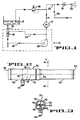
- the deicer pumping system of the present invention is shown incorporated into a fluid circuit for a typical aircraft deicer.
- a complete representation of the entire fluid circuit is not necessary to the understanding of the present invention.
- the pumping system described hereinafter can be incorporated into virtually any aircraft deicer comprising or connected to a fluid reservoir and requiring a primary pump to circulate the fluid through a heater and/or deliver the fluid under pressure to a nozzle for subsequent application to an aircraft requiring deicing, such as the deicer depicted and discussed in U.S. Patent No. 5,096,145, assigned to the assignee of this invention.
- deicer pumping system 10 is shown positioned in the deicer fluid circuit between a fluid reservoir 12 and a heater means 14.
- the fluid stored within reservoir 12 is typically water.
- Pumping system 10 draws water from reservoir 12 through a fluid conduit or section of pipe 16 at a particular rate, for example 100 gallons per minute. The water is then circulated by pumping system 10 through heater 14, wherein the water is heated to a desired temperature. As discussed above, this temperature is 200 degrees Fahrenheit or greater.
- a hand operated nozzle shut-off valve 18 controls the flow of the water through a nozzle 20.
- valve 18 When it is desired to apply a mixture of heated water and aircraft deicer fluid to an aircraft, valve 18 is opened and the water is directed into a fluid delivery conduit 22, where it is mixed by appropriate means with an aircraft deicer fluid supplied through a line 24 from a reservoir (not shown). The mixture is then ejected through nozzle 20 and onto the aircraft.
- valve 18 When valve 18 is closed, the water will circulate from heater 14 through a system relief valve 26 and back into reservoir 12. Consequently, the water contained within reservoir 12 is normally heated. The water will continue to circulate in this manner until valve 18 is again opened.
- deicer pumping system 10 comprises a primary pumping means 28, such as a centrifugal pump, and a jet pump means 30, which is connected in series with and upstream of pump 28.
- a primary pumping means 28 such as a centrifugal pump
- jet pump means 30 which is connected in series with and upstream of pump 28.
- Water from reservoir 12 enters jet pump 30 through pipe 16 and from there is directed through a length of conduit or pipe 32 to primary pump 28.
- a small portion of the water exiting primary pump 28, for example one fifth of the outflow, is directed through a section of conduit or pipe 34 back to jet pump 30, in a manner that will be described.
- jet pump 30 comprises a tubular body portion 36 having an inlet end 38, which is connected to pipe 16 by welding or any other appropriate means, and a discharge end 40, which is connected to pipe 32 in a similar fashion.
- the diameter of body portion 36 is approximately the same as the diameters of pipes 16 and 32.
- Jet pump 30 also comprises a nozzle means 42 inserted into body portion 36 between inlet 38 and discharge 40.
- Nozzle 42 is preferably constructed from a section of metal tubing, such as stainless steel, and comprises an inlet end 44, which is connected to pipe 34 by welding or any appropriate means, and an outlet 46.
- the diameter of nozzle 42 is preferably selected to be smaller than the diameter of pipe 34.
- nozzle 42 is bent approximately ninety degrees so that outlet 46 is aligned with the longitudinal axis of body portion 36.
- a number of fins 48 are positioned between nozzle 42 and the inside diameter of body portion 36. These fins can be welded to nozzle 42 to ensure their firm attachment thereto.
- body portion 36 is preferably constructed of three sections of pipe, 50, 52 and 54, which are welded together.
- the inside diameter of section 52 is slightly greater than the inside diameter of section 50 so that the velocity of the water flowing into jet pump 30 from pipe 16 will not decrease significantly upon encountering nozzle 42 in its path.
- semicircular holes are formed in the abutting ends of sections 50 and 52 to form an annular opening through which nozzle 42 extends when jet pump 30 is assembled.
- the inside diameter of section 54 is slightly smaller than the inside diameter of section 52 and consequently forms the diffuser portion of jet pump 30.
- primary pump 28 draws heated water at approximately atmospheric pressure from reservoir 12 at a preselected rate, such as the aforementioned 100 gallons per minute.
- the water is drawn through jet pump 30 and pipe 32 and into primary pump 28. From there the water is circulated through heater means 14 at the preselected rate and then either back into reservoir 12 or into conduit 22, depending on whether valve 18 is open or closed.
- a small portion of the pressurized water exiting primary pump 28, however, is pumped through pipe 34 back to jet pump 30, where it is introduced through nozzle 42 into the flow of water entering jet pump 30 from reservoir 12.
- the exact portion of water actually delivered through nozzle 42 depends on the diameters of pipe 34 and nozzle 42 and the pressure available from primary pump 28.
- the flow of pressurized water exiting nozzle 42 has a velocity much greater than the velocity of the water entering jet pump 30 through inlet 38.
- This jet of high velocity water creates a low pressure condition in the diffuser 54, which in turn serves to draw the water into inlet 38.
- the high velocity water discharging from nozzle 42 mixes with the lower velocity water entering jet pump 30 through inlet 38 to produce a combined flow of water having an intermediate velocity.
- the diffuser 54 functions in a known manner to convert the energy of this combined flow into a pressure at discharge end 40 of jet pump 30 which is greater than the pressure of the water prior to entering pumping system 10. This increased pressure is maintained in pipe 32 and is sufficiently greater than the vapor pressure of the water so as to prevent cavitation in primary pump 28.
Landscapes
- Engineering & Computer Science (AREA)
- Manufacturing & Machinery (AREA)
- Transportation (AREA)
- Aviation & Aerospace Engineering (AREA)
- Physics & Mathematics (AREA)
- Fluid Mechanics (AREA)
- Mechanical Engineering (AREA)
- General Engineering & Computer Science (AREA)
- Jet Pumps And Other Pumps (AREA)
Applications Claiming Priority (2)
| Application Number | Priority Date | Filing Date | Title |
|---|---|---|---|
| US08/005,317 US5454532A (en) | 1993-01-15 | 1993-01-15 | Aircraft deicer pumping system |
| US5317 | 1998-01-09 |
Publications (1)
| Publication Number | Publication Date |
|---|---|
| EP0606909A1 true EP0606909A1 (fr) | 1994-07-20 |
Family
ID=21715264
Family Applications (1)
| Application Number | Title | Priority Date | Filing Date |
|---|---|---|---|
| EP94100438A Withdrawn EP0606909A1 (fr) | 1993-01-15 | 1994-01-13 | Système de pompage pour le dégivrage d'avion |
Country Status (2)
| Country | Link |
|---|---|
| US (1) | US5454532A (fr) |
| EP (1) | EP0606909A1 (fr) |
Cited By (3)
| Publication number | Priority date | Publication date | Assignee | Title |
|---|---|---|---|---|
| WO1996017641A1 (fr) * | 1994-12-09 | 1996-06-13 | Cardiopulmonary Corporation | Respirateur |
| CN103244468A (zh) * | 2013-04-17 | 2013-08-14 | 武汉大学 | 引射式射流空化发生器及空化细胞破碎装置 |
| US9719232B2 (en) | 2011-12-22 | 2017-08-01 | Ihc Engineering Business Limited | Pump apparatus and underwater trenching apparatus |
Families Citing this family (12)
| Publication number | Priority date | Publication date | Assignee | Title |
|---|---|---|---|---|
| US6360992B1 (en) | 1996-06-28 | 2002-03-26 | Honeywell International Inc. | Hybrid deicing system and method of operation |
| US6047926A (en) | 1996-06-28 | 2000-04-11 | Alliedsignal Inc. | Hybrid deicing system and method of operation |
| US5996457A (en) * | 1997-07-15 | 1999-12-07 | Deltronic Labs Inc. | Apparatus for destruction of tickets and the like |
| US6766836B2 (en) | 2001-07-24 | 2004-07-27 | Edwards Electrical & Mechanical, Inc. | Glycol proportioning panel |
| CA2356066A1 (fr) | 2001-08-28 | 2003-02-28 | John M. Goston | Dispositifs pour le degivrage et l'antigivrage d'aeronefs |
| US20060272288A1 (en) * | 2005-06-03 | 2006-12-07 | Sealed Air Corporation (Us) | Small box shipper with internal inflatable bag |
| US7934680B2 (en) | 2007-05-21 | 2011-05-03 | Global Ground Support, Llc | Apparatus and method for blending fluids |
| US20110223039A1 (en) * | 2010-03-15 | 2011-09-15 | General Electric Company | Pump assembly and method |
| FR2959529B1 (fr) * | 2010-04-28 | 2014-04-18 | Snecma | Systeme carburant de turbomachine avec une pompe a jet pour pompe bp |
| US10737792B2 (en) * | 2016-09-22 | 2020-08-11 | The Boeing Company | Turbofan engine fluid ice protection delivery system |
| US11092126B2 (en) * | 2019-09-03 | 2021-08-17 | Pratt & Whitney Canada Corp. | Common-rail fuel system with ejector pump and method of use thereof |
| CN116658310B (zh) * | 2023-07-04 | 2026-05-01 | 中国航发沈阳发动机研究所 | 一种低功率提取的射流预冷控制系统 |
Citations (4)
| Publication number | Priority date | Publication date | Assignee | Title |
|---|---|---|---|---|
| US3730646A (en) * | 1971-05-04 | 1973-05-01 | A Affri | Fluid propelling system |
| US4037991A (en) * | 1973-07-26 | 1977-07-26 | The Plessey Company Limited | Fluid-flow assisting devices |
| WO1990009527A1 (fr) * | 1989-02-07 | 1990-08-23 | Stanley Joseph Lynch | Injecteur pneumatique pour substances liquides ou solides sous forme divisee |
| EP0441202A1 (fr) * | 1990-02-05 | 1991-08-14 | Fmc Corporation | Dispositif et méthode de dégivrage pour un avion |
Family Cites Families (15)
| Publication number | Priority date | Publication date | Assignee | Title |
|---|---|---|---|---|
| US2270911A (en) * | 1940-02-19 | 1942-01-27 | Charles W Linton | Kinetic pump |
| US3630051A (en) * | 1970-02-19 | 1971-12-28 | Graham Mfg Co Inc | Cold trap ice-removal means for vacuum drying systems |
| US3817659A (en) * | 1973-03-19 | 1974-06-18 | Kobe Inc | Pitot pump with jet pump charging system |
| US3946562A (en) * | 1974-11-07 | 1976-03-30 | Borg-Warner Corporation | Hydraulic system cavitation suppressor |
| US3987628A (en) * | 1976-03-04 | 1976-10-26 | Deere & Company | Charge pump augmenting device |
| GB1574829A (en) * | 1977-04-15 | 1980-09-10 | Rolls Royce | Jet pumps |
| SU631685A1 (ru) * | 1977-07-11 | 1978-11-05 | Московский Ордена Трудового Красного Знамени Геологоразведочный Институт Им. Серго Орджоникидзе | Эжектор |
| US4197712A (en) * | 1978-04-21 | 1980-04-15 | Brigham William D | Fluid pumping and heating system |
| US4294573A (en) * | 1979-05-17 | 1981-10-13 | Kobe, Inc. | Submersible electrically powered centrifugal and jet pump assembly |
| US4381175A (en) * | 1980-09-11 | 1983-04-26 | Kobe, Inc. | Jet electric pump |
| US4704070A (en) * | 1983-04-25 | 1987-11-03 | Iseman Walter J | Fuel system bubble dissipation device |
| DE3442716A1 (de) * | 1984-11-23 | 1986-05-28 | Wiederaufarbeitungsanlage Karlsruhe Betriebsgesellschaft mbH, 7514 Eggenstein-Leopoldshafen | Vorrichtung zum anfahren einer nicht selbstaendig ansaugenden kreiselpumpe |
| GB2208411B (en) * | 1987-06-25 | 1990-10-31 | Plessey Co Plc | Rotary pump system |
| US5190249A (en) * | 1989-09-25 | 1993-03-02 | Zwick Energy Research Organization, Inc. | Aircraft deicer fluid heating and propulsion system |
| US5242133A (en) * | 1990-12-28 | 1993-09-07 | Zwick Eugene B | Method and apparatus for heating and delivering deicing fluids |
-
1993
- 1993-01-15 US US08/005,317 patent/US5454532A/en not_active Expired - Fee Related
-
1994
- 1994-01-13 EP EP94100438A patent/EP0606909A1/fr not_active Withdrawn
Patent Citations (5)
| Publication number | Priority date | Publication date | Assignee | Title |
|---|---|---|---|---|
| US3730646A (en) * | 1971-05-04 | 1973-05-01 | A Affri | Fluid propelling system |
| US4037991A (en) * | 1973-07-26 | 1977-07-26 | The Plessey Company Limited | Fluid-flow assisting devices |
| WO1990009527A1 (fr) * | 1989-02-07 | 1990-08-23 | Stanley Joseph Lynch | Injecteur pneumatique pour substances liquides ou solides sous forme divisee |
| EP0441202A1 (fr) * | 1990-02-05 | 1991-08-14 | Fmc Corporation | Dispositif et méthode de dégivrage pour un avion |
| US5096145A (en) * | 1990-02-05 | 1992-03-17 | Fmc Corporation | Aircraft deicing apparatus and method |
Cited By (5)
| Publication number | Priority date | Publication date | Assignee | Title |
|---|---|---|---|---|
| WO1996017641A1 (fr) * | 1994-12-09 | 1996-06-13 | Cardiopulmonary Corporation | Respirateur |
| US5664563A (en) * | 1994-12-09 | 1997-09-09 | Cardiopulmonary Corporation | Pneumatic system |
| US9719232B2 (en) | 2011-12-22 | 2017-08-01 | Ihc Engineering Business Limited | Pump apparatus and underwater trenching apparatus |
| CN103244468A (zh) * | 2013-04-17 | 2013-08-14 | 武汉大学 | 引射式射流空化发生器及空化细胞破碎装置 |
| CN103244468B (zh) * | 2013-04-17 | 2015-11-04 | 武汉大学 | 引射式射流空化发生器及空化细胞破碎装置 |
Also Published As
| Publication number | Publication date |
|---|---|
| US5454532A (en) | 1995-10-03 |
Similar Documents
| Publication | Publication Date | Title |
|---|---|---|
| US5454532A (en) | Aircraft deicer pumping system | |
| US4846617A (en) | Jet pump, in particular for hot-water heating systems with return-flow mixing | |
| CA1280640C (fr) | Systeme variateur du rythme de debit pour un amplificateur hydrocinetique | |
| JP4718838B2 (ja) | 原動機或いは作業機械の流入路への液体噴射を制御する方法 | |
| US6595163B2 (en) | High pressure steam water injector comprising an axial drain | |
| US3720373A (en) | Recirculating paint system or the like | |
| WO1996027109A3 (fr) | Systeme de fourniture de bouillie de glace | |
| EP0849216A3 (fr) | Dispositif pour limiter la formation de mousse dans unrobinet de soutirage | |
| US20050077057A1 (en) | Fire truck booster pump | |
| US20110232774A1 (en) | Mixing eductor | |
| US4709515A (en) | Wet sandblasting system | |
| NO851923L (no) | Fremgangsmaate og innretning for fremstilling av med tilsatsmidler blandede slukkemidler. | |
| US3467314A (en) | Apparatus for cleaning objects | |
| US4583329A (en) | High pressure jets | |
| EP0294064B1 (fr) | Système de pompe centrifuge muni d'un réservoir d'entrée | |
| EP3878524A1 (fr) | Dispositif de production d'un mélange de gaz-liquide destiné à des fins de lutte contre l'incendie | |
| US20180111140A1 (en) | Spray proportioner system and hoses | |
| US2355882A (en) | Cleaning installation | |
| EP1106838A1 (fr) | Composant d'un système de chauffage | |
| GB2091911A (en) | Automatic control of liquid supply | |
| US4166477A (en) | Discharge conduits of steam generators and the like | |
| US2176682A (en) | Method and apparatus for washing | |
| US4714087A (en) | Fuel additive proportioning apparatus and method | |
| CN220424391U (zh) | 一种山地灭火系统 | |
| GB2225612A (en) | Improvements in liquid jet-producing apparatus |
Legal Events
| Date | Code | Title | Description |
|---|---|---|---|
| PUAI | Public reference made under article 153(3) epc to a published international application that has entered the european phase |
Free format text: ORIGINAL CODE: 0009012 |
|
| AK | Designated contracting states |
Kind code of ref document: A1 Designated state(s): AT BE CH DE FR GB LI LU NL SE |
|
| 17P | Request for examination filed |
Effective date: 19940628 |
|
| 17Q | First examination report despatched |
Effective date: 19950830 |
|
| GRAG | Despatch of communication of intention to grant |
Free format text: ORIGINAL CODE: EPIDOS AGRA |
|
| GRAH | Despatch of communication of intention to grant a patent |
Free format text: ORIGINAL CODE: EPIDOS IGRA |
|
| STAA | Information on the status of an ep patent application or granted ep patent |
Free format text: STATUS: THE APPLICATION HAS BEEN WITHDRAWN |
|
| 18W | Application withdrawn |
Withdrawal date: 19961121 |