EP0606941B1 - Einrichtung zur Synchronisierung eines lokalen Trägers, in OFDM-Systemen - Google Patents
Einrichtung zur Synchronisierung eines lokalen Trägers, in OFDM-Systemen Download PDFInfo
- Publication number
- EP0606941B1 EP0606941B1 EP94200027A EP94200027A EP0606941B1 EP 0606941 B1 EP0606941 B1 EP 0606941B1 EP 94200027 A EP94200027 A EP 94200027A EP 94200027 A EP94200027 A EP 94200027A EP 0606941 B1 EP0606941 B1 EP 0606941B1
- Authority
- EP
- European Patent Office
- Prior art keywords
- signal
- synchronization
- delay
- filter
- error
- Prior art date
- Legal status (The legal status is an assumption and is not a legal conclusion. Google has not performed a legal analysis and makes no representation as to the accuracy of the status listed.)
- Expired - Lifetime
Links
- 230000005540 biological transmission Effects 0.000 claims description 7
- 230000001934 delay Effects 0.000 claims description 4
- 230000003111 delayed effect Effects 0.000 claims description 4
- 238000001914 filtration Methods 0.000 claims description 2
- 230000003252 repetitive effect Effects 0.000 claims description 2
- 238000010586 diagram Methods 0.000 description 5
- 238000001228 spectrum Methods 0.000 description 3
- 230000006641 stabilisation Effects 0.000 description 3
- 238000011105 stabilization Methods 0.000 description 3
- 238000001514 detection method Methods 0.000 description 2
- 238000000034 method Methods 0.000 description 2
- 230000004913 activation Effects 0.000 description 1
- 239000000654 additive Substances 0.000 description 1
- 230000000996 additive effect Effects 0.000 description 1
- 238000013016 damping Methods 0.000 description 1
- 238000005562 fading Methods 0.000 description 1
- 238000005259 measurement Methods 0.000 description 1
- 238000005070 sampling Methods 0.000 description 1
Images

Classifications
-
- H—ELECTRICITY
- H03—ELECTRONIC CIRCUITRY
- H03L—AUTOMATIC CONTROL, STARTING, SYNCHRONISATION OR STABILISATION OF GENERATORS OF ELECTRONIC OSCILLATIONS OR PULSES
- H03L7/00—Automatic control of frequency or phase; Synchronisation
- H03L7/06—Automatic control of frequency or phase; Synchronisation using a reference signal applied to a frequency- or phase-locked loop
- H03L7/08—Details of the phase-locked loop
- H03L7/085—Details of the phase-locked loop concerning mainly the frequency- or phase-detection arrangement including the filtering or amplification of its output signal
- H03L7/095—Details of the phase-locked loop concerning mainly the frequency- or phase-detection arrangement including the filtering or amplification of its output signal using a lock detector
-
- H—ELECTRICITY
- H03—ELECTRONIC CIRCUITRY
- H03L—AUTOMATIC CONTROL, STARTING, SYNCHRONISATION OR STABILISATION OF GENERATORS OF ELECTRONIC OSCILLATIONS OR PULSES
- H03L7/00—Automatic control of frequency or phase; Synchronisation
- H03L7/06—Automatic control of frequency or phase; Synchronisation using a reference signal applied to a frequency- or phase-locked loop
- H03L7/08—Details of the phase-locked loop
- H03L7/10—Details of the phase-locked loop for assuring initial synchronisation or for broadening the capture range
- H03L7/107—Details of the phase-locked loop for assuring initial synchronisation or for broadening the capture range using a variable transfer function for the loop, e.g. low pass filter having a variable bandwidth
- H03L7/1075—Details of the phase-locked loop for assuring initial synchronisation or for broadening the capture range using a variable transfer function for the loop, e.g. low pass filter having a variable bandwidth by changing characteristics of the loop filter, e.g. changing the gain, changing the bandwidth
-
- H—ELECTRICITY
- H04—ELECTRIC COMMUNICATION TECHNIQUE
- H04L—TRANSMISSION OF DIGITAL INFORMATION, e.g. TELEGRAPHIC COMMUNICATION
- H04L27/00—Modulated-carrier systems
- H04L27/26—Systems using multi-frequency codes
- H04L27/2601—Multicarrier modulation systems
- H04L27/2647—Arrangements specific to the receiver only
- H04L27/2655—Synchronisation arrangements
- H04L27/2657—Carrier synchronisation
-
- H—ELECTRICITY
- H04—ELECTRIC COMMUNICATION TECHNIQUE
- H04L—TRANSMISSION OF DIGITAL INFORMATION, e.g. TELEGRAPHIC COMMUNICATION
- H04L27/00—Modulated-carrier systems
- H04L27/26—Systems using multi-frequency codes
- H04L27/2601—Multicarrier modulation systems
- H04L27/2647—Arrangements specific to the receiver only
- H04L27/2655—Synchronisation arrangements
- H04L27/2668—Details of algorithms
- H04L27/2673—Details of algorithms characterised by synchronisation parameters
- H04L27/2675—Pilot or known symbols
Definitions
- Such a synchronization device is for example described in the document JP. KOKAI - 60 16731. It describes a circuit formed by a phase-locked loop which determines an error signal characterizing a desynchronization, the error signal being able to be filtered either by a first filter or by a second filter having bands different bandwidths so that the error signal thus filtered gives rise to a control signal which acts on a local oscillator. The signal generated by this local oscillator is combined with the received signal to generate the error signal.
- the activation of one or the other filter depends on a discriminator circuit which detects the operating mode and selects the best filter appropriate in order to reduce FM noise and improve device performance.
- the discriminator circuit is fixed and is not self-adaptable to the acquisition / latching operating modes.
- a particular application of the device is in the reception of signals transmitted according to a multiplexed distribution of orthogonal frequencies (OFDM), transmitted in particular by hertzian way, by cable, by satellite, for example for applications in digital television.
- OFDM orthogonal frequencies
- phase detection does not work.
- the devices it is desirable that the devices not only be robust and precise but also that they have a low cost.
- the technique of transmitting signals according to a multiplexed distribution of N orthogonal frequencies consists in dividing information to be transmitted by distributing it over a large number of elementary channels at low bit rate 1 / T, T being the symbol duration.
- a highly selective broadband channel is thus transformed into a large number of elementary non-selective channels. Since the whole constitutes a broadband channel, it is unlikely that fading during transmission will affect the entire channel simultaneously. This technique also reduces intersymbol interference.
- Each elementary channel then corresponds to a frequency, the set of frequencies being symmetrically distributed around a carrier frequency.
- the set of frequencies being symmetrically distributed around a carrier frequency.
- the signals received must be demodulated and then decoded to restore the original information.
- This demodulation implements a local oscillator whose frequency must be slaved to the carrier frequency of the received signal.
- An object of the invention is thus to allow the carrier synchronization device to synchronize a locally generated carrier with a modulated signal received, the synchronization taking place with loop time constants adapted, in a self-programmable manner, to the operating modes. .
- a synchronization device in which, to deliver the selection signal, the servo mode detector calculates deviations between the control signal and at least one replica of said control signal delayed by programmable delay means which apply delays dedicated to each filter, comparison means comparing the deviations to at least a predetermined threshold to deliver the selection signal which determines the filter to be selected.
- said device reduces the frequency differences between the modulated signal received and the local carrier thanks to the use of a control signal u (t) (filtered error signal) which is proportional to the frequency. Switching from one filter to another is carried out by the device in a self-programming manner.
- the means which determine the desynchronization signal comprise either a frequency detector or a phase detector which measures the desynchronization by calculating the difference in frequency or phase respectively between the received signal and the local carrier.
- This device is particularly advantageous for enslaving the reception frequency of a receiver to the transmission frequency. For this, it is necessary to switch from an acquisition mode to an attachment mode and vice versa according to the transmission conditions operated by the transmission channel.
- the carrier synchronization device must switch from one mode to another.
- the delay means respectively either implement a first delay and select a first filter giving a wide loop band, or implement a second delay smaller than the first delay and select a second filter giving a narrow loop band.
- the device can be used for the synchronization of OFDM signals which are formatted in blocks of which at least one block is a repeating synchronization block.
- the frequency detector determines the error signal from this (these) repetitive synchronization block (s).
- the first and second delays can then be worth an integer number of times the transmission rate of the synchronization blocks.
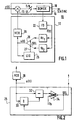
- Figure 1 a schematic representation of a receiver provided with a carrier synchronization device according to the invention.
- Figure 2 a diagram of an acquisition / attachment servo mode detector.
- Figure 3 a diagram of an exemplary embodiment of the programmable delay means.
- Figures 4 and 5 diagrams of low-pass filters for analog and digital embodiments.
- FIG. 1 schematically represents a receiver 10 comprising a demodulator 16 and a device 12 for synchronizing carrier frequency.
- the modulated signal r (t) received by the demodulator 16 is combined in a mixer 13 with a carrier generated locally by a local oscillator, for example an oscillator 20 controlled in VCO voltage.
- the outlet of the mixer 13 provides a baseband signal which enters a sampler 17 (T / N rate) and a demultiplexer 18 which delivers a sampled demodulated signal s (kT / N).
- T / N rate sampler 17
- demultiplexer 18 which delivers a sampled demodulated signal s (kT / N).
- the synchronization device 12 which operates in a loop. To do this, it receives data from the demultiplexer 18 from which desynchronization information is extracted which serves to control the frequency of the carrier generated by the local oscillator 20.
- Desynchronization is estimated, for example, using a frequency detector FD 22 which determines the frequency difference between r (t) and the frequency of the local oscillator and which generates an error signal ⁇ ( t).
- a frequency detector 22 for OFDM signals can be, for example, that described in application WO 92/16063.
- the error signal enters, in parallel, into two low-pass filters Hf 1 and Hf 2 , the outputs of which can be selected to deliver a control signal u (t).
- a LID 25 detector of the servo mode is used.
- the LID sensor 25 of the control mode operates this selection by acting on a selector 26.
- the detector 25 uses the control signal u (t) to deliver a selection signal SEL 27 which selects one or the other filter.
- FIG. 2 represents a diagram of the detector 25. It comprises programmable delay means 30, which apply a delay D, and a subtractor 32 which both receive the control signal u (t). The subtractor calculates deviations between the control signal u (t) and a replica of the same signal delayed by the means 30. The deviations are compared to a threshold Th in a comparator 34. The latter delivers a selection signal SEL which acts on the selector 26 placed at the outlet of the filters. The selector 26 can be placed before the filters. The selection signal SEL also acts on the delay means 30 to select each delay dedicated to each filter and make the device self-programmable.
- the delay D is set to a low value during the latching mode so that the synchronization device responds quickly at frequency changes. Similarly, the delay D is increased at the start of the acquisition period in order to reduce the problem of false hooking.
- the characteristics of the filters must be chosen in order to provide an acceptable acquisition time as well as an error variance ⁇ 2 as small as possible and a zero mean error under stable frequency conditions.
- An acceptable acquisition time is the result of a compromise between the shortest possible acquisition time and low jitter.
- the acquisition time Tacq can be defined as the time necessary to reduce the normalized frequency error to an average value less than 0.02.
- an Hf 1 filter which gives a second order loop having a normalized bandwidth B 1.
- T f 2 (T f being the duration between two synchronization blocks) and a factor d damping of 20.
- the frequency stabilization is estimated by the variance of ⁇ f.T S.
- the Hf 1 and Hf 2 filters can be produced in analog or digital. It is possible to put more than two filters.
- FIG. 3 represents a diagram of an exemplary embodiment of the delay means 30.
- They comprise a delay member 40 such as a shift register (in a digital embodiment) or a delay line (in an analog embodiment ).
- These delay means 30 are programmed to apply a delay value using a selector 42 which selects either a delay D1 or a delay D2. The selector is controlled by the selection signal SEL.
- the Th threshold value was set at 0.8.
- FIG. 4 represents an exemplary embodiment of analog filters.
- a gain amplifier -A receives the input signal ⁇ (t) through a resistor R.
- the input of the amplifier is joined at its output by a capacity C of feedback.
- the filtered signal u (t) appears, with respect to a mass G, at the output of the amplifier.
- the synchronization device 12 (figure 1) operates with the filter of figure 4-A, the loop is of first order. It becomes second order with a filter represented by the figure 4-B.
- the difference with the figure 4-A consists in placing a resistance R2 in series with the capacity C and to adjust the values of the elements R1 and C.
- Figures 5-A, 5-B are, numerically, filters equivalent to those of Figures 4-A and 4-B respectively.
- the signals are digital signals ⁇ k and u k .
- the signal ⁇ k is added, in an adder 50, to a signal formed by a delayed replica by the retarder 52 of the output signal from the adder 50.
- the output of the adder is also combined at the input of a multiplier 54 which multiplies the output signal of the summator by a weighting coefficient c to deliver the filtered signal u k .
- the 5-A filter is used to build a first order loop.
- the figure 5-B represents a filter allowing to build a loop of the second order. It also includes a summator 50, a retarder 52 and a multiplier 54 connected in the same way as in FIG. 5-A.
- the multiplier 54 receives a coefficient b.
- the input of the summator receives the signal ⁇ k which also enters a multiplier 56 (weighting coefficient a) the output of which is connected to a summator 58 which also receives the output of the multiplier 54.
- the output of the summator 58 delivers the filtered signal u k .
- an Hf 1 filter is used giving a second order loop and in the hooking mode, an Hf 2 filter is used giving a first order loop.
Landscapes
- Engineering & Computer Science (AREA)
- Computer Networks & Wireless Communication (AREA)
- Signal Processing (AREA)
- Synchronisation In Digital Transmission Systems (AREA)
- Digital Transmission Methods That Use Modulated Carrier Waves (AREA)
Claims (5)
- Eine Einrichtung (12) zur Synchronisierung eines Trägers für die Bewertung und den Ausgleich der Synchronisationsabweichungen zwischen einem lokalen Träger und einem für die Demodulation vom lokalen Träger erhaltenen modulierten Signal, das von der besagten Einrichtung erzeugt wurde und folgendes beinhaltet :- Mittel (22) zur Bestimmung eines Signalsfehlers ε(t) mit dem Merkmal einer Desynchronisation zwischen dem empfangenen Modulationssignal und dem lokalen Träger,- einen von einem Steuersignal [u(t)] gesteuerten lokalen Oszillator (20), der den lokalen Träger erzeugt,- mindestens zwei parallel zwischen die besagten Mittel (22) und den lokalen Oszillator angeschlossene Tiefpaßfilter (Hf1, Hf2), wobei diese beiden Filter das Fehlersignal filtern und unterschiedliche Schleifenfrequenzen liefern,- ein Regelmodusdetektor (25), der für die Auswahl einer der Filter ein Auswahlsignal (SEL) abgibt, wobei der Ausgang des ausgewählten Filters das besagte Steuersignal [u(t)] liefert,mit dem Merkmal, daß der Regelmodusdetektor (25) die Abweichungen zwischen dem Steuersignal [u(t)] und mindestens einem Duplikat des besagten Steuersignals berechnet, verzögert über programmierbare Verzögerungsmittel (30), die jedem Filter geeignete Verzögerungen zuweisen, während die Vergleichsmittel (34) die Abweichungen mit mindestens einer vorbestimmten Schwelle (Th) vergleichen, um das Auswahlsignal abzugeben, das den zu wählenden Filter bestimmt.
- Eine Einrichtung laut Anspruch 1, mit dem Merkmal, daß die besagten Mittel (22) entweder einen Frequenzdetektor oder einen Phasendetektor enthalten, der die Desynchronisation mißt, indem er den jeweiligen Frequenz- oder Phasenunterschied zwischen dem empfangenen Signal und dem lokalen Träger berechnet.
- Eine Einrichtung laut den Ansprüchen 1 oder 2, mit dem Merkmal, daß die Verzögerungsmittel (30), um die besagte Einrichtung entweder in Erfassungsmodus oder in Einschwingungsmodus arbeiten zu lassen, entweder eine erste Verzögerung bewirken und einen ersten Filter für den Erhalt einer breiten Schleife wählen, oder eine unter der ersten Verzögerung liegende zweite Verzögerung bewirken und einen zweiten Filter für den Erhalt einer engen Schleifenfrequenz wählen.
- Die Verwendung einer Einrichtung laut einem der Ansprüche 1 bis 3 zur Synchronisierung von OFDM-Signalen, in Blöcken formatiert, von denen mindestens ein Block ein Synchronisierungswiederholungsblock ist,
mit dem Merkmal, daß der Frequenzdetektor das Fehlersignal durch die Bewertung der Desynchronisation der empfangenen Synchronisationsblöcke bestimmt. - Die Verwendung laut Anspruch 4, mit dem Merkmal, daß die erste Verzögerung und die zweite Verzögerung den Wert einer Ganzzahl mal dem Übertragungstakt der Synchronisierungsblöcke aufweisen.
Applications Claiming Priority (2)
| Application Number | Priority Date | Filing Date | Title |
|---|---|---|---|
| FR9300245 | 1993-01-13 | ||
| FR9300245 | 1993-01-13 |
Publications (2)
| Publication Number | Publication Date |
|---|---|
| EP0606941A1 EP0606941A1 (de) | 1994-07-20 |
| EP0606941B1 true EP0606941B1 (de) | 1997-10-15 |
Family
ID=9442994
Family Applications (1)
| Application Number | Title | Priority Date | Filing Date |
|---|---|---|---|
| EP94200027A Expired - Lifetime EP0606941B1 (de) | 1993-01-13 | 1994-01-07 | Einrichtung zur Synchronisierung eines lokalen Trägers, in OFDM-Systemen |
Country Status (5)
| Country | Link |
|---|---|
| US (1) | US5541965A (de) |
| EP (1) | EP0606941B1 (de) |
| JP (1) | JP3429831B2 (de) |
| KR (1) | KR100337715B1 (de) |
| DE (1) | DE69406151T2 (de) |
Families Citing this family (22)
| Publication number | Priority date | Publication date | Assignee | Title |
|---|---|---|---|---|
| DE69502250T2 (de) * | 1994-08-25 | 1998-10-29 | Philips Electronics Nv | Digitales Übertragungssystem mit einer doppelten Synchronisierungsschleife |
| US6334219B1 (en) | 1994-09-26 | 2001-12-25 | Adc Telecommunications Inc. | Channel selection for a hybrid fiber coax network |
| USRE42236E1 (en) | 1995-02-06 | 2011-03-22 | Adc Telecommunications, Inc. | Multiuse subcarriers in multipoint-to-point communication using orthogonal frequency division multiplexing |
| US7280564B1 (en) | 1995-02-06 | 2007-10-09 | Adc Telecommunications, Inc. | Synchronization techniques in multipoint-to-point communication using orthgonal frequency division multiplexing |
| EP0748093A1 (de) * | 1995-06-08 | 1996-12-11 | Laboratoires D'electronique Philips S.A.S. | Digitales Übertragungssystem mit Entscheidungsmitteln zur Auswahl der Synchronisierungsart |
| US5828705A (en) * | 1996-02-01 | 1998-10-27 | Kroeger; Brian W. | Carrier tracking technique and apparatus having automatic flywheel/tracking/reacquisition control and extended signal to noise ratio |
| US6055231A (en) * | 1997-03-12 | 2000-04-25 | Interdigital Technology Corporation | Continuously adjusted-bandwidth discrete-time phase-locked loop |
| JP3466422B2 (ja) | 1997-05-28 | 2003-11-10 | 株式会社ケンウッド | 受信装置 |
| US6359878B1 (en) | 1998-07-20 | 2002-03-19 | Wirless Facilities, Inc. | Non-data-aided maximum likelihood based feedforward timing synchronization method |
| US6654432B1 (en) | 1998-06-08 | 2003-11-25 | Wireless Facilities, Inc. | Joint maximum likelihood frame and timing estimation for a digital receiver |
| KR100378058B1 (ko) * | 1998-09-28 | 2003-03-29 | 마쯔시다덴기산교 가부시키가이샤 | Vsb수신기 |
| US6430235B1 (en) | 1998-11-05 | 2002-08-06 | Wireless Facilities, Inc. | Non-data-aided feedforward timing synchronization method |
| US6738429B1 (en) | 1999-06-01 | 2004-05-18 | Harris Corporation | Decision-directed carrier frequency detector and method for QAM |
| KR100529150B1 (ko) * | 1999-06-24 | 2005-11-16 | 매그나칩 반도체 유한회사 | 주파수 옵셋 및 위상 에러를 동시에 줄이는 반송파 주파수 복구 방법 및 장치 |
| US6505037B1 (en) * | 1999-06-29 | 2003-01-07 | Sharp Laboratories Of America, Inc. | Data unit detection including antenna diversity |
| US6859504B1 (en) | 1999-06-29 | 2005-02-22 | Sharp Laboratories Of America, Inc. | Rapid settling automatic gain control with minimal signal distortion |
| DE19933535A1 (de) * | 1999-07-16 | 2001-01-25 | Polytrax Inf Technology Ag | Synchronisationsverfahren zur Datenübertragung |
| US6606357B1 (en) | 1999-09-10 | 2003-08-12 | Harris Corporation | Carrier injecting waveform-based modulation scheme for reducing satellite transponder power requirements and earth terminal antenna size |
| US6683920B1 (en) | 2000-09-22 | 2004-01-27 | Applied Micro Circuits Corporation | Dual-loop system and method for frequency acquisition and tracking |
| US6704329B2 (en) * | 2001-05-08 | 2004-03-09 | Path 1 Network Technologies Inc. | Minimizing the effect of jitter upon the quality of service operation of networked gateway devices |
| JP3798656B2 (ja) * | 2001-06-22 | 2006-07-19 | 株式会社ケンウッド | 直交周波数分割多重信号受信装置、受信装置、直交周波数分割多重信号受信方法及び受信方法 |
| DE102005000053A1 (de) * | 2005-05-10 | 2006-11-16 | Hilti Ag | Handgeführten, scannender Untergrunddetektor |
Family Cites Families (13)
| Publication number | Priority date | Publication date | Assignee | Title |
|---|---|---|---|---|
| US3909735A (en) * | 1974-04-04 | 1975-09-30 | Ncr Co | Slow switch for bandwidth change in phase-locked loop |
| US4215239A (en) * | 1977-12-05 | 1980-07-29 | E-Systems, Inc. | Apparatus for the acquisition of a carrier frequency and symbol timing lock |
| US4473805A (en) * | 1981-12-14 | 1984-09-25 | Rca Corporation | Phase lock loss detector |
| US4718116A (en) * | 1982-06-01 | 1988-01-05 | Aerotron, Inc. | Method and apparatus for receiving a compressed composite signal |
| US4573208A (en) * | 1982-06-01 | 1986-02-25 | Aerotron, Inc. | Compressed single side band communications system and method |
| US4539707A (en) * | 1982-06-01 | 1985-09-03 | Aerotron, Inc. | Compressed single side band communications system and method |
| JPS6016731A (ja) * | 1984-06-21 | 1985-01-28 | Matsushita Electric Ind Co Ltd | Pll回路装置 |
| US4855689A (en) * | 1987-02-13 | 1989-08-08 | Hughes Aircraft Company | Phase lock loop with switchable filter for acquisition and tracking modes |
| US4724401A (en) * | 1987-04-23 | 1988-02-09 | Rockwell International Corporation | Adaptive oscillator apparatus for use in a phase-lock loop |
| US5065107A (en) * | 1990-04-19 | 1991-11-12 | University Of Saskatchewan | Phase-locked loop bandwidth switching demodulator for suppressed carrier signals |
| FR2670062B1 (fr) * | 1990-11-30 | 1993-11-12 | Thomson Csf | Procede de recalage des oscillateurs locaux d'un recepteur et dispositif pour la mise en óoeuvre du procede. |
| SG44771A1 (en) * | 1991-02-28 | 1997-12-19 | Philips Electronics Nv | System for broadcasting and receiving digital data receiver and transmitter for use in such system |
| US5425057A (en) * | 1994-04-25 | 1995-06-13 | Paff; Thomas M. | Phase demodulation method and apparatus using asynchronous sampling pulses |
-
1994
- 1994-01-07 EP EP94200027A patent/EP0606941B1/de not_active Expired - Lifetime
- 1994-01-07 DE DE69406151T patent/DE69406151T2/de not_active Expired - Fee Related
- 1994-01-12 KR KR1019940000390A patent/KR100337715B1/ko not_active Expired - Fee Related
- 1994-01-12 US US08/181,262 patent/US5541965A/en not_active Expired - Lifetime
- 1994-01-13 JP JP00207394A patent/JP3429831B2/ja not_active Expired - Fee Related
Also Published As
| Publication number | Publication date |
|---|---|
| KR100337715B1 (ko) | 2002-08-21 |
| JPH06244813A (ja) | 1994-09-02 |
| US5541965A (en) | 1996-07-30 |
| JP3429831B2 (ja) | 2003-07-28 |
| EP0606941A1 (de) | 1994-07-20 |
| DE69406151T2 (de) | 1998-04-02 |
| DE69406151D1 (de) | 1997-11-20 |
Similar Documents
| Publication | Publication Date | Title |
|---|---|---|
| EP0606941A1 (de) | Einrichtung zur Synchronisierung eines lokalen Trägers, in OFDM-Systemen | |
| EP0580216B1 (de) | Anordnung und Empfänger von orthogonalen Frequenzmultiplexsignalen mit einer Frequenzsynchronisationsschaltung | |
| EP0674412B1 (de) | Verfahren und Vorrichtung für automatische Frequenzregelung | |
| EP0559883B1 (de) | Digitale uebertragungsanordnung und direktkonvertierungsempfänger | |
| EP0513313B1 (de) | Verfahren zur neusynchronisierung der lokalen oszillatoren eines empfängers und vorrichtung zur durchführung des verfahrens | |
| EP0709980B1 (de) | Frequenzsynchronisierung für OFDM-System | |
| EP0608024B1 (de) | Übertragungssystem mit Taktrückgewinnung | |
| FR2478914A1 (fr) | Procede et dispositif pour l'ajustement initial de l'horloge d'un recepteur de donnees synchrone | |
| FR2601212A1 (fr) | Modem prevu pour l'utilisation dans des systemes de telecommunication comportant des chemins multiples | |
| FR2533095A1 (fr) | Procede et dispositif de demodulation d'une onde porteuse modulee en phase par une onde sous-porteuse qui est modulee en deplacement de phase par des signaux en bande de base | |
| FR2667750A1 (fr) | Reseau cable et dispositif modulateur-demodulateur pour un tel reseau. | |
| FR2470480A1 (de) | ||
| FR2770700A1 (fr) | Dispositif et procede pour synchroniser des oscillateurs dans un systeme de communication de donnees | |
| FR2508751A1 (fr) | Recepteur-son d'un televiseur | |
| EP0012884A1 (de) | Verfahren und Vorrichtung zur Auffindung einer Pseudo-Zufallsfolge zweier Symbole in einem Datenempfänger, welcher eine Doppelzeitenbandmodulation mit Quadraturträgern verwendet | |
| JP2848328B2 (ja) | 位相変調信号復調方法およびその方法を実施するための装置 | |
| EP0140753B1 (de) | Verfahren und Vorrichtung zur kohärenten Demodulation eines digital modulierten Trägers | |
| EP0705513B1 (de) | Mpsk-demodulator | |
| CA2078780C (fr) | Procede de demodulation coherente pour modulation a deplacement de phase et dispositif de mise en oeuvre de ce procede | |
| EP0715434A1 (de) | Detektionsgerät zum Erkennung eines digital modulierten Trägers | |
| EP1742375A1 (de) | Korrektur von Fehlern bei der Anpassung von zwei I und Q Pfaden | |
| FR2688962A1 (fr) | Procede pour la transmission de signaux numeriques a large bande d'une station fixe a une station mobile. | |
| EP0494003B1 (de) | Empfangsanordnung zur Verarbeitung von auf verschiedenen Wegen empfangenen Signalen | |
| FR2659508A1 (fr) | Demodulateur de frequences a abaissement de seuil. | |
| EP0790729A1 (de) | Korrektur von Phasenrauschen eines PLL in einem PSK- oder QAM-Empfänger |
Legal Events
| Date | Code | Title | Description |
|---|---|---|---|
| PUAI | Public reference made under article 153(3) epc to a published international application that has entered the european phase |
Free format text: ORIGINAL CODE: 0009012 |
|
| AK | Designated contracting states |
Kind code of ref document: A1 Designated state(s): DE FR GB IT |
|
| RAP1 | Party data changed (applicant data changed or rights of an application transferred) |
Owner name: N.V. PHILIPS' GLOEILAMPENFABRIEKEN Owner name: LABORATOIRES D'ELECTRONIQUE PHILIPS |
|
| 17P | Request for examination filed |
Effective date: 19950120 |
|
| RAP1 | Party data changed (applicant data changed or rights of an application transferred) |
Owner name: PHILIPS ELECTRONICS N.V. Owner name: LABORATOIRES D'ELECTRONIQUE PHILIPS S.A.S. |
|
| GRAG | Despatch of communication of intention to grant |
Free format text: ORIGINAL CODE: EPIDOS AGRA |
|
| 17Q | First examination report despatched |
Effective date: 19961230 |
|
| GRAH | Despatch of communication of intention to grant a patent |
Free format text: ORIGINAL CODE: EPIDOS IGRA |
|
| GRAH | Despatch of communication of intention to grant a patent |
Free format text: ORIGINAL CODE: EPIDOS IGRA |
|
| GRAA | (expected) grant |
Free format text: ORIGINAL CODE: 0009210 |
|
| AK | Designated contracting states |
Kind code of ref document: B1 Designated state(s): DE FR GB IT |
|
| REF | Corresponds to: |
Ref document number: 69406151 Country of ref document: DE Date of ref document: 19971120 |
|
| GBT | Gb: translation of ep patent filed (gb section 77(6)(a)/1977) |
Effective date: 19971106 |
|
| ITF | It: translation for a ep patent filed | ||
| PLBE | No opposition filed within time limit |
Free format text: ORIGINAL CODE: 0009261 |
|
| STAA | Information on the status of an ep patent application or granted ep patent |
Free format text: STATUS: NO OPPOSITION FILED WITHIN TIME LIMIT |
|
| RAP4 | Party data changed (patent owner data changed or rights of a patent transferred) |
Owner name: KONINKLIJKE PHILIPS ELECTRONICS N.V. Owner name: LABORATOIRES D'ELECTRONIQUE PHILIPS S.A.S. |
|
| 26N | No opposition filed | ||
| REG | Reference to a national code |
Ref country code: FR Ref legal event code: TP |
|
| REG | Reference to a national code |
Ref country code: GB Ref legal event code: IF02 |
|
| REG | Reference to a national code |
Ref country code: GB Ref legal event code: 746 Effective date: 20020923 |
|
| REG | Reference to a national code |
Ref country code: FR Ref legal event code: D6 |
|
| PGFP | Annual fee paid to national office [announced via postgrant information from national office to epo] |
Ref country code: FR Payment date: 20040128 Year of fee payment: 11 |
|
| PGFP | Annual fee paid to national office [announced via postgrant information from national office to epo] |
Ref country code: GB Payment date: 20040129 Year of fee payment: 11 |
|
| PGFP | Annual fee paid to national office [announced via postgrant information from national office to epo] |
Ref country code: DE Payment date: 20040316 Year of fee payment: 11 |
|
| PG25 | Lapsed in a contracting state [announced via postgrant information from national office to epo] |
Ref country code: IT Free format text: LAPSE BECAUSE OF NON-PAYMENT OF DUE FEES;WARNING: LAPSES OF ITALIAN PATENTS WITH EFFECTIVE DATE BEFORE 2007 MAY HAVE OCCURRED AT ANY TIME BEFORE 2007. THE CORRECT EFFECTIVE DATE MAY BE DIFFERENT FROM THE ONE RECORDED. Effective date: 20050107 Ref country code: GB Free format text: LAPSE BECAUSE OF NON-PAYMENT OF DUE FEES Effective date: 20050107 |
|
| PG25 | Lapsed in a contracting state [announced via postgrant information from national office to epo] |
Ref country code: DE Free format text: LAPSE BECAUSE OF NON-PAYMENT OF DUE FEES Effective date: 20050802 |
|
| GBPC | Gb: european patent ceased through non-payment of renewal fee |
Effective date: 20050107 |
|
| PG25 | Lapsed in a contracting state [announced via postgrant information from national office to epo] |
Ref country code: FR Free format text: LAPSE BECAUSE OF NON-PAYMENT OF DUE FEES Effective date: 20050930 |
|
| REG | Reference to a national code |
Ref country code: FR Ref legal event code: ST |