EP0606982B1 - Une imprimante électrophotographique en couleur et un procédé d'impression utilisant une telle imprimante - Google Patents
Une imprimante électrophotographique en couleur et un procédé d'impression utilisant une telle imprimante Download PDFInfo
- Publication number
- EP0606982B1 EP0606982B1 EP94300069A EP94300069A EP0606982B1 EP 0606982 B1 EP0606982 B1 EP 0606982B1 EP 94300069 A EP94300069 A EP 94300069A EP 94300069 A EP94300069 A EP 94300069A EP 0606982 B1 EP0606982 B1 EP 0606982B1
- Authority
- EP
- European Patent Office
- Prior art keywords
- color
- toner material
- photosensitive body
- pixel elements
- toner
- Prior art date
- Legal status (The legal status is an assumption and is not a legal conclusion. Google has not performed a legal analysis and makes no representation as to the accuracy of the status listed.)
- Expired - Lifetime
Links
Images



Classifications
-
- G—PHYSICS
- G03—PHOTOGRAPHY; CINEMATOGRAPHY; ANALOGOUS TECHNIQUES USING WAVES OTHER THAN OPTICAL WAVES; ELECTROGRAPHY; HOLOGRAPHY
- G03G—ELECTROGRAPHY; ELECTROPHOTOGRAPHY; MAGNETOGRAPHY
- G03G15/00—Apparatus for electrographic processes using a charge pattern
- G03G15/01—Apparatus for electrographic processes using a charge pattern for producing multicoloured copies
- G03G15/0105—Details of unit
- G03G15/0121—Details of unit for developing
-
- G—PHYSICS
- G03—PHOTOGRAPHY; CINEMATOGRAPHY; ANALOGOUS TECHNIQUES USING WAVES OTHER THAN OPTICAL WAVES; ELECTROGRAPHY; HOLOGRAPHY
- G03G—ELECTROGRAPHY; ELECTROPHOTOGRAPHY; MAGNETOGRAPHY
- G03G13/00—Electrographic processes using a charge pattern
- G03G13/01—Electrographic processes using a charge pattern for multicoloured copies
-
- G—PHYSICS
- G03—PHOTOGRAPHY; CINEMATOGRAPHY; ANALOGOUS TECHNIQUES USING WAVES OTHER THAN OPTICAL WAVES; ELECTROGRAPHY; HOLOGRAPHY
- G03G—ELECTROGRAPHY; ELECTROPHOTOGRAPHY; MAGNETOGRAPHY
- G03G15/00—Apparatus for electrographic processes using a charge pattern
- G03G15/04—Apparatus for electrographic processes using a charge pattern for exposing, i.e. imagewise exposure by optically projecting the original image on a photoconductive recording material
- G03G15/04036—Details of illuminating systems, e.g. lamps, reflectors
- G03G15/04045—Details of illuminating systems, e.g. lamps, reflectors for exposing image information provided otherwise than by directly projecting the original image onto the photoconductive recording material, e.g. digital copiers
- G03G15/04072—Details of illuminating systems, e.g. lamps, reflectors for exposing image information provided otherwise than by directly projecting the original image onto the photoconductive recording material, e.g. digital copiers by laser
-
- H—ELECTRICITY
- H04—ELECTRIC COMMUNICATION TECHNIQUE
- H04N—PICTORIAL COMMUNICATION, e.g. TELEVISION
- H04N1/00—Scanning, transmission or reproduction of documents or the like, e.g. facsimile transmission; Details thereof
- H04N1/46—Colour picture communication systems
- H04N1/50—Picture reproducers
- H04N1/506—Reproducing the colour component signals picture-sequentially, e.g. with reproducing heads spaced apart from one another in the subscanning direction
- H04N1/508—Reproducing the colour component signals picture-sequentially, e.g. with reproducing heads spaced apart from one another in the subscanning direction using the same reproducing head for two or more colour components
-
- G—PHYSICS
- G03—PHOTOGRAPHY; CINEMATOGRAPHY; ANALOGOUS TECHNIQUES USING WAVES OTHER THAN OPTICAL WAVES; ELECTROGRAPHY; HOLOGRAPHY
- G03G—ELECTROGRAPHY; ELECTROPHOTOGRAPHY; MAGNETOGRAPHY
- G03G2215/00—Apparatus for electrophotographic processes
- G03G2215/00362—Apparatus for electrophotographic processes relating to the copy medium handling
- G03G2215/00443—Copy medium
- G03G2215/00451—Paper
- G03G2215/00455—Continuous web, i.e. roll
-
- G—PHYSICS
- G03—PHOTOGRAPHY; CINEMATOGRAPHY; ANALOGOUS TECHNIQUES USING WAVES OTHER THAN OPTICAL WAVES; ELECTROGRAPHY; HOLOGRAPHY
- G03G—ELECTROGRAPHY; ELECTROPHOTOGRAPHY; MAGNETOGRAPHY
- G03G2215/00—Apparatus for electrophotographic processes
- G03G2215/00362—Apparatus for electrophotographic processes relating to the copy medium handling
- G03G2215/00443—Copy medium
- G03G2215/00493—Plastic
- G03G2215/00497—Overhead Transparency, i.e. OHP
-
- G—PHYSICS
- G03—PHOTOGRAPHY; CINEMATOGRAPHY; ANALOGOUS TECHNIQUES USING WAVES OTHER THAN OPTICAL WAVES; ELECTROGRAPHY; HOLOGRAPHY
- G03G—ELECTROGRAPHY; ELECTROPHOTOGRAPHY; MAGNETOGRAPHY
- G03G2215/00—Apparatus for electrophotographic processes
- G03G2215/01—Apparatus for electrophotographic processes for producing multicoloured copies
- G03G2215/0103—Plural electrographic recording members
- G03G2215/0106—At least one recording member having plural associated developing units
-
- G—PHYSICS
- G03—PHOTOGRAPHY; CINEMATOGRAPHY; ANALOGOUS TECHNIQUES USING WAVES OTHER THAN OPTICAL WAVES; ELECTROGRAPHY; HOLOGRAPHY
- G03G—ELECTROGRAPHY; ELECTROPHOTOGRAPHY; MAGNETOGRAPHY
- G03G2215/00—Apparatus for electrophotographic processes
- G03G2215/01—Apparatus for electrophotographic processes for producing multicoloured copies
- G03G2215/0167—Apparatus for electrophotographic processes for producing multicoloured copies single electrographic recording member
- G03G2215/017—Apparatus for electrophotographic processes for producing multicoloured copies single electrographic recording member single rotation of recording member to produce multicoloured copy
-
- G—PHYSICS
- G03—PHOTOGRAPHY; CINEMATOGRAPHY; ANALOGOUS TECHNIQUES USING WAVES OTHER THAN OPTICAL WAVES; ELECTROGRAPHY; HOLOGRAPHY
- G03G—ELECTROGRAPHY; ELECTROPHOTOGRAPHY; MAGNETOGRAPHY
- G03G2215/00—Apparatus for electrophotographic processes
- G03G2215/01—Apparatus for electrophotographic processes for producing multicoloured copies
- G03G2215/0167—Apparatus for electrophotographic processes for producing multicoloured copies single electrographic recording member
- G03G2215/0187—Multicoloured toner image formed on the recording member
-
- G—PHYSICS
- G03—PHOTOGRAPHY; CINEMATOGRAPHY; ANALOGOUS TECHNIQUES USING WAVES OTHER THAN OPTICAL WAVES; ELECTROGRAPHY; HOLOGRAPHY
- G03G—ELECTROGRAPHY; ELECTROPHOTOGRAPHY; MAGNETOGRAPHY
- G03G2215/00—Apparatus for electrophotographic processes
- G03G2215/04—Arrangements for exposing and producing an image
- G03G2215/0402—Exposure devices
- G03G2215/0404—Laser
-
- G—PHYSICS
- G03—PHOTOGRAPHY; CINEMATOGRAPHY; ANALOGOUS TECHNIQUES USING WAVES OTHER THAN OPTICAL WAVES; ELECTROGRAPHY; HOLOGRAPHY
- G03G—ELECTROGRAPHY; ELECTROPHOTOGRAPHY; MAGNETOGRAPHY
- G03G2215/00—Apparatus for electrophotographic processes
- G03G2215/04—Arrangements for exposing and producing an image
- G03G2215/0495—Plural charge levels of latent image produced, e.g. trilevel
Definitions
- the present invention relates to an electrophotographic color printer. It is particularly, but not exclusively, concerned with an electrophotographic color printer capable of achieving full-color images.
- the present invention also relates to a method of printing using such a printer.
- a latent image is formed on a photosensitive body, by exposing that photosensitive body to a suitably modulated light beam, and then toner material of the color to be printed is applied to the photosensitive body, such that the pattern formed by the toner material corresponds to the latent image on the photosensitive body.
- This transferring step is also referred as developing the latent image.
- the toner material on the photosensitive body is transferred to a recording medium (for example, a sheet of paper), and is fixed thereto by a suitable fixing process (for example, heating the toner material to cause it to fuse).
- magenta M and yellow Y together produce red R
- yellow Y and cyan C produce green G
- cyan C and magenta M produce blue B.
- the full-color image was produced by repeating for each color the steps that are carried out in single-color printing.
- the steps of exposing the photosensitive body, applying colored toner material to the photosensitive body and transferring the toner material image to a recording medium had to be carried out sequentially.
- Such printing was slow, and also required precise alignment of the recording medium when the toner materials were each transferred, to ensure correct superposition of the primary color toner materials when it was desired to produce secondary colors.
- the resulting thickness of the toner material may be varied.
- the degree of saturation of color will vary only up to a predetermined thickness, with thicknesses above that predetermined level having no effect on color saturation. Therefore, in order to avoid waste of toner material, it is normal to apply the toner material to the photosensitive body to a thickness that will achieve saturation when the toner material is transferred to the recording medium and fixed. Therefore, in all of the known techniques discussed above, the thickness of the toner material is substantially uniform for all colors.
- toner material is applied to the photosensitive body, and hence transferred to the recording medium, in a multiplicity of dots known as pixels or pixel elements.
- pixels or pixel elements When the toner material is fixed, there is some spreading of the toner material, as it partially liquifies, and thus the size of the pixels increases slightly. Normally, therefore, small gaps have been left between the pixels when the toner material or materials are first transferred to the photosensitive body. The increase in size of the pixels depends on the amount of toner.
- the present invention derives from the realization that these two effects may be combined in multi-color printing.
- an electrophotographic color printer comprising:
- a method of electrophotographic color printing comprising:
- the first aspect of the present invention enables pixel elements of two different colors to be formed, and also regions corresponding to the mixture of those two colors to be achieved. This is not possible in US Patent Specification No. 4,078,929 discussed above, since the two colors are necessarily separate in that disclosure. Nor is it possible in US Patent Specification No. 4,731,634 discussed above, where it is possible only to produce separate colors, or mixtures of one of those colors with a third color.
- the different thicknesses of the toner materials can be achieved by suitable variation in the voltage levels produced by the exposure of the photosensitive body.
- the pixel elements are of two different sizes.
- the pixel elements which are to have thicker toner material are smaller (for example, half the width) where the toner material is to have a smaller thickness.
- the toner material of adjacent pixel elements mixes, it will appreciated that the resulting toner region will be approximately double the original width of the pixel element, and therefore it is convenient if the pixel elements of smaller toner thickness have the same width ad this double width region. In this way, regions of approximately the same width are obtained for each color.
- the first aspect of the invention results in the mixing of toner materials of two different colors at selected adjacent pixels, to produce a third color.
- the two further colors of toner material may be applied to a recording medium in a separate transfer step.
- the arrangement of a first aspect of the present invention is carried out, and the toner material is transferred to a suitable recording medium (e.g. paper).
- a further photosensitive body is exposed to form another exposure pattern thereon and the two additional colors of toner materials are transferred thereto, using, e.g. the techniques disclosed in US Patent Specification No. 4,078,929.
- such toner materials may be transferred to the recording medium.
- the toner materials applied to the first photosensitive body are cyan C and magenta M.
- blue B regions can be produced by forming adjacent pixels of cyan and magenta toner material which are sufficiently thick that they will mix during fixing.
- the second photosensitive body then receives yellow Y and black K toner materials. If some of the yellow toner material is transferred to the recording medium so as to overlie the pixels of cyan toner material, then the color green G will be produced when the toner materials are fixed. Similarly, if yellow toner material overlies the pixels of magenta toner material, then the color red R will be produced. Where no toner material is transferred to the recording medium, the background color (white in the case of paper), will be produced. Hence, the full range of colors may be achieved.
- the above arrangements makes use of two photosensitive bodies. It is also possible to make use of the present invention in arrangements in which there is only one photosensitive body. In this case, however, the recording medium must pass the photosensitive body twice. Thus, the first exposure of the photosensitive bodies carried out, and toner materials of first and second colors applied thereto.
- a third color can be achieved by providing adjacent pixels of the first and second toner materials with a thickness sufficient that they will mix when the toner materials are fused. Then, the photosensitive body is cleared of toner material, re-exposed, and toner materials of third and fourth colors applied thereto, and subsequently transferred to the recording medium. The effect is then similar to the use of two photosensitive bodies.
- the two toner materials of the first latent image must be transferred prior to the formation of the second latent image.
- simultaneous transfer of all the toner materials can be achieved, thereby reducing the risk of misalignment of the colors.
- the present invention makes use of voltage levels generated on the photosensitive body by suitable exposure.
- the exposure pattern is formed on the photosensitive body which has at least five voltage levels.
- a background voltage level there is a first voltage level positive relative to the background, a second voltage level positive relative to both the first and the background, a third voltage level negative to the background, and a fourth voltage level negative relative to both the third and background levels.
- Toner material of the first color is then applied to the regions corresponding to the first and second voltage levels, and second toner material is applied to the regions with the third and fourth voltage levels.
- the first and second voltage levels have the opposite polarity to the third and fourth voltage levels, relative to the background voltage level, the pixels of each toner material will be independent.
- the pixel regions corresponding to the second and fourth voltage levels will receive more toner material than the pixels corresponding to the first and third voltage levels, so that they can receive sufficient toner material to mix with adjacent pixels when the toner materials are fixed.
- a third color can be achieved by mixing of the first and second toner materials.
- This may be developed further, by using fifth and sixth voltage levels, being respectively more positive, and more negative than the second and fourth voltage levels.
- the first toner material, and a third toner material may then be transferred to the regions corresponding to the fifth voltage level, and the second toner material and the third toner material may then be transferred to the regions corresponding to the sixth voltage level by providing both positively and negatively charged toner material of the third color.
- additional colors can be generated using a single exposure of the photosensitive body. Although this single exposure cannot result in a full-color process, because the pixels of the third color cannot be produced independently, printing can occur at high speed, because there is only one exposure needed, and the range of colors thus produced at such speeds is greater than can be achieved by known methods. Of course, by using an additional exposure step, this can be developed into full-color printing.
- the electrophotographic color printer Many different arrangements of the electrophotographic color printer are possible, based on the discussion above, involving one or two photosensitive bodies, one or two exposure means for exposing the photosensitive body or bodies, and an appropriate plurality of developer means which apply the different toner materials. Where a plurality of photosensitive bodies are used, the recording medium passes each photosensitive body once in the production of the final image. Where there is only one photosensitive body, it may be necessary to cause the recording medium to pass that photosensitive body more than once.
- a known method of making a full-color image involves superimposing and developing one color at a time.
- the component colors are mixed, as shown in Fig. 1(b), to generate a third color.
- each area corresponding to one ordinary picture element or dot is divided into halves.
- a first color toner e.g. cyan
- the remaining half area receives the same amount of a second toner (e.g. magenta).
- Such color mixing occurs as follows. As shown in Fig. 1(a), when an electrostatic latent image is formed on the surface of a photosensitive body, the image exposure is controlled so that the potentials of the color mixing areas are set more positive (at -100 V) or more negative (at -900 V) than those potentials of areas where single colors are produced (-200 V and -800 V), with the potential (-500 V) of white areas taken as a background voltage.
- the exposure causes the surface of the photosensitive body to have two positive potential levels and two negative potential levels relative to the potential of the background voltage (white areas) where no toner is to be attached.
- Fig. 2 shows a schematic configuration of a printing system according to this invention.
- a full-color printer structure 200 receives image signals 400 representing each dot of an image from a host computer 100.
- the image signal 400 may take various forms according to the type of equipment.
- the image signal has a total of three bits, one for each color.
- the image signal for each dot includes information representing one of eight colors, including red R, green G, blue B, cyan C, magenta M, yellow Y, and white W. Other colors are produced by a known artificial intermediate hue generation technique employed in the host computer 200.
- Data sent to the full-color printer structure 200 enters a printer control unit 210, which generates control signals that control a printer unit 250.
- Fig. 3 shows the overall configuration of a first embodiment of the printer unit 250 according to the present invention, for use in the full-color printer structure 200.
- the recording medium can be, for example, paper sheets, continuous paper, or OHP transparencies. In the subsequent description, it is assumed that the recording medium is in the form of paper sheets.
- Paper 300 picked up from a paper hopper (not shown) is carried through guide rollers 251 onto a transfer drum 253, charged by a charger 252 and electrostatically attracted to the transfer drum 253.
- the transfer drum 253 revolves in the direction of the arrow A, so that the paper 300 passes a transfer point 254.
- a first toner image 256 formed on a first photosensitive drum 255 is transferred onto the paper 300 by a transfer activator 257.
- a charger 271, an exposing optical system 272, a first development processor 273, a second development processor 274, a charger 275, a charge remover 276, and a cleaner 277 are arranged around the first photosensitive drum 255.
- a charger 281, an exposing optical system 282, a first development processor 283, a second development processor 284, a charger 285, a charge remove 286, and a cleaner 287 are arranged around the second photosensitive drum.
- the photosensitive drums 255, 256 are charged uniformly by the chargers 271, 281 and then exposed by the exposing optical systems 272, 282, each made up of a semiconductor laser 306, a polygon mirror 350 and reflection mirrors 351, 352, which light beams onto the photosensitive drums whose intensity and width are controlled according to the colors to be attached. Then, the exposed photosensitive drums are developed by the development processors 273, 283, 274, 284 to received the associated color toner materials.
- the chargers 275, 285 recharge the toner images to polarities such that the toner materials will be attracted onto the paper 300. The recharged toner images are then transferred from the photosensitive drums to the recording paper 300 at the transfer points 254, 264.
- the positions of the transfer points where transfer takes place are accurately controlled and adjusted. After the transfer is completed, electrical charges are removed from the photosensitive drums 255, 265 by the charge removers 276, 286 and cleared of remaining toners by the cleaners 277, 287. The first recording process is then finished.
- This embodiment uses a transfer body in the form of the transfer drum 253 and a photosensitive body in the form of the photosensitive drums 255, 265. It is also possible to form a part or whole of these by using a transfer belt or photosensitive belt. These are controlled in accordance with the control signals from the printer control unit 210. Sensors (not shown) are provided which detect the conditions of these components and send appropriate signals to the printer control unit 210 for controlling the components of the printer.
- the above construction increases the printing speed by four times relative to the conventional speed and also permits the full-color printing with high precision.
- Fig. 4 shows a second embodiment of a printer unit according to the present invention, which employs photosensitive belts 255B, 265B in place of the photosensitive drums 255, 265 of Fig. 3.
- This construction is generally similar to that of Fig. 3, and corresponding components are indicated by the same reference numerals.
- drive wheels and follower wheels for the belts are needed, making the size of the equipment slightly larger than when the photosensitive drums are used.
- This construction can offer almost the same image quality as in the case of photosensitive drums and ensure an increased printing speed.
- Fig. 5 and Fig. 6 show the details of a laser output control device that controls the optical systems and the development processors.
- Fig. 5 represents a laser output control unit for the exposing optical system 272 of Fig. 3.
- Fig. 6 represents a laser output control unit for the exposing optical system 282 of Fig. 3.
- these two control units may be formed as a common unit except that separate memories are used. It is also possible for them to be separate, as shown.
- the image signals 203 received from the host computer 100 are divided by a simple logic circuit (not shown) and stored in a first exposure memory 301 (Fig. 5) and a second exposure memory 401 (Fig. 6).
- the memories 301, 401 use two bits for each dot.
- the photosensitive drums 255, 265 are charged uniformly (to -900 V) by the chargers 271, 281.
- the first exposure memory 301 feeds the data 302 to a selector 304 in synchronism with a synchronizing clock 303 for dots and lines during the recording process.
- the selector 304 has an exposing current setting unit 305 set to exposing current values corresponding to four colors, namely cyan C, magenta M, blue B and white W.
- a feedback control is performed to control automatically the amount of light emitted from the semiconductor laser 306 to specific constant values. The target value of the light intensity from the semiconductor laser 306 for each color will be described later.
- the selector 304 outputs a value corresponding to the data 302 to a variable current source 307.
- the variable current source 307 includes a digital-to-analog convertor and transistors, and supplies a current corresponding to the data 302 to the semiconductor laser 306.
- a blue sensor 308 opens a gate 309 allowing the synchronizing dot clock 303 to drive a switch 310 which in turn causes exposure to occur so that the amount of charge will be maximum. Because the synchronizing dot clock 303 has a 50% duty ratio, the semiconductor laser 306, which is driven when the blue sensor is operated, is turned off during the second half of the recording dot. That is, the second half of the recording dot is maintained at the minimum charge potential (-900 V).
- the width of the spots of the light beam on the photosensitive body can be reduced for those half dots where a greater thickness of toner material is to be applied.
- the second exposure memory 401 shown in Fig. 6 is similar in configuration to the first exposure memory 301 of Fig. 5 except that it has no blue sensor 308.
- a lower-order bit of the data 402 from the exposure memory 401 is output to the selector 404 in synchronism with the synchronizing clock 403 for dot and line.
- An exposing current value set by the exposing current setting unit 405 according to two colors, (namely yellow Y and white W is output to the variable current source 407, which in turn applies the corresponding current to the semiconductor laser 306.
- a higher-order bit of the data 402 is fed as a black K signal to the switch 410 to turn it off.
- a reflected image or transmitted image on white paper or transparent film using colored materials at least three primary colors are needed.
- the widest gamut of colors (the range of colors produced) is obtained when cyan C, magenta M and yellow Y are selected as the three primary colors.
- these three primary colors are used to provide full color printing.
- the embodiment of Figs. 3 and 4 provides two exposure and development processes (using two sets of exposure and development devices).
- the first process (or first set) forms a toner image using cyan C, magenta M and blue B
- the second process (or second set) forms a toner image using yellow Y and black K.
- the second toner image is transferred or overlaid on the first toner image (multiple transfer) without any positional deviation.
- Image Signal (RGB) 203 010 011 100 101 001 110 000 111 Colors of 1st toner image C C M M B W W W Data 302 of 1st exposure memory 301 0 0 1 1 3 2 2 2 Colors of 2nd toner image Y W Y W W Y K W Data 402 of 2nd exposure memory 401 0 1 0 1 1 0 2 1 Produced color after fixing G C R M B Y K W In the above table, the colors are identified as follows: G: green, C: cyan, R: red, M: magenta, B: blue, Y: yellow, K: black, W: white
- Table 1 shows the relationship between the input image signal 203, the color of the first toner image 256, the data 302 supplied to the first exposure memory 301, the color of the second toner image 266, the data 402 supplied to the second exposure memory 401, and the color produced after multiple transfer and fixing.
- 3-bit data such as "010" is fed from the host computer 100. Addresses in each memory that are preassigned particular colors are recorded with two bits which represent the order of development. The number indicated below the color represents the order in which the color is developed.
- Fig. 1 shows the surface potential of the photosensitive bodies 255, 265 exposed by the laser output control unit (Fig. 5 and 6) as well as the cross section of the developed toner images.
- a metal support drum inside the photosensitive layer of the photosensitive drums 255, 265 is grounded and forms a reference potential.
- the surface of the photosensitive drum 255 is charged evenly to -900 V by the charger 271 in a dark space.
- the photosensitive drum 255 is exposed to one of the following four patterns according to the image signals by the exposing optical system 272 and the laser output control unit.
- the surface potentials for cyan C and blue B are positive relative to the background voltage for white W, and the surface potentials for magenta M and the reference potential are negative relative to the background voltage for white W.
- the relationship between the beam intensity E and the surface potential V (shown in Fig. 7) is determined in advance by experiments and optimum beam intensities are then chosen.
- the amounts of light from the semiconductor laser 306 that correspond to these beam intensities are determined from experiments and set in the laser output control unit (Fig. 5 and 6).
- a development roll 273R of the first development processor 273 shown in Fig. 3 is set at a development bias voltage of -350 V.
- the development processor 273 contains a carrier and cyan toner material.
- the cyan toner material is negatively charged by friction with the carrier.
- the development voltage with respect to the first development processor 273 is set to be 150 V; for the areas with the surface potential of -100 V where blue is to be applied, the development voltage is set to be 250 V; and for other areas the development voltage is set to be less than -150 V.
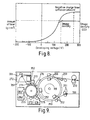
- Fig. 8 shows the relationship between the development voltage, the amount of negatively charged toner material which is applied, and the image concentration or density.
- the amount of toner material increases with the development voltage up to 250 V but the image density becomes saturated at 150 V.
- Application of excess amounts of toner material will not only waste toner material but result in an offset during the fixing process, so that the optimal development voltage is around 150 V.
- Cyan toner material is not applied to other areas with a development voltage of less than -150 V.
- the development roll 274R of the second development processor 274 is set at a development bias voltage of -650 V.
- the development processor 274 contains a carrier and magenta toner material.
- the magenta toner material is positively charged by friction with the carrier.
- the development voltage with respect to the second development processor 274 is set to be -150 V; for the areas with the surface potential of -900 V where blue is to be produced, the development voltage is set to be -250 V; and for other areas the development voltage is set to be more than 150 V.
- the relationship between the development voltage, the amount of positively charged toner material transferred, and the image density has the characteristic shown in Fig. 8 but with the polarity of the development voltage reversed.
- the right half of the area where blue is to be recorded receives an excess amount of magenta toner material, increasing the thickness of the toner material layer, as shown in Fig. 1(b).
- Magenta toner material is not transferred to other areas with a development voltage of more than 150 V.
- cyan toner material in the first development processor 273 nor magenta toner material in the second development processor 274 is applied to the areas with the surface potential of -500 V where white is to be produced, so that the area presents the white of the paper.
- the negative cyan toner material is positively charged by the charger 271.
- the toner image 256 thus formed having two colors (namely cyan and magenta), is electrostatically transferred at the transfer point 254 to the paper 300 by the transfer activator 257 of negative potential. Some of the toner material remains on the photosensitive drum, and electrical charge is removed from this residual toner material by the charge remover 276 and cleared by the cleaner 277.
- the photosensitive drum 265 is charged to -800 V at the surface by the charger 281.
- the area on the drum surface where yellow is to be produced is exposed so that the surface potential will be -200 V; the area where white is to be produced is exposed so that the surface potential will be -500 V; and the area where black is to be produced is not exposed, leaving the surface potential at -800 V.
- Negatively charged yellow toner material from the first development processor 283, whose bias potential is set to 350 V, is applied to the area where yellow is to be produced.
- the toner image 266 thus formed of two colors (namely yellow and black), is transferred at the transfer point 264 onto the two-color toner image 256 composed of cyan and magenta which has already been formed on the paper 300.
- green and red are produced by transferring yellow toner material over cyan toner material and transferring yellow toner material over the magenta toner material, as shown in Table 1.
- the toner images 256 and 266 on the paper 300 are fused together and fixed to the paper by the fixing device 270 to produce colors as shown in Table 1.
- the lines of the toner material are pressed by rolls so that they widen slightly. The degree to which the toner material widens depends on the thickness of the toner material layer. Table 2 shows the changes in the toner material line width measured during the process from development to fixing. After being developed (on photosensitive body) After being transferred (on paper) After being fixed (on paper) Vertical line 94 ⁇ 98 ⁇ 131 ⁇ Horizontal line 110 ⁇ 99 ⁇ 136 ⁇
- the embodiments of the invention discussed above provide two sets of exposure/development systems, which are operated in parallel. This increases the recording speed and allows the use of a continuous sheet of recording medium.
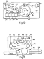
- Fig. 9 shows a photosensitive drum system and Fig. 10 a photosensitive belt system which make use of this arrangement.
- Fig. 9 only one photosensitive drum is used and the charger, charge remover and cleaner are assembled into a unit, making the apparatus smaller.
- Fig. 9 compounds which correspond to components of the embodiment of Fig. 1 are indicated by the same reference numerals.
- the paper 300 is fed between the paper guides 251 to the transfer drum 253 and charged by the charger 252 so that the paper is electrostatically attracted to the transfer drum 253.
- the transfer drum 253 rotates in the direction of arrow B and a toner image formed on the photosensitive drum 255 is transferred by the transfer activator 257 to the paper 300 on the transfer drum 253.
- the photosensitive drum 255 is charged evenly over its photosensitive surface by the charger 271 and then exposed by a beam whose intensity is varied by the exposing optical system 272 in dependence on the kind of toner materials to be transferred.
- colored toner materials are applied to the photosensitive body by the development processors 273, 283 to form a toner image, which is then transferred onto the paper 300 on the transfer drum 253 by the transfer activator 257.
- the paper to which toner material has been transferred remains attached to the transfer drum while making one revolution, after which further color toner material is transferred to the paper by the transfer activator.
- electrical charge is removed from the paper by the charge remover 258, the paper is peeled off the transfer drum by the separator claw 259 and the developed toner image is fused and fixed by the fixing device 270, applying heat and pressure to the paper.
- the paper is then discharged from the equipment.
- the photosensitive drum is freed of electrical charge by the charge remover 276 and cleared of remaining toner by the cleaner 277, after which an electrostatic latent image for the next color is formed on the photosensitive drum by the exposing optical system 272.
- the development processors 273, 283 are replaced with the development processors 274, 284, and the latent image is developed by the colored toner materials contained in these newly activated development processors.
- the developed image is transferred onto the recording paper by the transfer activator 257, as before.
- Changing the development processors may be done, according to commands from a control apparatus, by mechanically moving the two development processors horizontally or vertically or by rotating integrally assembled development processors.
- Fig. 10 shows an embodiment in which a photosensitive belt 253B is used in place of the photosensitive drum 253 of Fig. 9.
- Other components of the embodiment of Fig. 10 are similar to corresponding components of the embodiment of Fig. 9 and are indicated by the same reference numerals.
- One advantage of the embodiment of Fig. 10 is that, because the four development processors 273,274, 283,284 can all be arranged along the photosensitive belt 253B, unlike the embodiment of Fig. 9, they need not be moved to be switched into use. The operation of this construction is nearly the same as that of Fig. 9 and detailed description of this is therefore is omitted.
- Fig. 11 shows another embodiment of this invention. Components of this embodiment which correspond to the embodiment of Fig. 3 are indicated by the same reference numerals.
- the embodiment of Fig. 11 includes: four development processors 273, 274, 283, 284 arranged over one photosensitive belt 255B; an optical system which consists of a semiconductor laser 306, a polygon mirror 350 and a polarizer 355 and which exposes two locations at the same time using one light source; two chargers 271, 281; one recharger 275; one charge remover 276; one cleaner (not shown); a transfer drum 253; and a fixing device 270.
- the operation of this embodiment will now be described.
- the printer Upon receiving a record command and color information from the host computer, the printer picks up paper 300 from the paper hopper 300h and carries it to the transfer drum 253.
- This paper transport function is almost the same as that shown in Fig. 2 and hence detailed description thereof is omitted.
- the photosensitive body is the belt 255B in this embodiment but is not limited to this.
- a charger 271 is located upstream of the photosensitive belt 255B which uniformly charges the photosensitive belt 255B.
- the exposing device for exposing the photosensitive body surface charged by the charger 271 comprises a light source 306, a polygonal mirror 350 and a polarizer 355 that splits the light beam.
- the evenly charged photosensitive belt 255B is exposed to one of the split beams from the beam splitting means 355 of the exposing device, so that the photosensitive belt has a potential at which to develop the latent image with the toner materials of the development processors 273, 274. Then the photosensitive belt 255B is developed by the developers 273, 274. After passing the development processors 273, 274, the photosensitive belt is again charged uniformly by the charger 281 and is exposed by the other split beam to have a potential at which it is to be developed with the toner materials of the next development processors 283, 284. The photosensitive belt developed by the development processors 283, 284 is passed under the charge remover 275 to have a specified potential and the developed toner image is transferred at the transfer point to the paper 300 on the transfer roll 253.
- a transfer activator like the one shown in Fig. 3 is provided at this transfer point.
- the transferred toner image on the paper 300 is fixed by the fixing device 270, during which time the toner materials are mixed in the manner characteristic of this invention to produce desired colors. After the fixing, the photosensitive belt is cleared of remaining toner materials by the cleaner.
- Fig. 11 shows schematically that a single laser is used to generate two light beams, using a polarizing beam splitter 355 to enable the photosensitive belt 255B to be exposed at two places, adjacent the chargers 271 and 281 respectively.
- beam splitting arrangements can be used in any embodiment of the present invention in which exposures are needed at two separate locations, and a way of achieving this will now be described in more detail, with reference to Fig. 12.
- Fig. 12 illustrates an arrangement in which a single laser 250 is used to expose two photosensitive drums 255 and 265 as in the embodiment of Fig. 3.
- this arrangement is also applicable to arrangements in which there are photosensitive belts, such as the embodiment of Fig. 4, or where a photosensitive belt or drum has to be exposed in separate locations, as in the embodiment of Fig. 11.
- a light beam from a laser 306 is collimated by a collimator lens 400 and passes through a polarizing light switch 401.
- a controller 402 is connected to the laser 306 and light switch 401.
- This controller has two functions. Firstly, it controls the intensity of the light beam from the laser 306. Secondly, it varies the angle of polarization of the beam passing through the polarizing light switch 401. The effect of this will be discussed in more detail later.
- the light beam After the light beam has passed through the light switch 401, it passes through a cylindrical lens 403 and is incident on a polygon mirror 350. That polygon mirror reflects the light beam through an f- ⁇ lens 404 and the light is then incident on the polarizing beam splitter 355.
- the polarizing beam splitter 355 is arranged to pass light which is polarized in one direction, and to reflect light which is polarized in a perpendicular direction. Hence, the light beam 405 which is incident on the polarizing beam splitter 355 is split into two beams 406,407, which are incident on the photosensitive drums 255,265 respectively.
- the controller 402 controls the light switch 401 so that the light beam is polarized in the direction which is passed by the polarizing beam splitter 355, all the light from the laser 306 will be incident on the photosensitive drum 255. If the controller 402 controls the light switch 401 to polarize the beam in a perpendicular direction, then all of the light from the laser 306 will be reflected by the polarizing beam splitter 355 and will therefore be incident on the other photosensitive drum 265. If the light switch 401 is controlled by the controller 402 so that the direction of polarization is intermediate these two extremes, then some of the light in the beam 405 will pass to the first photosensitive drum 255 and the rest of the light will pass to the second photosensitive drum 265.
- each photosensitive drum 255,265 may be exposed by such that dots for toner material receive different intensities and widths of exposure, to enable exposure in the manner shown in Fig. 1 to be achieved.
- the polarized light switch 401 and its controller 402 are currently expensive. Therefore, another arrangement for achieving a similar effect may make use of two lasers 306,306A, as shown in Fig. 13.
- components which correspond to components of Fig. 12 are indicated by the same reference numerals.
- light from the laser 306 which has been collimated by the lens 400 passes through a polarizer 408 and passes through a light mixer 409.
- the light mixer 409 receives light from the second laser 306a, which has been collimated by a lens 400a and polarized by a polarizer 408a.
- the polarizers 408 and 408a are arranged such that the directions of polarization thereof are perpendicular.
- the light mixer 409 then mixes the two light beams to generate a single light beam 410 which is then incident on the polygon lens 350 and passes to the photosensitive drums 255,265 in the same way as in the arrangement of Fig. 12.
- the beam 410 may be arranged to have all its lights polarized in one or other perpendicular direction, or be composed of a mixture of light of the two polarizing directions.
- the intensities of the light in the beams 406,407 from the polarizing beam splitter 355 can be adjusted in the same way as in the arrangement of Fig. 12.
- the polarizing beam splitter 355 can be replaced by a half-mirror and perpendicular polarizers if desired, with the same effects as in the arrangements for Fig. 12 or Fig. 13.
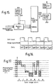
- Fig. 14 through Fig. 16 and Table 3 show another embodiment of this invention.
- Fig. 14 shows the overall configuration of this embodiment. Components of this embodiment which correspond to the embodiment of Fig. 3 are indicated by the same reference numerals.
- the signal is temporarily stored in the memory 301 in the printer control unit 210.
- the image signal is subjected to data conversion by the data convertor 1203 in synchronism with a synchronizing clock 303 and then sent to the laser diode drive circuit 1204.
- the photosensitive belt 255B is charged by the charger 271, exposed to a beam from the semiconductor laser 306 and then passed through four development processors 273, 274, 283, 284.
- the development processors contain color toners and is set at development bias potentials listed below.
- the developed toners are charged to the same polarity by the charger 275 and transferred to the paper 300 by the transfer activator 256.
- Fig. 15 shows the configuration of a control circuit for controlling the surface potential of the photosensitive body by the laser output.
- the RGB image signal from the memory 301 is sent, in synchronism with the dot synchronizing clock 303, to the address terminal of the convertor 1203 that has a data memory.
- a signal from the dot synchronizing clock 303 is also sent directly to the data convertor 1203.
- Table 3 shows the method of conversion carried out by the data convertor 1203 and Fig. 16 shows a timing chart for the data convertor 1203.
- the colors are identified as follows: C: cyan; M: magenta; Y: yellow; R: red; B: blue; K: black.
- the symbol N/A means that the data are not available
- the actual data is 8-bit digital data that corresponds to the laser drive current that generates the photosensitive body potential as shown in the table after exposure.
- the data convertor 1203 is preset with 8-bit binary data which represent laser drive currents for providing the exposed photosensitive body with potentials as shown in Table 3 after exposure.
- the image signal 400 is updated.
- the dot clock 303 is "1," the data convertor 1203 outputs data 1202 for the left half of the dot.
- the dot clock 303 is "0,” the data convertor 1203 outputs data for the right half of the dot.
- the variable current source 307 is a high-speed digital-analog convertor which supplies a current corresponding to the data 1202 to the semiconductor laser 306.
- Fig. 17 shows the relationship between the photosensitive body surface potential and the color toner materials.
- the photosensitive body surface charged uniformly to a potential of -900 V is exposed by a beam from the semiconductor laser 306 whose intensity corresponds to the color to be produced so that the surface will be charged to seven levels of potential between -100 V and -900 V. Since each development processor is set at the development bias, the color produced toner is described below.
- this embodiment although yellow Y cannot be produced, a significantly wide gamut of colors can be produced by suitably changing the proportions of the three color toners contained in the four development processors.
- this embodiment can be used for multi-color applications. Since this embodiment produces a multi-color latent image in a single exposure, there is theoretically no registration error between different color images (which error has disadvantageous effects on the image quality) and thus very high quality images can be obtained. Furthermore, the recording speed is improved.
- a subtractive color process can be performed in a single run of exposure/development, so that many colors can be produced.
- a subtractive color process can be performed in a single run of exposure/development, so that many colors can be produced.
Landscapes
- Physics & Mathematics (AREA)
- General Physics & Mathematics (AREA)
- Optics & Photonics (AREA)
- Engineering & Computer Science (AREA)
- Multimedia (AREA)
- Signal Processing (AREA)
- Color Electrophotography (AREA)
- Dot-Matrix Printers And Others (AREA)
- Color, Gradation (AREA)
Claims (20)
- Imprimante élecrophotographique en couleur comprenant :caractérisé en ce que :un corps photosensible (255, 255B) ;un moyen d'exposition (300, 350, 351, 352) pour exposer ledit corps photosensible (255, 255B),ledit moyen d'exposition (300, 350, 351, 352) étant agencé pour exposer ledit corps photosensible (255, 255B) pour former un motif d'exposition ayant un certain nombre d'éléments d'image, lesdits éléments d'image ayant un certain nombre de niveaux de tension; etun moyen développeur (273, 274) pour appliquer un premier matériau d'encre d'une première couleur et un second matériau d'encre d'une seconde couleur auxdits éléments d'image respectifs ;ladite pluralité de niveaux de tension comprend un niveau de tension de base, un premier niveau de tension positif par rapport audit niveau de tension de base à des premiers desdits éléments d'image, un second niveau de tension positif par rapport à la fois audit premier niveau de tension et audit niveau de base à des seconds desdits éléments d'image, un troisième niveau de tension négatif par rapport audit niveau de tension de base à des troisièmes desdits éléments d'image et un quatrième niveau de tension négatif par rapport à la fois audit troisième niveau de tension et audit niveau de tension de base à des quatrièmes desdits éléments d'image, de la sorte les premiers de la pluralité d'éléments d'images ont une première épaisseur dudit premier matériau d'encre, les seconds desdits éléments d'images ont une seconde épaisseur desdits premiers matériaux d'encre, les troisièmes desdits éléments d'images ont ladite première épaisseur dudit second matériau d'encre et les quatrièmes desdits éléments d'images ont ladite seconde épaisseur dudit second matériau d'encre, avec des seconds et quatrièmes desdits éléments d'images étant adjacents ; ladite seconde épaisseur étant supérieure à ladite première épaisseur ; etun moyen pour fixer ledit matériau d'encre sur un support d'enregistrement de sorte que le matériau d'encre desdits second et quatrième matériau d'encre se mélange, pour produire une couleur mélangée.
- Imprimante selon la revendication 1, dans laquelle le moyen d'exposition précité (300, 350, 351, 352)est agencé pour former la pluralité précitée d'éléments d'images de sorte que les premiers et troisièmes de la pluralité précitée d'éléments d'images ont une première largeur et les seconds et quatrièmes de ladite pluralité d'élements d'images ont une seconde largeur.
- Imprimante selon l'une quelconque des revendications précédentes, ayant un moyen de transfert (253, 257) pour transférer les premier et second matériaux d'encre précités à un support d'enregistrement (300).
- Imprimante selon la revendication 1 ou la revendication 2, ayant d'autres moyens d'exposition (300, 350, 351, 352) pour exposer le corps photosensible précité (255B)pour former un autre motif d'exposition sur celui, ci,l'autre motif d'exposition ayant un certain nombre d'autres élements d'image et l'autre moyen développeur (283, 284) étant agencé pour appliquer un troisième matériau d'encre d'une troisième couleur et un quatrième matériau d'encre d'une quatrième couleur au premier et second de ladite pluralité d'autres éléments d'images.
- Imprimante selon la revendication 4, ayant un moyen de transfert (253, 257) pour transférer simultanément les premier, second, troisième et quatrième matériaux d'encre précités simultanément du corps photosensible précité (255B) à un support d'enregistrement (300).
- Imprimante selon la revendication 4 ou la revendication 5 selon laquelle au moins certains desdits premiers de ladite pluralité d'autres éléments d'images coincident avec au moins certains des premiers et seconds de la pluralité précitée d'élements d'images sur le corps photosensible précité (255B).
- Imprimante selon l'une quelconque des revendications 1 à 3, dans laquelle le moyen développeur précité est agencé pour appliquer un troisième matériau d'encre d'une troisième couleur à au moins certains des premiers et seconds précités de la pluralité précitée d'éléments d'images.
- Imprimante selon la revendication 7, dans laquelle le développeur précité (300, 350, 351, 352) est agencé pour appliquer le troisième matériau d'encre précité à au moins certains des troisièmes et quatrièmes précités de la pluralité précitée d'éléments d'images.
- Imprimante selon la revendication 1 ou la revendication 2, dans laquelle le moyen d'exposition précité (300, 350, 351, 352) est agencé pour exposer davantage le corps photosensible précité (255, 255B) pour former un autre motif d'exposition ayant un certain nombre d'autres éléments d'images, et ledit moyen développeur est agencé pour appliquer un troisième matériau d'encre d'une troisième couleur et un quatrième matériau d'encre d'une quatrième couleur aux premiers et seconds de la pluralité précitée d'autres éléments d'images.
- Imprimante selon la revendication 9, ayant un moyen de transfert pour transférer les premier et second matériaux d'encre précités à un support d'enregistrement (300) et pour subséquemment transférer les troisième et quatrième matériaux d'encre précités audit support d'enregistrement (300).
- Imprimante selon la revendication 10, dans laquelle le moyen de transfert précité est agencé pour transférer les premier, second, troisième et quatrième matériaux d'encre précités au support d'enregistrement précité (300) de sorte qu'au moins une partie dudit troisième matériau d'encre est coincidente avec une partie desdits premier et second matériau d'encre sur le support d'enregistrement (300).
- Imprimante électrophotographique en couleur selon la revendication 1, dans laquelle :le corps photosensible précité comprend des premier et second corps photosensibles (255, 265)le moyen d'exposition précité comprend des premier et second moyens d'exposition (300, 350, 351, 352) pour exposer respectivement lesdits premier et second corps photosensibles (255, 265) pour former respectivement des première et seconde images latentes ;ledit moyen développeur comprend des premier et second moyens développeur (273, 274) associés audit premier corps photosensible (255), ledit premier moyen développeur (273) étant agencé pour appliquer le premier matériau d'encre précité de la première couleur précitée à ladite première image latente sur ledit premier corps photosensible (255) sur la base de ladite exposition par ledit premier moyen d'exposition (300, 350, 351, 352), ledit second moyen développeur (274) étant agencé pour appliquer le second matériau d'encre précité de la seconde couleur précitée à ladite première image latente sur ledit premier corps photosensible (255) sur la base de ladite exposition par ledit moyen d'exposition (300, 350, 351, 352) ;l'imprimante comprend de plus des troisième et quatrième moyens développeurs (283, 284) associés audit second corps photosensible (265), ledit troisième moyen développeur (283) étant agencé pour appliquer un troisième matériau d'encre d'une troisième couleur à ladite seconde image latente sur ledit second corps photosensible (274) sur la base de ladite exposition par ledit second moyen d'exposition (300, 350, 351, 352), ledit quatrième moyen développeur (284) étant agencé pour appliquer un quatrième matériau d'encre d'une quatrième couleur à ladite seconde image latente sur ledit second corps photosensible (274) sur la base de ladite exposition par le second moyen d'exposition (300, 350, 351, 352) et un moyen de transfert pour transférer lesdites première et seconde images développées correspondant auxdites images latentes respectives séquentiellement à un support d'enregistrement (300).
- Imprimante électrophotographique en couleur selon la revendication 1, dans laquelle :le moyen d'exposition précité (300, 350, 351, 352) est agencé pour exposer le corps photosensible précité (255, 255B) pour former une première image latente sur celui, ci et subséquemment exposer davantage ledit corps photosensible (255, 255B) pour former une seconde image latente sur celui-ci ;le moyen développeur précité comprend des premier et second moyens développeur (273, 274) associés audit corps photosensible (255, 255B), les premier et second moyens développeur (273, 274) étant agencés respectivement pour appliquer le premier matériau d'encre précité de la première couleur précitée et le second matériau d'encre précité de la seconde couleur précitée, à ladite première image latente sur ledit corps photosensible (255, 255B) ;l'imprimante comprend de plus un moyen de transfert (257) pour transférer les premier et second matériaux d'encre précités à un support d'enregistrement avant la formation de ladite seconde image latente par ledit moyen d'exposition (300, 350, 351, 352), des troisième et quatrième moyens développeur associés audit corps photosensible (255, 255B), lesdits troisième et quatrième moyens développeurs étant agencés pour appliquer respectivement un troisième matériau d'encre d'une troisième couleur et un quatrième matériau d'encre d'une quatrième couleur à ladite seconde image latente sur ledit corps photosensible (255, 255B), ledit moyen de transfert (257) étant agencé pour transférer lesdits troisième et quatrième matériaux d'encre audit support d'enregistrement.
- Imprimante électrophotographique en couleurs selon la revendication 1, dans laquelle :le moyen d'exposition précité comprend un premier moyen d'exposition (300, 350, 351, 352) agencé pour exposer le corps photosensible précité (255, 255B) pour former une première image latente sur celui, ci.le moyen développeur précité comprend des premier et second moyens développeur (273, 274) associés audit corps photosensible (273, 274), lesdits premier et second moyens développeur (273, 274) étant agencés pour appliquer respectivement le premier matériau d'encre précité de la première couleur précitée et second matériau d'encre précité de la seconde couleur précitée à ladite première image latente sur ledit corps photosensible ; etladite imprimante comprend de plus un second moyen d'exposition (300, 350, 351, 352) pour exposer davantage ledit corps photosensible (255, 255B) pour former une seconde image latente sur celui, ci, des troisième et quatrième moyens développeur (283, 284) associés audit corps photosensible (255, 255B), lesdits troisième et quatrième moyens développeur (283, 284) étant agencés pour appliquer respectivement un troisième matériau d'encre d'une troisième couleur et un quatrième matériau d'encre d'une quatrième couleur à ladite seconde image latente sur ledit corps photosensible (255, 255B), et un moyen de transfert (257) pour simultanément transférer lesdits premier, second, troisième et quatrième matériaux d'encre dudit corps photosensible à un support d'enregistrement (300).
- Imprimante selon la revendication 14 selon laquelle les premier et second moyens d'exposition précités (300, 350, 351, 352) ont une source de lumière commune.
- Imprimante selon la revendication 15, dans laquelle les premier et second moyens d'exposition précités ((300, 350, 351, 352) ont des sources de lumière séparées et un moyen de balayage commun.
- Procédé d'impression électrophotographique en couleur, comprenant :caractérisé en ce que :exposer un corps photosensible (255, 255B), pour former un motif d'exposition ayant un certain nombre d'éléments d'images, lesdits éléments d'images ayant un certain nombre de niveaux de tension ;appliquer (273, 274) un premier matériau d'encre d'une première couleur et un second matériau d'encre d'une seconde couleur aux éléments respectifs desdits éléments d'images ;fixer le matériau d'encre sur un support d'enregistrement ;ladite pluralité de niveaux de tension comprend un niveau de tension de fond, un premier niveau de tension étant positif par rapport audit niveau de tension de fond auxdits seconds à des premiers desdits éléments d'images, un second niveau de tension étant positif par rapport à la fois audit premier niveau de tension et audit niveau de fond auxdits seconds desdits éléments d'images, un troisième niveau de tension étant négatif par rapport audit niveau de tension de fond à des troisièmes desdits éléments d'images et un quatrième niveau de tension étant négatif par rapport à la fois au troisième niveau de tension et audit niveau de tension de fond à des quatrièmes desdits éléments d'images, de la sorte les premiers de la pluralité d'élements d'images ont une première épaisseur dudit premier matériau d'encre, les seconds desdits éléments d'images ont une seconde épaisseur desdits premiers matériaux d'encre, les troisièmes desdits éléments d'image ont une première épaisseur dudit second matériau d'encre et les quatrièmes des éléments d'images ont ladite seconde épaisseur dudit second matériau d'encre, avec les seconds et quatrièmes desdits éléments d'images étant adjacents, ladite seconde épaisseur étant supérieure à ladite première épaisseur ; etle fixage dudit matériau d'encre est tel que le matériau d'encre desdits second et quatrième matériaux d'encre adjacents se mélange pour produire une couleur mélangée.
- Procédé selon la revendication 17, dans lequel:des premier et second corps photosensibles (255, 265) sont exposés à des première et seconde expositions pour former, respectivement, des première et seconde images latentes ;le premier matériau d'encre précité de la première couleur précitée pour ladite première image latente est appliqué (265) audit premier corps photosensible (255) sur la base de ladite première exposition ;le second matériau d'encre précité pour la seconde couleur précitée pour la première image latente est appliqué (274) audit premier corps photosensible (255) sur la base de ladite première exposition ;un troisième matériau d'encre d'une troisième couleur pour ladite seconde image latente est appliqué (283) audit second corps photosensible (255) sur la base de ladite seconde exposition ;un quatrième matériau d'encre d'une quatrième couleur pour ladite seconde image latente est appliqué (284) audit second corps photosensible (255) sur la base de ladite seconde exposition ;lesdites première et seconde images développées correspondant auxdites images latentes respectives sont transférées séquentiellement (257, 267) à un support d'enregistrement (300).
- Procédé selon la revendication 17, dans lequel :le corps photosensible (255, 255B) est exposé pour former sur celui, ci une première image latente et exposé subséquemment pour former sur celui-ci une seconde image latente ;le premier matériau d'encre précité de la première couleur précitée et le second matériau d'encre de la seconde couleur précitée pour ladite première image latente sont appliqués audit corps photosensible (255, 255B) ;lesdits premier et second matériaux d'encre sont transférés (267) à un support d'enregistrement (300) avant la formation de ladite seconde image latente ;un troisième matériau d'encre d'une troisième couleur et un quatrième matériau d'encre d'une quatrième couleur pour ladite seconde image latente sont appliqués (273, 274) audit corps photosensible (255, 255B) ;lesdits troisième et quatrième matériaux d'encre sont transférés (267) audit support d'enregistrement (300).
- Procédé selon la revendication 17, dans lequel :le corps photosensible précité (255B) est exposé pour former sur celui, ci une première image latente ;le premier matériau d'encre de la première couleur précitée et le second matériau d'encre de la seconde couleur précitée pour ladite première image latente sont appliqués (273, 274) audit corps photosensible (255B) ;ledit corps photosensible (255B) est davantage exposé pour former sur celui, ci une seconde image latente ;un troisième matériau d'encre d'une troisième couleur et un quatrième matériau d'encre d'une quatrième couleur pour ladite seconde image latente sont appliqués (283, 284) audit corps photosensible (255B) ;les premier, second, troisième et quatrième matériaux d'encre sont transférés simultanément (267) à un support d'enregistrement (300).
Applications Claiming Priority (2)
| Application Number | Priority Date | Filing Date | Title |
|---|---|---|---|
| JP5003103A JPH06206348A (ja) | 1993-01-12 | 1993-01-12 | カラー電子写真プリンタ |
| JP3103/93 | 1993-01-12 |
Publications (2)
| Publication Number | Publication Date |
|---|---|
| EP0606982A1 EP0606982A1 (fr) | 1994-07-20 |
| EP0606982B1 true EP0606982B1 (fr) | 1998-06-17 |
Family
ID=11548020
Family Applications (1)
| Application Number | Title | Priority Date | Filing Date |
|---|---|---|---|
| EP94300069A Expired - Lifetime EP0606982B1 (fr) | 1993-01-12 | 1994-01-06 | Une imprimante électrophotographique en couleur et un procédé d'impression utilisant une telle imprimante |
Country Status (5)
| Country | Link |
|---|---|
| US (1) | US5550626A (fr) |
| EP (1) | EP0606982B1 (fr) |
| JP (1) | JPH06206348A (fr) |
| CA (1) | CA2113020C (fr) |
| DE (1) | DE69411041T2 (fr) |
Families Citing this family (8)
| Publication number | Priority date | Publication date | Assignee | Title |
|---|---|---|---|---|
| US5995124A (en) * | 1995-01-30 | 1999-11-30 | Hitachi, Ltd. | Color electrophotographic printer with belt control |
| JPH1031342A (ja) * | 1996-05-15 | 1998-02-03 | Sharp Corp | 画像形成装置 |
| JPH1078688A (ja) * | 1996-09-05 | 1998-03-24 | Hitachi Ltd | カラー画像形成装置 |
| US6147698A (en) * | 1997-05-29 | 2000-11-14 | International Business Machines Corporation | Density control for a printer |
| US5837408A (en) * | 1997-08-20 | 1998-11-17 | Xerox Corporation | Xerocolography tandem architectures for high speed color printing |
| JP3984696B2 (ja) * | 1998-01-30 | 2007-10-03 | キヤノン株式会社 | 画像形成装置および画像形成方法 |
| US7505206B2 (en) * | 2006-07-10 | 2009-03-17 | Taiwan Semiconductor Manufacturing Company | Microlens structure for improved CMOS image sensor sensitivity |
| JP7032240B2 (ja) * | 2018-05-28 | 2022-03-08 | シャープ株式会社 | 現像装置および画像形成装置 |
Family Cites Families (12)
| Publication number | Priority date | Publication date | Assignee | Title |
|---|---|---|---|---|
| JPS60185971A (ja) * | 1984-03-05 | 1985-09-21 | Matsushita Graphic Commun Syst Inc | 液体現像によるカラ−現像方法 |
| EP0181981B1 (fr) * | 1984-11-23 | 1990-04-04 | Mitsubishi Denki Kabushiki Kaisha | Procédé d'impression par transfert thermique et tête thermique associée |
| JPH06100863B2 (ja) * | 1985-01-29 | 1994-12-12 | 富士通株式会社 | 多色記録装置 |
| JPS61223853A (ja) * | 1985-03-29 | 1986-10-04 | Konishiroku Photo Ind Co Ltd | 多色画像形成方法 |
| US4731634A (en) * | 1986-11-03 | 1988-03-15 | Xerox Corporation | Apparatus for printing black and plural highlight color images in a single pass |
| JPH0212273A (ja) * | 1988-06-30 | 1990-01-17 | Mita Ind Co Ltd | 多色画像形成装置 |
| JPH02105175A (ja) * | 1988-10-14 | 1990-04-17 | Canon Inc | 多色画像形成装置 |
| JPH087475B2 (ja) * | 1990-01-29 | 1996-01-29 | 富士ゼロックス株式会社 | カラー画像形成装置及びその使用方法 |
| US5122843A (en) * | 1990-02-15 | 1992-06-16 | Minolta Camera Kabushiki Kaisha | Image forming apparatus having developing devices which use different size toner particles |
| US5194905A (en) * | 1990-11-29 | 1993-03-16 | Xerox Corporation | Color printer apparatus for printing selected portions of latent images in various colors |
| US5121171A (en) * | 1991-01-09 | 1992-06-09 | Xerox Corporation | Hybrid color printing machine |
| US5223906A (en) * | 1992-08-03 | 1993-06-29 | Xerox Corporation | Four color toner single pass color printing system using two tri-level xerographic units |
-
1993
- 1993-01-12 JP JP5003103A patent/JPH06206348A/ja active Pending
-
1994
- 1994-01-06 US US08/177,991 patent/US5550626A/en not_active Expired - Fee Related
- 1994-01-06 DE DE69411041T patent/DE69411041T2/de not_active Expired - Fee Related
- 1994-01-06 EP EP94300069A patent/EP0606982B1/fr not_active Expired - Lifetime
- 1994-01-07 CA CA002113020A patent/CA2113020C/fr not_active Expired - Fee Related
Also Published As
| Publication number | Publication date |
|---|---|
| CA2113020A1 (fr) | 1994-07-13 |
| DE69411041T2 (de) | 1999-03-25 |
| JPH06206348A (ja) | 1994-07-26 |
| CA2113020C (fr) | 1996-12-24 |
| US5550626A (en) | 1996-08-27 |
| DE69411041D1 (de) | 1998-07-23 |
| EP0606982A1 (fr) | 1994-07-20 |
Similar Documents
| Publication | Publication Date | Title |
|---|---|---|
| KR100283815B1 (ko) | 화상형성장치 | |
| US5438437A (en) | Image forming apparatus with exposure, size, and position correction for pixels | |
| US4578331A (en) | Color image forming method | |
| JP2788514B2 (ja) | グレイスケール及び疑似カラー画像形成方法 | |
| EP0582454B1 (fr) | Système d'impression couleur à quatre, toners colorés, à passage simple et utilisant deux unités xérographiques à trois niveaux | |
| US5221954A (en) | Single pass full color printing system using a quad-level xerographic unit | |
| US5241356A (en) | Method and apparatus for minimizing the voltage difference between a developed electrostatic image area and a latent electrostaic non-developed image | |
| US6819902B2 (en) | Image forming apparatus with interchangeable developing devices | |
| CA2113020C (fr) | Imprimante couleur electrophotographique et methode d'impression faisant appel a ladite imprimante | |
| US6434345B2 (en) | Image forming apparatus | |
| US5716744A (en) | Dual beam color electrophotographic apparatus | |
| US7782355B2 (en) | Image forming apparatus using a plurality of lasers with a varying exposure ratio | |
| US5515155A (en) | Method and apparatus for establishing exposure and developer set points for color image formation | |
| US5194351A (en) | Single pass digital xerographic process color reproduction | |
| EP0735433B1 (fr) | Unité xérographique à cinq niveaux | |
| JP3738124B2 (ja) | 多色画像形成装置 | |
| JP3345448B2 (ja) | カラー画像形成装置 | |
| JP3058695B2 (ja) | カラー電子写真プリンタ | |
| JP3130916B2 (ja) | 多色画像形成装置 | |
| JP4191892B2 (ja) | カラー画像形成装置 | |
| JPH0554676B2 (fr) | ||
| JPS6017770A (ja) | 電子写真によるカラ−画像記録方法 | |
| JPWO1996024091A1 (ja) | カラー電子写真プリンタ | |
| JPH06105128A (ja) | カラー画像形成装置 | |
| JPH08227198A (ja) | 単一パス、デュアルドラムのフルカラープリントシステム |
Legal Events
| Date | Code | Title | Description |
|---|---|---|---|
| PUAI | Public reference made under article 153(3) epc to a published international application that has entered the european phase |
Free format text: ORIGINAL CODE: 0009012 |
|
| 17P | Request for examination filed |
Effective date: 19940127 |
|
| AK | Designated contracting states |
Kind code of ref document: A1 Designated state(s): DE IT NL |
|
| 17Q | First examination report despatched |
Effective date: 19961121 |
|
| GRAG | Despatch of communication of intention to grant |
Free format text: ORIGINAL CODE: EPIDOS AGRA |
|
| GRAG | Despatch of communication of intention to grant |
Free format text: ORIGINAL CODE: EPIDOS AGRA |
|
| GRAH | Despatch of communication of intention to grant a patent |
Free format text: ORIGINAL CODE: EPIDOS IGRA |
|
| GRAH | Despatch of communication of intention to grant a patent |
Free format text: ORIGINAL CODE: EPIDOS IGRA |
|
| GRAA | (expected) grant |
Free format text: ORIGINAL CODE: 0009210 |
|
| AK | Designated contracting states |
Kind code of ref document: B1 Designated state(s): DE IT NL |
|
| REF | Corresponds to: |
Ref document number: 69411041 Country of ref document: DE Date of ref document: 19980723 |
|
| ITF | It: translation for a ep patent filed | ||
| PGFP | Annual fee paid to national office [announced via postgrant information from national office to epo] |
Ref country code: NL Payment date: 19990129 Year of fee payment: 6 |
|
| PGFP | Annual fee paid to national office [announced via postgrant information from national office to epo] |
Ref country code: DE Payment date: 19990329 Year of fee payment: 6 |
|
| PLBE | No opposition filed within time limit |
Free format text: ORIGINAL CODE: 0009261 |
|
| STAA | Information on the status of an ep patent application or granted ep patent |
Free format text: STATUS: NO OPPOSITION FILED WITHIN TIME LIMIT |
|
| 26N | No opposition filed | ||
| PG25 | Lapsed in a contracting state [announced via postgrant information from national office to epo] |
Ref country code: NL Free format text: LAPSE BECAUSE OF NON-PAYMENT OF DUE FEES Effective date: 20000801 |
|
| NLV4 | Nl: lapsed or anulled due to non-payment of the annual fee |
Effective date: 20000801 |
|
| PG25 | Lapsed in a contracting state [announced via postgrant information from national office to epo] |
Ref country code: DE Free format text: LAPSE BECAUSE OF NON-PAYMENT OF DUE FEES Effective date: 20001101 |
|
| PG25 | Lapsed in a contracting state [announced via postgrant information from national office to epo] |
Ref country code: IT Free format text: LAPSE BECAUSE OF NON-PAYMENT OF DUE FEES;WARNING: LAPSES OF ITALIAN PATENTS WITH EFFECTIVE DATE BEFORE 2007 MAY HAVE OCCURRED AT ANY TIME BEFORE 2007. THE CORRECT EFFECTIVE DATE MAY BE DIFFERENT FROM THE ONE RECORDED. Effective date: 20050106 |