EP0607018B1 - Vorrichtung zum Anzeigen der Zeit auf einem Schirm - Google Patents
Vorrichtung zum Anzeigen der Zeit auf einem Schirm Download PDFInfo
- Publication number
- EP0607018B1 EP0607018B1 EP94300183A EP94300183A EP0607018B1 EP 0607018 B1 EP0607018 B1 EP 0607018B1 EP 94300183 A EP94300183 A EP 94300183A EP 94300183 A EP94300183 A EP 94300183A EP 0607018 B1 EP0607018 B1 EP 0607018B1
- Authority
- EP
- European Patent Office
- Prior art keywords
- timing
- time information
- symbol
- symbols
- variable
- Prior art date
- Legal status (The legal status is an assumption and is not a legal conclusion. Google has not performed a legal analysis and makes no representation as to the accuracy of the status listed.)
- Expired - Lifetime
Links
- 238000000034 method Methods 0.000 claims description 12
- 239000003086 colorant Substances 0.000 claims description 5
- 238000010586 diagram Methods 0.000 description 10
- 230000008569 process Effects 0.000 description 9
- 230000004044 response Effects 0.000 description 4
- 230000006870 function Effects 0.000 description 2
- 238000012986 modification Methods 0.000 description 2
- 230000004048 modification Effects 0.000 description 2
- 230000008859 change Effects 0.000 description 1
- 239000011159 matrix material Substances 0.000 description 1
Images


Classifications
-
- H—ELECTRICITY
- H04—ELECTRIC COMMUNICATION TECHNIQUE
- H04N—PICTORIAL COMMUNICATION, e.g. TELEVISION
- H04N21/00—Selective content distribution, e.g. interactive television or video on demand [VOD]
- H04N21/40—Client devices specifically adapted for the reception of or interaction with content, e.g. set-top-box [STB]; Operations thereof
- H04N21/47—End-user applications
- H04N21/485—End-user interface for client configuration
-
- G—PHYSICS
- G04—HOROLOGY
- G04G—ELECTRONIC TIME-PIECES
- G04G9/00—Visual time or date indication means
- G04G9/0058—Visual time or date indication means using a cathode ray tube as display device
-
- H—ELECTRICITY
- H04—ELECTRIC COMMUNICATION TECHNIQUE
- H04N—PICTORIAL COMMUNICATION, e.g. TELEVISION
- H04N21/00—Selective content distribution, e.g. interactive television or video on demand [VOD]
- H04N21/40—Client devices specifically adapted for the reception of or interaction with content, e.g. set-top-box [STB]; Operations thereof
- H04N21/47—End-user applications
- H04N21/478—Supplemental services, e.g. displaying phone caller identification, shopping application
Definitions
- the present invention generally relates to the field of display systems for displaying time on a screen, and more particularly, to a display apparatus which displays an analog clock image on a screen.
- time display or timer reservation
- a digital clock is displayed on a screen.
- analog type clock displays find it difficult to quickly read the time from digital clock displays. As a result, they become uncomfortable using the timer reservation system.
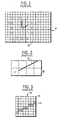
- Figure 1 is a diagram showing an example of an analog clock display on a television screen as described in Japanese laid-open patent No. S62-66779.
- Japanese laid-open patent No. Sl-107187 describes an example of producing display characters for displaying an analog clock as in Figure 1.
- Figure 2 is a diagram showing an example of the display configuration of a clock hand on television screen 81 in Figure 1
- Figure 3 is a diagram showing one of unit characters 82 in Figure 2 which includes a plurality of sub-unit characters.
- hand 83 (representing either the short or long hand) is displayed by arranging unit characters 82 in the form of a matrix.
- one unit character 82 includes, for instance, 8 rows and 8 columns (64) of sub-unit characters 84.
- Each of sub-unit characters 84 is arranged so that a part of hand 83 is formed by the combination of sub-unit characters 84 having different and distinguishable color (like the shaded dots in Figure 3) from others.
- Another object of the present invention is to provide an analog clock display apparatus which can accurately show the hour and minute to which short and long hands point.
- a display apparatus displays an analog clock image which has twelve timing symbols representing, for example, the numbers 1 to 12 and a pair of long and short hands. Colors of the twelve timing symbols are designated by control data so that first and second symbols respectively indicated by the long and short hands are displayed in a different color from other symbols.
- Figure 1 is a diagram showing an example of an analog clock display on a television screen.
- Figure 2 is a diagram showing an example of the display configuration of a clock hand on television screen 81 in Figure 1.
- Figure 3 is a diagram showing one of unit characters 82 in Figure 2 which includes a plurality of sub-unit characters.
- Figure 4 is a block diagram illustrating a time display apparatus in accordance with an embodiment of the present invention, which is applied to a television receiver.
- FIG. 5 is an illustration of the keyboard connected with key input reception circuit 4 in Figure 4.
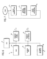
- Figure 6 is a block diagram illustrating the control circuit 3 in Figure 4 in detail.
- Figure 7 is a flow-chart for executing basic operations in control circuit 3 of Figure 6.
- Figure 8 is a flow-chart for producing the instruction data in order to display an analog clock image in the process of step S 3 in Figure 7.
- Figure 4 is a block diagram illustrating a time display apparatus in accordance with an embodiment of the present invention, which is applied to a television receiver in order to display the present time.
- the television signals received by antenna 1 are supplied to tuning circuit 2.
- the video signal corresponding to a desired channel designated by control circuit 3 is selected out of several television signals, and the extracted video signal is amplified.
- Key input reception circuit 4 is connected with a keyboard, which will be discussed further below, for receiving key inputs from a user and for transmitting command data (C) corresponding to the key inputs to control circuit 3.
- control circuit 3 which includes a microcomputer supplies instruction data (I1) or (I2) to either of tuning circuit 2 or on- screen display circuit 6, respectively.
- the video signal (V) tuned by tuning circuit 2 is supplied to color signal reproduction circuit 5.
- the video signal (V) is restored to primary color signals of red (R1), green (G1) and blue (B1), and these color signals are supplied to one of the input terminals of color signal switching circuit 7.
- on-screen display circuit 6 generates other primary color signals of red (R2), green (G2) and blue (B2) for displaying an analog clock image and other on-screen images based on the instruction data (I2).
- the color signals (R2), (G2) and (B2) are supplied to the other input terminal of color signal switching circuit 7.
- the color signal switching circuit 7 switches over and outputs the primary color signals supplied from one of color signal reproduction circuit 5 and on-screen display circuit 6, and supplies them to color picture tube 8.
- Color picture tube 8 displays a color image on the screen based on the primary color signals (R), (G) and (B) supplied from switching circuit 7.
- FIG. 5 is an illustration of the keyboard connected with key input reception circuit 4 of Figure 4.
- Keyboard 40 includes power key 41 for switching on and off power source supply, channel keys 42 for designating a channel to be tuned and for designating time displayed on the screen when adjusting the present time, for instance, volume key 43, clock display key 44,for requesting a display of the analog clock image and other keys (not shown) for operating other functions of the television receiver.
- FIG. 6 is a block diagram illustrating the control circuit 3 of Figure 4 in detail.
- Key input interface circuit 36 receives and temporarily stores the command data (C) supplied from key input reception circuit 4, and then supplies it to central processing unit (CPU) 31.
- CPU 31 reads out program data from read only memory (ROM) 32 based on the command data (C).
- CPU 31 supplies operation data to a buffer of working random access memory (RAM) 33.
- the operation data of working RAM 33 is processed by CPU 31 according to the program data in order to produce the instruction data (I1) and (I2).
- the instruction data (I1) and (I2) are provided to interface circuits 34 and 35 for supply to tuning circuit 2 and to on-screen display circuit 6 of Figure 4, respectively.
- CPU 31 includes a clock circuit (not shown) for generating data of the present time which is used for displaying the analog clock image indicating the present time.
- FIGS 7 and 8 are flow-charts showing programs for executing basic operations in control circuit 3 of Figure 6 and for producing the instruction data (I2) in order to display the analog clock image on the display.
- the operation for displaying the analog clock image of this embodiment will now be explained.
- step S 1 of Figure 7 CPU 31 in control circuit 3 recognizes the command data (C) supplied from key input interface 36 and produces the operation data for executing specified processing in response to that command data (C).
- the process proceeds to step S 2 where CPU 31 produces the instruction data (I1).
- the instruction data (I1) is supplied to tuning circuit 2 via interface circuit 34 and causes tuning circuit 2 to tune in the selected channel.
- the command data (C) indicates displaying of analog clock image in response to the operation of clock display key 44
- step S 3 CPU 31 produces and supplies the instruction data (I2) to clock display circuit 6 via interface circuit 35.
- the instruction data (I2) causes on-screen display circuit 6 to generate the color signals (R2), (G2) and (B2) for displaying the present time.
- a request of analog clock display is detected in step S 31 . If the command data (C) indicates a request for the display other than the analog clock image, the operation in response to that command data (C) is performed in step S 32 . However, when the command data (C) indicates the request for the analog clock display, the operation for displaying the analog clock image, like that of Figure 1 for instance, is executed as follows. In step S 33 , a variable n, which sequentially represents one of the numbers (1 to 12) in the analog clock image is set to "1".
- step S 34 the variable n is compared with the number H (representing the hour component of time in for example, 12 one hour increments) to which the short hand of the analog clock image points.
- H the number of time in for example, 12 one hour increments
- the next process is executed in step S 36 .
- the variable n is also compared with the number M (representing the minutes component of time in 12 increments having five minutes each) to which the long hand points in step S 35 .
- the next process is executed in step S 36 when n and M match each other, while step S 37 is executed when n and M do not match.
- step S 36 the color of the character which is used for displaying the variable n in the analog clock image is changed to a color distinguishable from those of the other numbers.
- step S 37 CPU 31 produces the instruction data (I2) in regard to the character for variable n. As a result, when the variable n matches with the number H or M, the instruction data (I2) indicates the change of the color for the variable n.
- step S 38 the variable n is set equal to n+1. Then the variable n is compared with a predetermined reference number, e.g., 13, in step S 39 . If n does not equal 13 (i.e., n ⁇ 13), the process returns to S 34 . If n equals 13, the process proceeds to step S 40 . In step S 40 , CPU 31 produces the instruction data (12) in regard to the short and long hands to be displayed.
- on-screen display circuit 6 generates the primary color signals (R2), (G2) and (B2) such that the colors of the numbers H and M are different from those of others.
- the numbers 2 and 12 are in red while other numbers 1,3 to 10 and 11 are in white. Otherwise, the numbers 2 and 12 may respectively be in red and green, but other numbers are in white.
- the time designated by the short and long hands is made distinct even if the shapes of these hands are not clear, so that misunderstanding by the users can be eliminated.
- the present invention may be applied to other applications, such as video cassette recorders with timer reservation functions and computer monitor systems.
- the present invention may be used to display an analog clock image having any type of configuration, such as configurations that do not have numbers on the clock face, that use for example, 24 hour increments, that use for example 60 minute increments, or any combination of the foregoing.
- the present invention provides an apparatus for displaying an analog clock image so that misleading time indication can be prevented.
- the present invention provides an analog clock display apparatus which can accurately show the hour and minute to which short and long hands point.
Landscapes
- Engineering & Computer Science (AREA)
- Multimedia (AREA)
- Signal Processing (AREA)
- Human Computer Interaction (AREA)
- Physics & Mathematics (AREA)
- General Physics & Mathematics (AREA)
- Electric Clocks (AREA)
Claims (7)
- Anzeigeeinrichtung zur Wiedergabe des Bilds einer analogen Uhr, die die Zeit angibt, dadurch gekennzeichnet, dass die Anzeigeeinrichtung umfasst:eine Steuervorrichtung (3), die Steuersignale erzeugt, die eine Anordnung von Zeitsymbolen und den ersten und den zweiten Zeiger des Bilds einer analogen Uhr darstellen, wobei das Steuersignal Farbsignale für die Zeitsymbole enthält, und die Farbsignale für die Zeitsymbole, auf die der erste und der zweite Zeiger zeigen, eine Farbe festlegen, die sich von den Farbsignalen der verbleibenden Zeitsymbole unterscheidet; undeine Anzeigevorrichtung (6, 8), die auf die Steuersignale anspricht und das Bild der analogen Uhr wiedergibt, wobei sich die Farben der Zeitsymbole, auf die der erste und der zweite Zeiger zeigen, von den Farben der verbleibenden Zeitsymbole unterscheiden.
- Anzeigeeinrichtung nach Anspruch 1, in der sich die Farbsignale für das Zeitsymbol, auf das der erste Zeiger zeigt, von den Farbsignalen für das Zeitsymbol unterscheiden, auf das der zweite Zeiger zeigt, wodurch bewirkt wird, dass die Anzeigevorrichtung (6, 8) das Zeitsymbol, auf das der erste Zeiger zeigt, und das Zeitsymbol, auf das der zweite Zeiger zeigt, in unterschiedlichen Farben darstellt.
- Anzeigeeinrichtung nach Anspruch 1, wobei die Steuervorrichtung (3) umfasst:eine Vorrichtung, die die Minuteninformation anhand des Zeitsymbols erzeugt, auf das der erste Zeiger zeigt, und die Stundeninformation anhand des Zeitsymbols, auf das der zweite Zeiger zeigt;eine Vorrichtung, die eine Variable erzeugt, deren Wert nacheinander jedem Zeitsymbol entspricht;eine erste Erkennungsvorrichtung, die eine Übereinstimmung zwischen dem Wert der Variablen und der Minuteninformation feststellt; undeine zweite Erkennungsvorrichtung, die eine Übereinstimmung zwischen dem Wert der Variablen und der Stundeninformation feststellt.
- Anzeigeeinrichtung nach Anspruch 3, wobei die Steuervorrichtung (3) zudem eine Einrichtung enthält, die abhängig von der ersten und der zweiten Erkennungsvorrichtung die Farbsignale der Zeitsymbole ändert, und zwar entweder dann, wenn die erste Erkennungsvorrichtung eine Übereinstimmung zwischen dem zugehörigen Wert der Variablen und der Stundeninformation feststellt, oder dann, wenn die zweite Erkennungsvorrichtung eine Übereinstimmung zwischen dem zugehörigen Wert der Variablen und der Minuteninformation feststellt.
- Anzeigeeinrichtung nach Anspruch 1, wobei die Steuervorrichtung (3) eine Uhr enthält, die die momentanen Zeitdaten erzeugt, die die momentane Zeit als Teil der Steuerdaten angeben, und die Anzeigevorrichtung das Bild einer analogen Uhr darstellt, die die momentane Zeit abhängig von den Steuerdaten wiedergibt, die die momentanen Zeitdaten enthalten.
- Verfahren zum Darstellen des Bilds einer analogen Uhr, die eine Anzahl Zeitsymbole aufweist und einen großen und einen kleinen Zeiger, die die Zeit anhand der Zeitsymbole anzeigen, umfassend die Schritte:das Erzeugen von Stundeninformation anhand des Zeitsymbols, auf das der kleine Zeiger zeigt, und von Minuteninformation anhand des Zeitsymbols, auf das der große Zeiger zeigt;das Erzeugen einer Variablen, deren Wert nacheinander jedem Zeitsymbol entspricht;das Erkennen einer Übereinstimmung zwischen der Stundeninformation und einem Wert der Variablen, um damit ein erstes Zeitsymbol zu kennzeichnen;das Erkennen einer Übereinstimmung zwischen der Minuteninformation und einem Wert der Variablen, um damit ein zweites Zeitsymbol zu kennzeichnen;das Erzeugen von Steuersignalen, die das Bild einer analogen Uhr darstellen, wobei sich die Farben des ersten und des zweiten gekennzeichneten Zeitsymbols von den anderen Zeitsymbolen unterscheiden; unddas Wiedergeben des Bilds der durch die Steuersignale dargestellten analogen Uhr auf einem Bildschirm.
- Verfahren nach Anspruch 6, wobei sich die Farbe des ersten Zeitsymbols von der Farbe des zweiten Zeitsymbols unterscheidet.
Applications Claiming Priority (3)
| Application Number | Priority Date | Filing Date | Title |
|---|---|---|---|
| JP507293 | 1993-01-14 | ||
| JP5072/93 | 1993-01-14 | ||
| JP5005072A JPH06217220A (ja) | 1993-01-14 | 1993-01-14 | オンスクリーン時刻表示制御装置 |
Publications (3)
| Publication Number | Publication Date |
|---|---|
| EP0607018A2 EP0607018A2 (de) | 1994-07-20 |
| EP0607018A3 EP0607018A3 (de) | 1997-11-26 |
| EP0607018B1 true EP0607018B1 (de) | 2001-07-11 |
Family
ID=11601189
Family Applications (1)
| Application Number | Title | Priority Date | Filing Date |
|---|---|---|---|
| EP94300183A Expired - Lifetime EP0607018B1 (de) | 1993-01-14 | 1994-01-11 | Vorrichtung zum Anzeigen der Zeit auf einem Schirm |
Country Status (5)
| Country | Link |
|---|---|
| US (1) | US5821914A (de) |
| EP (1) | EP0607018B1 (de) |
| JP (1) | JPH06217220A (de) |
| DE (1) | DE69427659T2 (de) |
| TW (1) | TW347091U (de) |
Families Citing this family (3)
| Publication number | Priority date | Publication date | Assignee | Title |
|---|---|---|---|---|
| KR20050057280A (ko) * | 2002-09-09 | 2005-06-16 | 코닌클리케 필립스 일렉트로닉스 엔.브이. | 제안에 속하는 매체 데이터를 찾는 디바이스 및 방법 |
| US20040075700A1 (en) * | 2002-10-16 | 2004-04-22 | Catherine Liu | Functional idle mode display |
| US20050161883A1 (en) * | 2004-01-27 | 2005-07-28 | World Poker Tour, Llc | Constant pace card game |
Family Cites Families (13)
| Publication number | Priority date | Publication date | Assignee | Title |
|---|---|---|---|---|
| US2542021A (en) * | 1946-07-16 | 1951-02-20 | Fox Benjamin | Electronic display system |
| US3745671A (en) * | 1971-03-15 | 1973-07-17 | Singer Co | Automatic monitoring procedural items in a training device |
| JPS5480765A (en) * | 1977-12-12 | 1979-06-27 | Citizen Watch Co Ltd | Multicolor liquid crystal display watch |
| JPS5776484A (en) * | 1980-10-31 | 1982-05-13 | Nec Corp | Liquid crystal analog time display device |
| JPS6266779A (ja) * | 1985-09-18 | 1987-03-26 | Fujitsu General Ltd | 受像管のアナログ時計表示回路 |
| US4647217A (en) * | 1986-01-08 | 1987-03-03 | Karel Havel | Variable color digital timepiece |
| GB2195849B (en) * | 1986-07-28 | 1991-03-13 | Toshiba Kk | System with a timer screen, for reserving the recording of tv programs |
| US4767185A (en) * | 1986-12-15 | 1988-08-30 | Lyons Terry B | Rotating multicolored air driven reflector |
| GB8730080D0 (en) * | 1987-03-02 | 1988-02-03 | Saito Goro | Method of displaying elapse of time in analog manner of digital timepiece |
| JPH01107187A (ja) * | 1987-10-20 | 1989-04-25 | Fujitsu General Ltd | 時計表示装置 |
| US5050105A (en) * | 1988-01-26 | 1991-09-17 | International Business Machines Corporation | Direct cursor-controlled access to multiple application programs and data |
| DE3907901A1 (de) * | 1989-03-07 | 1990-09-13 | Bosch Gmbh Robert | Verfahren zur darstellung einer analogen uhr auf einem bildschirm |
| JPH0391792A (ja) * | 1989-09-04 | 1991-04-17 | Yusaku Takahashi | 時計 |
-
1993
- 1993-01-14 JP JP5005072A patent/JPH06217220A/ja active Pending
-
1994
- 1994-01-11 DE DE69427659T patent/DE69427659T2/de not_active Expired - Fee Related
- 1994-01-11 EP EP94300183A patent/EP0607018B1/de not_active Expired - Lifetime
- 1994-01-25 TW TW084215943U patent/TW347091U/zh unknown
-
1996
- 1996-12-11 US US08/763,511 patent/US5821914A/en not_active Expired - Fee Related
Also Published As
| Publication number | Publication date |
|---|---|
| DE69427659D1 (de) | 2001-08-16 |
| US5821914A (en) | 1998-10-13 |
| EP0607018A2 (de) | 1994-07-20 |
| TW347091U (en) | 1998-12-01 |
| DE69427659T2 (de) | 2002-05-29 |
| EP0607018A3 (de) | 1997-11-26 |
| JPH06217220A (ja) | 1994-08-05 |
Similar Documents
| Publication | Publication Date | Title |
|---|---|---|
| US4271532A (en) | Receiver with a channel swapping apparatus | |
| US5191423A (en) | TV channel selecting device with a memory | |
| US6876397B2 (en) | Menu display apparatus | |
| US20060158838A1 (en) | Input switching apparatus and television apparatus | |
| KR930007256A (ko) | 작동메뉴를 나타내는 비디오 디스플레이장치 및 그의 텔레비전 수상기 | |
| KR930007237A (ko) | 텔레비젼 수상기 | |
| US5438377A (en) | Channel selecting apparatus and a method thereof | |
| KR20010024511A (ko) | 전자 프로그램 안내를 디스플레이하기 위한 방법 및 장치 | |
| US5225819A (en) | Screen display device | |
| US5821914A (en) | Apparatus for displaying time on a screen | |
| US4727426A (en) | Digital television receiver with memory refreshing circuitry | |
| EP0498526B1 (de) | Bildwiedergabegerät | |
| JP2985933B2 (ja) | 選局装置 | |
| US7701513B2 (en) | Video processing apparatus | |
| JPH10145690A (ja) | テレビ放送選局装置 | |
| KR950006446B1 (ko) | 텔레비젼 화면에 방송프로그램 경과시간 표시방법 및 장치 | |
| KR100281040B1 (ko) | 티브이의 채널 기억 및 채널 선택신호 처리방법 | |
| KR900006268B1 (ko) | 텔레비젼 수상기의 화면 표시방법 | |
| US4912555A (en) | Television receiver including a teletext decorder | |
| EP0607046A2 (de) | Vorrichtung zum Anzeigen der Zeit auf einem Schirm | |
| EP0605026B1 (de) | System zur Dateneingabe und -darstellung | |
| KR100238260B1 (ko) | 온 스크린 문자 발생 회로, 이를 이용한 텔레비젼 수상기 및 비디오 테이프 레코더 | |
| KR100226962B1 (ko) | 오에스디 제어방법 | |
| JPH04317281A (ja) | 映像機器 | |
| KR0139232B1 (ko) | 온 스크린 디스플레이(osd)장치의 문자표시 제어방법(a letter expression controlling me thod of osd system) |
Legal Events
| Date | Code | Title | Description |
|---|---|---|---|
| PUAI | Public reference made under article 153(3) epc to a published international application that has entered the european phase |
Free format text: ORIGINAL CODE: 0009012 |
|
| 17P | Request for examination filed |
Effective date: 19940208 |
|
| AK | Designated contracting states |
Kind code of ref document: A2 Designated state(s): DE GB |
|
| PUAL | Search report despatched |
Free format text: ORIGINAL CODE: 0009013 |
|
| AK | Designated contracting states |
Kind code of ref document: A3 Designated state(s): DE GB |
|
| GRAG | Despatch of communication of intention to grant |
Free format text: ORIGINAL CODE: EPIDOS AGRA |
|
| 17Q | First examination report despatched |
Effective date: 20001004 |
|
| GRAG | Despatch of communication of intention to grant |
Free format text: ORIGINAL CODE: EPIDOS AGRA |
|
| GRAH | Despatch of communication of intention to grant a patent |
Free format text: ORIGINAL CODE: EPIDOS IGRA |
|
| GRAH | Despatch of communication of intention to grant a patent |
Free format text: ORIGINAL CODE: EPIDOS IGRA |
|
| GRAA | (expected) grant |
Free format text: ORIGINAL CODE: 0009210 |
|
| AK | Designated contracting states |
Kind code of ref document: B1 Designated state(s): DE GB |
|
| REF | Corresponds to: |
Ref document number: 69427659 Country of ref document: DE Date of ref document: 20010816 |
|
| REG | Reference to a national code |
Ref country code: GB Ref legal event code: IF02 |
|
| PLBE | No opposition filed within time limit |
Free format text: ORIGINAL CODE: 0009261 |
|
| STAA | Information on the status of an ep patent application or granted ep patent |
Free format text: STATUS: NO OPPOSITION FILED WITHIN TIME LIMIT |
|
| 26N | No opposition filed | ||
| PGFP | Annual fee paid to national office [announced via postgrant information from national office to epo] |
Ref country code: DE Payment date: 20090108 Year of fee payment: 16 |
|
| PGFP | Annual fee paid to national office [announced via postgrant information from national office to epo] |
Ref country code: GB Payment date: 20090107 Year of fee payment: 16 |
|
| GBPC | Gb: european patent ceased through non-payment of renewal fee |
Effective date: 20100111 |
|
| PG25 | Lapsed in a contracting state [announced via postgrant information from national office to epo] |
Ref country code: DE Free format text: LAPSE BECAUSE OF NON-PAYMENT OF DUE FEES Effective date: 20100803 |
|
| PG25 | Lapsed in a contracting state [announced via postgrant information from national office to epo] |
Ref country code: GB Free format text: LAPSE BECAUSE OF NON-PAYMENT OF DUE FEES Effective date: 20100111 |