EP0607041B1 - Stromversorgungsgeräte für tragbare elektrische Geräte - Google Patents
Stromversorgungsgeräte für tragbare elektrische Geräte Download PDFInfo
- Publication number
- EP0607041B1 EP0607041B1 EP94300234A EP94300234A EP0607041B1 EP 0607041 B1 EP0607041 B1 EP 0607041B1 EP 94300234 A EP94300234 A EP 94300234A EP 94300234 A EP94300234 A EP 94300234A EP 0607041 B1 EP0607041 B1 EP 0607041B1
- Authority
- EP
- European Patent Office
- Prior art keywords
- voltage
- battery pack
- battery
- charging
- power
- Prior art date
- Legal status (The legal status is an assumption and is not a legal conclusion. Google has not performed a legal analysis and makes no representation as to the accuracy of the status listed.)
- Expired - Lifetime
Links
Images






Classifications
-
- G—PHYSICS
- G06—COMPUTING OR CALCULATING; COUNTING
- G06F—ELECTRIC DIGITAL DATA PROCESSING
- G06F1/00—Details not covered by groups G06F3/00 - G06F13/00 and G06F21/00
- G06F1/26—Power supply means, e.g. regulation thereof
- G06F1/263—Arrangements for using multiple switchable power supplies, e.g. battery and AC
-
- H—ELECTRICITY
- H02—GENERATION; CONVERSION OR DISTRIBUTION OF ELECTRIC POWER
- H02J—ELECTRIC POWER NETWORKS; CIRCUIT ARRANGEMENTS OR SYSTEMS FOR SUPPLYING OR DISTRIBUTING ELECTRIC POWER; SYSTEMS FOR STORING ELECTRIC ENERGY
- H02J7/00—Circuit arrangements for charging or discharging batteries or for supplying loads from batteries
- H02J7/90—Regulation of charging or discharging current or voltage
- H02J7/92—Regulation of charging or discharging current or voltage with prioritisation of loads or sources
-
- H—ELECTRICITY
- H02—GENERATION; CONVERSION OR DISTRIBUTION OF ELECTRIC POWER
- H02J—ELECTRIC POWER NETWORKS; CIRCUIT ARRANGEMENTS OR SYSTEMS FOR SUPPLYING OR DISTRIBUTING ELECTRIC POWER; SYSTEMS FOR STORING ELECTRIC ENERGY
- H02J7/00—Circuit arrangements for charging or discharging batteries or for supplying loads from batteries
- H02J7/50—Circuit arrangements for charging or discharging batteries or for supplying loads from batteries acting upon multiple batteries simultaneously or sequentially
- H02J7/575—Parallel/serial switching of connection of batteries to charge or load circuit
-
- H—ELECTRICITY
- H02—GENERATION; CONVERSION OR DISTRIBUTION OF ELECTRIC POWER
- H02J—ELECTRIC POWER NETWORKS; CIRCUIT ARRANGEMENTS OR SYSTEMS FOR SUPPLYING OR DISTRIBUTING ELECTRIC POWER; SYSTEMS FOR STORING ELECTRIC ENERGY
- H02J7/00—Circuit arrangements for charging or discharging batteries or for supplying loads from batteries
- H02J7/60—Circuit arrangements for charging or discharging batteries or for supplying loads from batteries including safety or protection arrangements
- H02J7/663—Circuit arrangements for charging or discharging batteries or for supplying loads from batteries including safety or protection arrangements using battery or load disconnect circuits
-
- H—ELECTRICITY
- H02—GENERATION; CONVERSION OR DISTRIBUTION OF ELECTRIC POWER
- H02J—ELECTRIC POWER NETWORKS; CIRCUIT ARRANGEMENTS OR SYSTEMS FOR SUPPLYING OR DISTRIBUTING ELECTRIC POWER; SYSTEMS FOR STORING ELECTRIC ENERGY
- H02J7/00—Circuit arrangements for charging or discharging batteries or for supplying loads from batteries
- H02J7/60—Circuit arrangements for charging or discharging batteries or for supplying loads from batteries including safety or protection arrangements
- H02J7/685—Circuit arrangements for charging or discharging batteries or for supplying loads from batteries including safety or protection arrangements using connection detecting circuits
-
- H—ELECTRICITY
- H02—GENERATION; CONVERSION OR DISTRIBUTION OF ELECTRIC POWER
- H02J—ELECTRIC POWER NETWORKS; CIRCUIT ARRANGEMENTS OR SYSTEMS FOR SUPPLYING OR DISTRIBUTING ELECTRIC POWER; SYSTEMS FOR STORING ELECTRIC ENERGY
- H02J7/00—Circuit arrangements for charging or discharging batteries or for supplying loads from batteries
- H02J7/70—Circuit arrangements for charging or discharging batteries or for supplying loads from batteries characterised by the mechanical construction
-
- H—ELECTRICITY
- H02—GENERATION; CONVERSION OR DISTRIBUTION OF ELECTRIC POWER
- H02J—ELECTRIC POWER NETWORKS; CIRCUIT ARRANGEMENTS OR SYSTEMS FOR SUPPLYING OR DISTRIBUTING ELECTRIC POWER; SYSTEMS FOR STORING ELECTRIC ENERGY
- H02J7/00—Circuit arrangements for charging or discharging batteries or for supplying loads from batteries
- H02J7/865—Battery or charger load switching, e.g. concurrent charging and load supply
-
- H—ELECTRICITY
- H02—GENERATION; CONVERSION OR DISTRIBUTION OF ELECTRIC POWER
- H02J—ELECTRIC POWER NETWORKS; CIRCUIT ARRANGEMENTS OR SYSTEMS FOR SUPPLYING OR DISTRIBUTING ELECTRIC POWER; SYSTEMS FOR STORING ELECTRIC ENERGY
- H02J9/00—Circuit arrangements for emergency or stand-by power supply, e.g. for emergency lighting
- H02J9/04—Circuit arrangements for emergency or stand-by power supply, e.g. for emergency lighting in which the distribution system is disconnected from the normal source and connected to a standby source
- H02J9/06—Circuit arrangements for emergency or stand-by power supply, e.g. for emergency lighting in which the distribution system is disconnected from the normal source and connected to a standby source with automatic change-over, e.g. UPS systems
- H02J9/061—Circuit arrangements for emergency or stand-by power supply, e.g. for emergency lighting in which the distribution system is disconnected from the normal source and connected to a standby source with automatic change-over, e.g. UPS systems for DC powered loads
Definitions
- the invention relates to power supplies for portable electrical devices, for example personal computers which are driven by battery power sources.
- a battery unit of a portable type personal computer a combination of a main battery unit built into the personal computer main body and an auxiliary battery unit is used.
- the auxiliary battery unit which is attachable to the outside of the personal computer, is a unit simply having a battery therein and enables the total battery capacity of the computer to be increased.
- the auxiliary battery unit is detached from the computer main body when completely exhausted, and is connected to an AC adapter, used to charge the exhausted battery unit exclusively, and is charged.
- EP-A-0463593 may be considered to disclose apparatus comprising a portable electrical device and respective first and second battery units, each battery unit including one or more rechargeable batteries, for supplying electrical power to circuitry of the device; each of the battery units having an input for receiving electrical power for charging its said one or more batteries and an output for delivering electrical power from its said one or more batteries; and the battery units being connected and controlled, when the apparatus is in use, such that when an external power supply source is connected to the apparatus the first battery unit is charged first and then the second battery unit is charged, and such that when no such external power supply source is connected the said circuitry is powered first by the said second battery unit, until that unit is discharged, and then by the said first battery unit.
- both the first and second battery units are connected in parallel with one another within the portable electrical device, the second battery unit being semi-fixed by a screw whilst the first battery unit is slidably detachable.
- a dedicated power control CPU belonging to the portable electrical device and provided in common to both battery units, selects which battery unit is to be charged or used to power the device at any given time.
- Apparatus embodying the present invention is characterised in that, during such sequential charging and such sequential powering, the first and second battery units are connected together in a series configuration in which the input of the first battery unit is connected to the output of the second battery unit, the said circuitry being connected on the output side of the first battery unit; and in that each of the battery units has control means which co-operate to bring about the said sequential charging when such an external power supply source is connected to the apparatus, and to bring about the said sequential powering when no such external power supply source is connected.
- One embodiment of the invention applied to a portable computer, comprises: a portable computer main body having therein a power source circuit section; and a plurality of auxiliary battery units (the first and second battery units) which are connected and fixed mechanically to a casing of the computer main body and is also electrically serially connected to a power source input terminal of each unit.
- a battery circuit section is provided for each auxiliary battery unit. At the time of charging the battery circuit sections cooperate so as to sequentially complete the charging starting from the auxiliary battery unit which is located on the computer main body side. On the other hand, at the time of discharging (i.e. when powering the portable computer) the battery circuit sections cooperate so as to sequentially supply a power source starting from the auxiliary battery unit which is farthest from the computer main body.
- auxiliary (spare) battery units can be exchanged and charged whilst the computer remains in use and, further, the apparatus can be continuously used for a long time and can have a power source capacity which is proportional to the number of spare battery units.
- Embodiments of the invention are applicable to the power source systems of any electrical device which can be powered using a battery.
- the battery circuit section of the spare battery unit has a battery pack therein and has an input terminal and an output terminal.
- An output terminal of the other auxiliary battery unit or an output terminal of the AC adapter for converting an AC power source to a DC power source and generating is connected to the input terminal.
- the output terminal is connected to an input terminal of the other auxiliary battery unit or an input terminal of the power source of the computer main body.
- An input power source voltage from the input terminal is detected by a voltage detecting section.
- the connection of an AC adapter or the connection of the other holding battery unit can be discriminated by the detected voltage.
- An output current to the output terminal is detected by a current detecting section.
- a first discharging switch to turn on or off the power source supply is provided for a power source line to the output terminal.
- a second discharging switch to turn on or off the power source supply is provided for an output line from a battery pack.
- a charging switch to turn on or off the power source supply is provided for a charging line from the input terminal
- a charge control section which is realized by a microprocessor detects the connection of the AC adapter from the detected voltage of the input terminal and only when the detected current to the output terminal is equal to or less than a predetermined value, the charging switch is turned on, thereby charging to the battery pack.
- a discharge control section which is realized by a microcomputer turns on the first discharging switch and also turns off the second discharging switch and supplies an external power source to the front stage unit.
- the discharge control section both of the first and second discharging switches are turned on and a power source is supplied to the front stage from the self battery pack.
- the charging switch includes a high speed charging section to a supply a current which is close to the maximum allowable charging current of the battery pack and to thereby charge at a high speed, and a trickle charging section to supply an arbitrary current which is determined by a potential difference between the input power source voltage and the charge voltage of the battery pack and a specified resistance and to charge and connected in parallel to the charge switching section.
- the charge control section makes the high speed charging section operative, thereby charging at a high speed.
- the trickle charging section is made operative, thereby trickle charging.
- the charge control section turns off the charge switch section, thereby stopping the charging:
- a display section to show a state of the spare battery unit and/or system may be provided for the spare battery unit.
- the display section displays at least an input state of the external power source voltage for the input terminal, a charging state, and a state of the battery voltage.
- the display section may display information only during the ON operation of the display switch.
- the discharge control section detects a discharged current of the battery pack and turns off the second discharging switch and detaches the battery pack when the current becomes excessive. Alternatively, or in addition, when the discharged voltage of the battery pack is detected and is equal to or less than a specified voltage, the discharge control section turns off both of the first and second switches and shuts off the power source supply to the unit at the front stage.
- the power source circuit section provided for the computer main body is substantially the same as the built-in circuit of the spare battery unit except that the first discharging switch is not provided.
- a plurality of auxiliary battery units can be connected and used and the computer can be driven for a long time according to the number of auxiliary battery units connected.
- the discharging is sequentially executed starting from the spare battery unit which is located on the outside (i.e. farthest from the computer). Therefore, in case of detaching some of the auxiliary battery units, it is possible to easily detach one auxiliary battery unit from another auxiliary battery unit which has become exhausted.
- the computer when the computer is in use, and the AC adapter is connected, if there are some units with exhausted battery packs, they can be charged sequentially starting from the unit on the computer main body side. In this case, if the computer is in a stand-by state in which current consumption is small, a high speed charging is executed. When the computer is in an operation state in which a current consumption is large, a trickle charging is executed.
- Another embodiment of the invention has a construction such that a single spare battery unit (the second battery unit) is connected to the computer main body, the first battery unit being contained within the computer main body.
- the spare battery unit it is possible to omit the second discharging switch provided for the output line of the spare battery power source (this switch is provided in the above described embodiment having a plurality of spare battery units), the remaining circuitry of the spare battery unit being substantially the same.
- the power source circuit section of the computer main body in this case may be the same as the above-described power source system to which a plurality of spare battery units can be connected.
- the power source system to which the single spare battery unit is connected it is possible to charge while the auxiliary battery unit is connected and there is no need to detach the auxiliary battery unit, so that it is possible to easily charge.
- the discharging is started from the spare battery unit and when the spare battery unit is fully finished, the discharging mode is switched to the discharge from the battery pack of the main body. Further, by connecting the AC adapter when the computer is used, if there are some units with fully exhausted battery packs, the charging can be sequentially executed while using the computer in accordance with the order of the battery pack built in the computer main body and the spare battery unit.
- Fig. 1 shows the first embodiment of the invention in which a plurality of battery units are used.
- a personal computer 10 comprises: a computer main body 12 having a key board; and a closable display section 14 provided as a cover for the computer main body 12.
- a liquid crystal display panel or the like is provided on the inside of the display section 14 (in the open state as shown in the diagram).
- two auxiliary battery units (first and second battery units) 16-1 and 16-2 are attached behind the computer main body 12.
- Fig. 2 shows the manner in which the battery units 16-1 and 16-2 are connected to the computer main body 12 in Fig. 1.
- a connector 24-1 at a tip of a cable 32-1 provided for the auxiliary battery unit (first battery unit) 16-1 is connected to the external power source input terminal of the computer main body 12.
- the tips of screws 20-1 and 20-2 whose heads are projected to the back of the auxiliary battery unit 16-1 are positioned adjacent to screw holes 18-1 and 18-2 and are screwed and fixed.
- the auxiliary battery unit (second battery unit) 16-2 is attached.
- a connector 24-2 to which a cable 32-2 on the attaching surface side of the auxiliary battery unit 16-2 is connected is connected to the power source input terminal behind the auxiliary battery unit 16-1 which has already been attached.
- the screw portions at the tips of screws 22-1 and 22-2 of the battery unit 16-2 are positioned adjacent to the screws 20-1 and 20-2 of the auxiliary battery unit 16-1 which has already been attached. Screw holes are formed in the heads of the screws 20-1 and 20-2. Therefore, by screwing the screw portions at the tips of the screws 22-1 and 22-2 into the screw holes of the head portions of the screws 20-1 and 20-2, the auxiliary battery unit 16-2 can be fixed to the auxiliary battery unit 16-1.
- a connector 26 of a cable 34 led out from the AC adapter which is used for charging is connected to the power source input terminal of the auxiliary battery unit 16-2 attached at the second time.
- the connector 26 from the AC adapter By connecting the connector 26 from the AC adapter, the auxiliary battery units 16-1 and 16-2 and, further, a battery of the power source circuit section built in the personal computer 10 can be charged.
- LED display sections 30-1 and 30-2 in which a plurality of light emitting diodes (LED) are arranged are provided in the upper portions of the auxiliary battery units 16-1 and 16-2.
- the LED display sections 30-1 and 30-2 execute the displaying operations for a period of time during which LED switches 28-1 and 28-2 provided at the sides of LED display sections 30-1 and 30-2 are depressed.
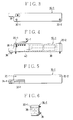
- Fig. 3, 4, 5, and 6 show a rear view, a plan view, a front view, and a left side view respectively of the auxiliary battery unit 16-1 shown in Fig. 1.
- a power source input terminal 36 is provided on the rear side of the auxiliary battery unit 16-1, and the screws 20-1 and 20-2 having screw holes in the heads are provided at two positions of the upper corners of the upper portion.
- the LED display section 30-1 using five LEDs is provided in the upper portion of the auxiliary battery unit 16-1.
- the LED switch 28-1 is provided near the LED display section 30-1.
- a printed circuit board 40 on which a circuit unit has been installed and a battery pack 38 are provided in the auxiliary battery unit 16-1 as shown by a broken line.
- eight NiCd cells are assembled in the battery pack 38 in a state in which they are connected in series. Since each NiCd cell has a nominal voltage of 1.2 V, the nominal output voltage of the battery pack 38 is equal to 9.6 V.
- the connector 24-1 connected to the cable 32-1 is enclosed in the concave portion at the left lower corner of the auxiliary battery unit 16-1.
- the screw 20-1 passes through the interior of the battery unit 16-1 and the screw portion is projected to the tip.
- Four cells are enclosed in the battery pack 38 when it is seen from the side, and as shown in Fig. 4, since those cells are provided in two lines, it is known that total eight cells are enclosed.
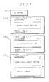
- Fig. 7 shows one example of the construction of a power source system embodying the invention which makes use of two auxiliary battery units (first embodiment).
- the personal computer 10 has a computer circuit 44 therein.
- a power source is supplied to the computer circuit 44 from a power source circuit section (further battery unit contained within the computer housing) 46.
- a main battery pack is enclosed in the power source circuit section 46.
- a current consumption of the computer circuit 44 is, for example, equal to or larger than 160 mA in the operating mode, and is equal to or less than 1 mA in the stand-by mode.
- An input connector 48 is provided for the power source circuit section 46.
- the auxiliary battery unit (first battery unit) 16-1 has an input connector 50-1, a battery circuit section 52-1, and an output connector 54-1.
- the battery unit (second battery unit) 16-2 also has an input connector 50-2, a battery circuit section 52-2, and an output connector 54-2.
- An AC adapter 42 receives, for example, a commercially available voltage of AC 100 V and outputs a specified DC voltage. In the embodiment, the AC adapter 42 generates DC 15 V and has a current capacity equal to 1.33 A.
- the AC adapter 42 is connected whilst the personal computer 10 and the auxiliary battery units 16-1 and 16-2 are charged. It is also possible to use the personal computer 10 by connecting the AC adapter 42 when it is used at a location where the AC power source is obtained. However, since the personal computer 10 is fundamentally used as a portable type, it will be appreciated that the AC adapter 42 is not normally connected to the computer 10 during use thereof,
- Fig. 8 shows one example of the circuit construction of the auxiliary battery unit which is used in the first embodiment.
- a noise filter 100 is provided to the output side of an input connector 50.
- a power source line from the noise filter 100 passes through a Zener diode 102, and a fuse 104 is connected to an analog switch 106 which operates as a first discharge switch.
- An output of the analog switch 106 is connected via a sense resister 108 (used to detect output current) to an output connector 52 through a noise filter 110.
- a resistor of 1 ⁇ is used as a sense resister 108.
- a battery pack 112 is formed by serially connecting eight NiCd cells 114. Since an output voltage at full charge of one NiCd cell 114 is nominally equal to 1.2 V, the battery pack 112 nominally generates 9.6 V in a state of full charge .
- a capacity of the battery pack 112 is equal to 1400 mA/h, for example.
- the battery pack 112 has therein a thermistor 164 to detect an internal temperature.
- a charging system for the battery pack 112 is as follows. An output line of the noise filter 100 connected to the input connector 50 is branched and connected to a high speed charging circuit 122. An output of the high speed charging circuit 122 passes through a Zener diode 124 and is connected to a plus side of the battery pack 112. In parallel with the high speed charging circuit 122, a serial circuit, or trickle resistor 126, and an analog switch 128 is connected. A resistor of 470 ⁇ is used as the trickle resistor 126.
- a discharging system from the battery pack 112 will now be described.
- the plus side of the battery pack 112 is connected to an analog switch 118 through a sense resistor 116 used to detect a discharge current.
- the analog switch 118 operates as a second discharge switch.
- a resistor of 1 ⁇ is used as a sense resistor 116.
- An output of the analog switch 118 is connected to a cathode side of the Zener diode 102 through a Zener diode 120. Due to this, both of the analog switches 118 and 106 must be turned on in order to discharge the battery pack 112.
- a charge control and a discharge control for the battery pack 112 are executed by a microprocessor 130.
- Regulators 134 and 142 are provided as a power source section to produce a power source voltage of the whole circuit including the microprocessor 130.
- a voltage on the equipment side of the fuse 104 is applied to the regulator 134 through a switching circuit 132 and a fuse 105.
- the switching circuit 132 is turned on when an input voltage exceeds, for example, 4 V, and supplies a power source voltage to the regulator 134.
- the regulator 134 converts the input voltage into a predetermined output constant voltage Vccl. For instance, 3.2 V is used as a power source voltage Vccl.
- a reference voltage generating circuit 136 generates a reference voltage Vcc2, for example, 1.235 V on the basis of the output voltage Vcc1 provided by the regulator 134. The reference voltage is used by the AD convertor to supply data to the microprocessor 130.
- the regulator 142 receives the input voltage when an analog switch 140 is turned on and generates a power source voltage Vcc3, for example, 3. 0 V which is supplied to the microprocessor 130.
- the analog switch 140 is turned on in response to a control signal E9 when the microprocessor 130 detects that an AC adaptor is connected to the input connector 50. Therefore, in the case where the AC adapter is not connected to the input connector 50, the analog switch 140 is turned off and the power source voltage Vcc3 from the regulator 142 is cut off.
- the power source voltage Vcc3 from the regulator 142 is mainly used as a power source voltage of a charging circuit system. Due to this, during discharge control when no AC adapter is connected, the regulator 142 is cut off, thereby preventing electric power consumption due to the charging circuit system.
- a resetting circuit 138 operates when the power source voltage Vccl from the regulator 134 is obtained and generates a power-on reset signal El to the microprocessor 130. In response to the power-on reset signal E1, the microprocessor 130 executes an initial reset.
- the microprocessor 130 has a charge control section 182, a discharge control section 184, and a display control section 186 which are realized by a program control.
- the charge control section 182 When the charge control section 182 detects the connection of the AC adapter, the charge control section 182 makes the high speed charging circuit 122 operative on the basis of a detection signal E3 (output current measure) produced by an output current detecting circuit 150 in this instance, thereby allowing the charging operation of the battery pack 112 to be executed.
- a detection signal E3 output current measure
- a check is first made to see if the AC adapter is connected to the input connector 50 or not on the basis of a voltage detection signal E2 obtained from a voltage divider arrangement comprising resistors 146 and 148 which form a voltage detecting circuit 144.
- An input voltage from the input connector 50 is equal to DC 15 V in the case where the AC adapter is connected, DC 9.6 V in the case where another auxiliary battery unit is connected, and DC 0V in the case in which neither the AC adapter nor any other auxiliary battery unit is connected. Therefore, the charge control section 182 of the microprocessor 130 can recognize the connection of the AC adapter by a voltage detection of DC 15 V on the basis of the voltage detection signal E2 from the voltage detecting circuit 144. When the connection of the AC adapter is detected, the charge control operation by the charge control section 182 is started. The charge control operation is executed according to the magnitude of the current detection signal E3 from the output current detecting circuit 150.
- the charging time of the battery pack 112 by high speed charging is, for example, 1.2 hours.
- the charge control section 182 stops the operation of the high speed charging circuit 122 and turns on the analog switch 128 and switches to the trickle charging by the trickle resistor 126.
- the trickle charging is executed while the personal computer is operating.
- the high speed charging circuit 122 and the analog switch 128 for trickle charging are controlled by control signals E12 and E13 from the microprocessor 130.
- the control signal E12 When the charge control section 182 detects the connection of the AC adapter, the control signal E12 is made active.
- the high speed charging circuit 122 operates by negative logic on the basis of the control signals E12 and E13. Therefore, upon the detection of the AC adapter, the control signal E12 is set to the low level.
- the high speed charging circuit 122 operates when both of the control signals E12 and E13 are set to the low level, thereby executing the charging at a high speed.
- the high speed charging circuit 122 has an NAND gate to which the control signals E12 and E13 are supplied, a transistor switch which is turned on/off by an output of the NAND gate, and a current limiting circuit to limit the charge current to a predetermined high speed charging current value in the ON state of the transistor switch.
- the analog switch 128 operates by positive logic.
- the control signal E13 changes from the low level to the high level. Due to this, the operation of the high speed charging circuit 122 is stopped, the analog switch 128 is turned on at the same time, and the trickle charging of the battery pack 112 via the trickle resistor 126 is started.
- the charge current is determined by a resistance value of 470 ⁇ of the trickle resistor 126 according to the voltage difference between the input voltage from the AC adapter and the present charging voltage of the battery pack 112.
- the charging operation of the charge control section 182 is stopped in any one of the following cases: namely, when a predetermined time, measured by a timer activated at the start of the charging, for example, 1.2 hours of the high speed charging elapses; when an abnormal temperature is detected by the thermistor 164 provided for the battery pack 112; and further, when the full charging is detected on the basis of a change in charging voltage of the battery pack 112.
- an AD converter 156 to detect a battery current
- an AD converter 158 to detect a temperature
- an AD converter 160 to detect a battery voltage
- an AD converter 162 to detect the presence or absence of the battery.
- the AD converter 156 to detect the battery current receives a voltage across the sense resistor 116 provided for the discharge circuit and converts the received voltage into a digital voltage detection signal E4 which is supplied to the microprocessor 130.
- the AD converter 158 to detect the temperature supplies a temperature detection signal E5,based on the thermistor 164 built into the battery pack 112,to the microprocessor 130.
- the AD converter 160 to detect the battery voltage supplies a voltage detection signal E6, obtained converting the charging voltage of the battery pack 112, to the microprocessor 130. Further, the AD converter 162 to detect the presence or absence of the battery supplies a detection signal E7 indicative of the presence or absence of the connection of the battery pack 112 to the microprocessor 130.
- a signal line which is pulled up by a resistor 166 to the power source voltage +Vcc1 passes into the battery pack 112 as shown by a broken line, and provides the microprocessor 130 with a detection signal E8 in the event of a leakage of the battery pack 112.
- a shorting current flows through the resistor 166 and the leak detection signal E8 drops to 0 V. Therefore, the microprocessor 130 can detect a short-circuit of the battery pack 112 by such a voltage drop.
- the display control section 186 provided in the microprocessor 130 executes a display control of the LED display section 30.
- Five LEDs 170, 172, 174, 176, and 178 are provided in the LED display section 30 and are driven by control signals E15, E16, E17, E18, and E19.
- the display control section 186 operates and drives the display section 30 when an LED switch 28 is in the ON position.
- the LED switch 28 is pulled up to the power source Vcc1 through a resistor 168.
- a switch signal E14 is at the high level because it is pulled up to the power source voltage Vcc1.
- the switch signal E14 is set to the low level, so that the display control section 186 operates.
- the LED 170 is lit up by the control signal E15 when the input of DC 15 V by the AC adapter is detected.
- the LEDs 172, 174, and 176 are sequentially lit up by the control signals E16 to E18 in accordance with the magnitude of the charging voltage of the battery pack 112. For example, the three LEDs 172, 174, and 176 are lit up when the battery pack 112 is fully charged, whereas just the two LEDS 174 and 176 are lit up when the voltage is low. Only Only the LED 176 is lit up when the voltage is even lower. Further, the LED 178 flickers in accordance with the control signal E19 when a decrease in the battery voltage is detected. Therefore, when the LED 178 flickers while the LED switch 28 is ON, it will be understood that it is necessary to charge.
- the microprocessor 130 operates using clocks of 1.8 MHz and 32 KHz from quartz oscillators 152 and 154 provided externally of the microprocessor. For example, a four bit microprocessor is used as a microprocessor 130.
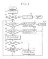
- FIG. 9 shows a processing operation by the microprocessor 130 provided in Fig. 8.
- step S1 When a power source voltage exceeding 4 V is supplied, the switching circuit 132 is turned on and supplies the power source voltage to the regulator 134.
- the microprocessor 130 executes an initialization in step S1. Subsequently, a check is made to see if the battery pack 112 is connected or not in step S2. If the battery pack 112 is not connected, an alarm is generated in step S8 and the processing routine is finished as an abnormal state.
- step S3 follows and a check is made if an AC adapter has been connected or not.
- step S9 follows.
- the analog switch 106 serving as a first discharge switch, is turned on and the analog switch 118, serving as a second discharge switch, is turned off.
- the processing routine advances to a charging process in step S10.
- the details of the charging process in step S10 are shown as a subroutine in Fig. 10.
- step S4 follows and a check is made to see if another auxiliary battery unit has been connected or not.
- the input detection voltage by the voltage detecting circuit 144 is equal to DC 9.6 V.
- step S11 the analog switch 106 serving as the first discharging switch is turned on in a manner similar to the case in step S9, the analog switch 118 serving as the second discharging switch is turned off, and the supplied voltage from the connected auxiliary battery unit, received via the input connector 50, is supplied directly to the output connector 52 by the analog switch 106 which is in the ON state.
- step S5 When another battery unit is not connected in step S4, namely when the input detection voltage is equal to 0 V, step S5 follows.
- the analog switches 118 and 106 (first and second discharging switches respectively) are each turned on. Due to this, a discharging circuit from the battery pack 112 to the output connector 52 is formed and a discharging state using the unit's own battery pack 112 is obtained.
- step S5 When the discharging state is established in step S5, a drop in the battery voltage is discriminated in step S6 and an overcurrent is detected in step S7.
- step S12 follows and the analog switch 118 (second discharging switch) is turned off and the discharging operation of the battery pack 112 is stopped.
- the analog switch 118 second discharging switch
- step S12 follows and the analog switch 118 (second discharging switch) is turned off and the discharging operation of the battery pack 112 is stopped.
- the analog switch 118 second discharging switch
- Fig. 10 shows details of the charging process shown in step S10 in Fig. 9 as a subroutine.
- the charging process in Fig. 10 is started.
- step S3 a check is made to see if the charging has been completed or not by discriminating whether the timer activated by the start of the charging has reached a set time, for example, 1.2 hours or not.
- step S4 a completion of the charging is judged on the basis of the battery voltage. If the battery pack 112 uses NiCd cells 114, the charging voltage increases during charging with the elapse of time and it starts to drop when it is fully charged. Therefore, in step S4, it is judged that the charging has been completed when the value of a negative time change ratio due to a decrease in charging voltage exceeds a predetermined threshold value.
- step S5 a check is made to see if the detection temperature measured by the thermistor 164 provided in the battery pack 112 is equal to or higher than a specified value or not. Since there is a fear that, when the charging of the battery pack 112 is suddenly executed the internal temperature rises and the NiCd cell itself is damaged, the charging is stopped when the detection temperature is equal to or higher than the specified value.
- step S6 follows and a charge stopping process to stop the operation of the high speed charging circuit 122 is executed. Such a high speed charging process is executed in a stand-by mode in which the personal computer 10 is not used.
- step S6 a trickle charging process is executed. That is, the operation of the high speed charging unit 122 is stopped and at the same time, the analog switch 128 is turned on.
- the charging current depends on the resistance value (470 ⁇ ) of the trickle resistor 126 and a voltage difference between the supply voltage of the AC adapter at that time and the charging voltage of the battery pack 112.
- a check is also made to see if there is any abnormality due to the completion of the charging by the battery voltage in step S4 or the increase in battery temperature in step S5.
- a charge stopping process is executed in step S6.
- Fig. 11 shows the power source circuit section 46 provided in the personal computer 10 shown in Fig. 7.
- the power source circuit section 46 which is provided in the personal computer is a circuit from which the analog switch 106 as a first discharge switch provided in the battery circuit section of the auxiliary battery unit shown in Fig. 8 is eliminated but otherwise the remaining circuit construction is substantially the same. Therefore, in Fig. 11, the same component elements as those shown in Fig. 8 are designated by substantially the same reference numerals with respect to the "unit” digit and the "tens" digit but the "hundreds" digit is changed from “1" to "2".
- the noise filter 100 provided subsequently to the input connector 50 in Fig. 8 is shown as a noise filter 200 in Fig. 11.
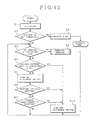
- Fig. 12 is a flowchart showing the processing operation of the power source circuit section provided in the personal computer in Fig. 11.
- the flowchart of Fig. 12 corresponds to the flowchart of Fig. 9 relating to the auxiliary battery unit.
- the processes in steps 9 to 11 in Fig. 9 are eliminated and the ON operations of the first and second discharge switches in step S5 is changed to the ON operation of a single discharge switch. That is, the power source circuit section in Fig. 11 provided in the personal computer executes the discharge control using only an analog switch 218 provided in the discharging line of the battery pack 212.
- the analog switch 218 is turned off and the discharging of the computer's own battery pack 212 is stopped.
- the analog switch 218 is turned on, thereby enabling discharging from the computer's own battery pack 212.
- Fig. 13 shows the charging process by the power source circuit section provided in the personal computer shown in step S9 in Fig. 12 as a subroutine.
- the charging process is substantially the same process as that in the case of the auxiliary battery unit shown in Fig. 10.
- the charging operation and discharging operation of the system as a whole when the two auxiliary battery units 16-1 and 16-2 are connected in such a series configuration to the personal computer 10 as shown in Fig. 7 will now be described.
- the charging operation is executed by connecting the AC adapter 42 to the last auxiliary battery unit 16-2.
- the AC adapter 42 generates DC 15 V
- the battery circuit sections 52-2 and 52-1 of the auxiliary battery units 16-1 and 16-2 detect the connection of the AC adapter 42 from their respective input voltages of DC 15 V
- the respective charging control sections of the units 16-1 and 16-2 are set into the operating mode.
- the power source circuit section 46 of the personal computer 10 also recognizes the connection of the AC adapter 42 from its input voltage of DC 15 V and sets its charging control section into the operating mode.
- the high speed charging is executed first to the battery pack 212 of the power source circuit section 46 provided in the personal computer 10 by the charging control of each of the power source circuit section 46 and the battery circuit sections 52-1 and 52-2.
- the current due to the high speed charging is detected by the auxiliary battery units 16-1 and 16-2, and since the current exceeds the threshold current Ith, the trickle charging state is obtained. That is, the high speed charging is started from the power source circuit section 46 of the personal computer 10.
- the output current flowing in the auxiliary battery units 16-1 and 16-2 becomes the stand-by current of the personal computer 10 again. Each of those units starts the charging operation again. However, the output current flowing upon commencement of charging in the auxiliary battery unit 16-1 located nearest to the personal computer 10 is detected by the other auxiliary battery unit 16-2 and the charging mode thereof is switched to trickle charging. Due to this, when the high speed charging of the personal computer 10 is completed, the high speed charging of the auxiliary battery unit 16-1 is started subsequently. When the high speed charging of the auxiliary battery unit 16-1 is finished, the charging mode is finally switched to the high speed charging of the auxiliary battery unit 16-2.
- the charging mode is switched from the high speed charging to the trickle charging at that time point. Therefore, each of the charging operations can be sequentially executed while using the personal computer 10.
- the discharge control in a state in which the AC adapter 42 is detached will now be described.
- the input voltage of the input connector 50-2 of the auxiliary battery unit 16-2 furthest from the computer is equal to 0V. Due to this, the battery circuit section 52-2 allows its unit's own battery pack to be discharged.
- the battery circuit section 52-1 detaches its unit's own battery pack and the battery voltage of 9.6 V from the auxiliary battery unit 16-2 is supplied directly to the personal computer 10.
- the power source circuit section 46 detaches the computer's own battery pack 212 and supplies 9.6 V, received from outside, directly to the computer circuit 44 as a power source voltage.
- the battery circuit section 52-1 commences discharging and connects its unit's own battery pack, thereby supplying DC 9.6 V to the personal computer 10.
- the power source circuit section 46 of the personal computer 10 is still in a state in which the discharging of the computer's own battery pack is prevented.
- the discharging operation of the power source circuit section 46 is executed, the computer's own battery pack is connected to the discharging line and the discharging to supply a power source to the computer circuit 44 is started.
- the discharging operation is executed sequentially, starting from the auxiliary battery unit 16-2 connected furthest in the series from the personal computer 10.
- the maximum value (n) of the auxiliary battery units which can be connected to the personal computer 10 is set to the maximum value (n) which satisfies the following equation since when the power source is lower than the necessary power source voltage, the personal computer 10 is stopped.
- V AC denotes an output voltage of the AC adapter
- V F denotes a drop voltage by the auxiliary battery unit
- Fig. 14 shows a second embodiment of the invention.
- only one auxiliary battery unit (the second battery unit) 16 is provided externally for the personal computer 10.
- the auxiliary battery unit 16 has the same structure as that of one of the auxiliary battery units shown in Fig. 1.
- Fig. 15 shows a system construction in the modified invention of Fig. 14.
- the personal computer 10 has the computer circuit 44, power source circuit section (first battery unit) 46, and input connector 48 in a manner similar to Fig. 7
- the auxiliary battery unit 16 has the input connector 50, battery circuit section 52, and output connector 54.
- the AC adapter 42 is connected to the input connector 50 of the auxiliary battery unit 16.
- the battery circuit section 52 of the auxiliary battery unit 16 has a circuit construction shown in Fig. 16.
- the analog switch 118 which was provided in the discharging line of the battery pack 112 in the auxiliary battery unit in the case where a plurality of auxiliary battery units are connected, is eliminated.
- the discharging control is executed only by the analog switch 106 provided between the input and output connectors 50 and 52. Since the other circuit construction is similar to that in the embodiment of Fig. 8, the same component elements are designated by the same reference numerals.
- a charge control section 382, a discharge control section 384, and a display control section 386 which are realized by a program control are provided for the microprocessor 130.
- each circuit has only the single analog switch 106 or the single analog switch 218, as the case may be, as a discharging switch, and the processes of the charge control sections 282 and 382 are almost the same although the positions of the analog switches 106 and 218 are different in the two circuits.
- Fig. 17 shows the processing operation in the auxiliary battery unit in Fig. 16.
- the processing operation itself is substantially the same as that of Fig. 12 except that the discharging switch in each of steps S5 and S10 is the analog switch 106 in the case of Fig. 16 rather than the analog switch 218 as in the case of Fig. 11.
- Fig. 18 in which the charging process in step S9 in Fig. 17 is shown as a subroutine, the process is almost the same as that shown in Fig. 13.
- the battery pack of the power source circuit section (first battery unit) 46 of the personal computer 10 is first charged and the battery pack of the battery circuit section 52 of the auxiliary battery unit (second battery unit) 16 is subsequently charged.
- the discharging operation is started from the battery pack of the auxiliary battery unit (second battery unit) 16 and when discharging of the auxiliary battery unit 16 is finished, the discharging mode is switched to the discharging from the battery unit of the power source circuit section (first battery unit) 46. That is, with respect to the charging and discharging as well, the charging and discharging operations are executed essentially in the same order as the first embodiment having a plurality of auxiliary battery units which can be connected externally as mentioned above.
- an embodiment of the present invention can provide a power source system of a portable information processing system using a battery which enables operation over long periods of time by connecting and fixing an auxiliary battery unit to the system main body.
Landscapes
- Engineering & Computer Science (AREA)
- Power Engineering (AREA)
- Theoretical Computer Science (AREA)
- Physics & Mathematics (AREA)
- General Engineering & Computer Science (AREA)
- General Physics & Mathematics (AREA)
- Business, Economics & Management (AREA)
- Emergency Management (AREA)
- Charge And Discharge Circuits For Batteries Or The Like (AREA)
- Secondary Cells (AREA)
- Power Sources (AREA)
Claims (30)
- Gerät, umfassend eine portable elektrische Vorrichtung (10) und jeweils erste und zweite Batterieeinheiten (16-1, 16-2; 16, 46), wobei jede Batterieeinheit eine oder mehrere wiederaufladbare Batterien (114; 114, 214) umfaßt, um eine elektrische Leistung an eine Schaltungsanordnung (44) der Vorrichtung zu liefern;dadurch gekennzeichnet, daß während eines solchen sequentiellen Ladens und einer solchen sequentiellen Leistungsversorgung die ersten und zweiten Batterieeinheiten in einer Serienanordnung zusammengeschaltet sind, in welcher der Eingang der ersten Batterieeinheit (16-1; 46) mit dem Ausgang der zweiten Batterieeinheit (16-2; 16) verbunden ist, wobei die Schaltungsanordnung (44) an der Ausgangsseite der ersten Batterieeinheit angeschlossen ist;wobei jede der Batterieeinheiten einen Eingang (50-1, 50-2; 50, 48) zum Empfangen einer elektrischen Leistung zum Laden ihrer einen oder ihrer mehreren Batterien sowie einen Ausgang (54-1, 54-2; 54, -) zum Liefern einer elektrischen Leistung von ihrer einen oder ihren mehreren Batterien aufweist; undwobei, wenn das Gerät im Einsatz ist, die Batterieeinheiten derart angeschlossen sind und gesteuert werden, daß wenn eine externe Leistungszuführquelle (42) an das Gerät angeschlossen ist, die erste Batterieeinheit (16-1; 46) zuerst geladen wird, und sodann die zweite Batterieeinheit (16-2; 16) geladen wird, und derart, daß wenn keine solche externe Leistungszuführquelle angeschlossen ist, die Schaltungsanordnung (44) zuerst durch die zweite Batterieeinheit mit Leistung versorgt wird, bis diese Einheit entladen ist, und dann durch die erste Batterieeinheit;
und daß jede der Batterieeinheiten Steuermittel (130; 130, 230) aufweist, welche zusammenwirken, um das sequentielle Laden zu bewerkstelligen, wenn eine solche externe Leistungszuführquelle an das Gerät angeschlossen ist, und die sequentielle Leistungsversorgung zu bewerkstelligen, wenn keine solche externe Leistungszuführquelle angeschlossen ist. - Gerät nach Anspruch 1, bei welchem die ersten und zweiten Batterieinheiten (16-1; 16-2) in jeweiligen Gehäusen außerhalb des Gehäuses dieser Vorrichtung (10) aufgenommen sind.
- Gerät nach Anspruch 2, bei welchem:die portable elektrische Vorrichtung (10) eine Informationsverarbeitungsvorrichtung ist, die einen Leistungsquellen-Eingangsanschluß (48) hat; undwenn die ersten und zweiten Batterieinheiten (16-1; 16-2) in der genannten Serienanordnung zusammengeschaltet sind, diese Einheiten körperlich mit dem Vorrichtungsgehäuse verbindbar sind und die erste Batterieeinheit (16-1) elektrisch mit dem genannten Leistungsquellen-Eingangsanschluß (48) verbunden ist.
- Gerät nach Anspruch 3, bei welchem in jeder dieser Batterieinheiten (16-1; 16-2) die eine oder die mehreren wiederaufladbaren Batterien aus einer Vielzahl von Batteriezellen (114) aufgebaut ist/sind, die in Reihe miteinander verbunden und in einer Batteriepackung (112) aufgenommen sind; undwobei jede der Batterieinheiten (16-1; 16-2) ferner umfaßt:einen Eingangsanschluß (50) welcher an einen Ausgangsanschluß (52) einer anderen Batterieeinheit oder einen Ausgangsanschluß (26) einer externen Leistungszuführquelle (42) anschließbar ist;einen Ausgangsanschluß (54), welcher an einen Eingangsanschluß (50) einer anderen solchen Batterieeinheit oder den Leistungsquellen-Eingangsanschluß (48) der Informationsverarbeitungsvorrichtung (50) anschließbar ist;Spannungsdetektiermittel (144) zum Detektieren einer Eingangsleistungsquellenspannung, welche an den Eingangsanschluß (52) angelegt wird;Stromdetektiermittel (150) zum Detektieren eines Ausgangsstroms, welcher durch den Ausgangsanschluß (52) fließt;erste Entladeschaltmittel (106) zum Ein-/Ausschalten der Zufuhr einer Leistung zu diesem Ausgangsanschluß (54);zweite Entladeschaltmittel (118) zum Ein-/Ausschalten der Zufuhr einer Leistung von der Batteriepackung (112) der Einheit;Ladeschaltmittel (122) zum Ein-/Ausschalten der Zufuhr einer Leistung von dem Eingangsanschluß (50) zu der Batteriepackung (112) der Einheit;Ladesteuerungsmittel (182), welche so betreibbar sind, daß sie den Anschluß einer solchen externen Leistungszuführquelle (42) detektieren, und zwar auf der Basis der Detektierung einer solchen Eingangsleistungsquellenspannung durch die Spannungsdetektiermittel (144), und nach Detektierung eines solchen Anschlusses die Ladeschaltmittel (122) veranlassen, die Zufuhr einer Leistung von dem Eingangsanschluß (50) zu der Batteriepackung (112) der Einheit einzuschalten, um ein Laden dieser Batteriepackung zu bewerkstelligen, unter der Voraussetzung, daß der Ausgangsstrom, welcher durch die Stromdetektiermittel (150) detektiert wird, gleich oder kleiner als ein vorgegebener Wert ist; undEntladesteuerungsmittel (184), die so betreibbar sind, daß sie, wenn der Anschluß einer solchen externen Leistungszuführquelle (42) oder einer anderen solchen Batterieeinheit auf der Basis einer Detektierung einer Eingangsleistungsquellenspannung durch die Spannungsdetektiermittel (144) detektiert wird, die ersten Entladeschaltmittel (106) veranlassen, die Zufuhr einer Leistung zu dem Ausgangsanschluß (52) einzuschalten, und auch die zweiten Entladeschaltmittel (118) veranlassen, die Zufuhr einer Leistung von der Batteriepackung (112) der Einheit abzuschalten, um so extern zugeführte Leistung von dem Eingangsanschluß (50) zu dem Ausgangsanschluß (52) zu leiten, und die außerdem so betreibbar sind, daß wenn, basierend auf der Nichtdetektierung einer Eingangsleistungsquellenspannung durch die Spannungsdetektiermittel (144) detektiert wird, daß keine solche externe Leistungszuführquelle und keine solche andere Batterieeinheit angeschlossen ist, sie die ersten und zweiten Entladeschaltmittel (106, 118) veranlassen, jeweils die Zufuhr einer Leistung zu dem Ausgangsanschluß (52) und die Zufuhr von Leistung von der Batteriepackung (112) der Einheit einzuschalten, um so intern gelieferte Leistung von dieser Batteriepackung zu dem Ausgangsanschluß (52) zu leiten.
- Gerät nach Anspruch 4, bei welchem die Entladesteuerungsmittel (184) die zweiten Entladeschaltmittel (118) veranlassen, die Zufuhr von Leistung von der Batteriepackung (112) der Einheit abzuschalten, wenn detektiert wird, daß der Entladestrom von dieser Batteriepackung größer als oder gleich einem vorgegebenen Überstromwert ist.
- Gerät nach Anspruch 4 oder 5, bei welchem die Entladesteuerungsmittel die ersten und zweiten Entladeschaltmittel (106, 118) veranlassen, jeweils die Zufuhr einer Leistung zu dem Ausgangsanschluß (52) bzw. die Zufuhr einer Leistung von der Batteriepackung (112) der Einheit abzuschalten, wenn detektiert wird, daß die Entladespannung dieser Batteriepackung gleich oder kleiner als eine spezifizierte Spannung ist.
- Gerät nach einem der Ansprüche 3 bis 6, bei welchem die Vorrichtung (10) auch eine weitere derartige Batterieeinheit (46) aufweist, die innerhalb des Vorrichtungsgehäuses aufgenommen ist, wobei der Eingang (48) dieser weiteren Batterieeinheit mit dem Ausgang (54-1) der Batterieeinheit (16-1) verbunden ist, wenn das Gerät im Einsatz ist, und wobei der Ausgang dieser weiteren Batterieeinheit mit der Schaltungsanordnung (44) verbunden ist, wobei die weitere Batterieeinheit (46) Steuerungsmittel (230) aufweist, die mit den Steuerungsmitteln (130) der ersten und zweiten Batterieinheiten (16-1, 16-2) zusammenarbeiten, wenn eine solche externe Leistungszuführquelle (42) an die Eingangsseite der zweiten externen Leistungszuführquelle (16-2) angeschlossen ist, um zu bewirken, daß während des sequentiellen Ladens die weitere Batterieeinheit (46) geladen wird, bevor die erste Batterieeinheit (16-1) geladen wird, und die auch zusammenwirken, wenn keine solche externe Leistungszuführquelle angeschlossen ist, um zu bewirken, daß während des sequentiellen Ladens die Schaltungsanordnung (44) durch diese weitere Batterieeinheit mit Leistung versorgt wird, nachdem die erste Batterieeinheit entladen worden ist.
- Gerät nach Anspruch 1, bei welchem die erste Batterieeinheit (46) innerhalb des Gehäuses dieser Vorrichtung (10) aufgenommen ist, und die zweite Batterieeinheit (16) in ihrem eigenen Gehäuse aufgenommen ist, welches körper; lich mit dem Vorrichtungsgehäuse verbunden werden kann, wenn das Gerät im Einsatz ist.
- Gerät nach Anspruch 8, bei welchem:die portable elektrische Vorrichtung (10) eine Informationsverarbeitungsvorrichtung ist, die einen Leistungsquellen-Eingangsanschluß (48) hat; undwenn die ersten und zweiten Batterieeinheiten (46, 16) in der genannten Serienanordnung miteinander verbunden sind, die zweite Batterieeinheit (16) elektrisch mit dem Leistungsquellen-Eingangsanschluß (48) verbunden wird.
- Gerät nach Anspruch 9, bei welchem in der zweiten Batterieeinheit (16) die eine oder die mehreren wiederaufladbaren Batterien aus einer Vielzahl von Batteriezellen (114) gebildet ist/sind, welche in Reihe geschaltet und in einer Batteriepackung (112) aufgenommen sind; unddie zweite Batterieeinheit (16) ferner umfaßt:einen Eingangsanschluß (50), mit welchem ein Ausgangsanschluß (26) einer solchen externen Leistungszuführquelle (42) verbindbar ist;einen Ausgangsanschluß (52), welcher mit dem Leistungsquellen-Eingangsanschluß (48) der portablen elektrischen Vorrichtung (10) verbindbar ist;Spannungsdetektiermittel (144) zum Detektieren einer Eingangsleiscungsquellenspannung, die an den Eingangsanschluß (50) angelegt ist;Stromdetektiermittel (150) zum Detektieren eines Ausgangsstroms, welcher durch den Ausgangsanschluß (52) fließt;Entladeschaltmittel (106) zum Ein-/Ausschalten der Zufuhr einer Leistung zu dem Ausgangsanschluß (52);Ladeschaltmittel (122) zum Ein-/Ausschalten der Zufuhr einer Leistung von dem Eingangsanschluß (50) zu der Batteriepackung (112) der Einheit;Ladesteuerungsmittel (382), die so betreibbar sind, daß sie den Anschluß einer derartigen externen Leistungszuführquelle (42) auf der Basis der Detektierung einer solchen Eingangsleistungsquellenspannung durch die Spannungsdetektiermittel (144) detektieren und nach der Detektierung eines solchen Anschlusses bewirken, daß die Ladeschaltmittel (122) die Zufuhr einer Leistung von dem Eingangsanschluß (50) zu der Batteriepackung (112) der Einheit einschalten, um so ein Laden dieser Batteriepackung zu bewerkstelligen, unter der Voraussetzung, daß der durch die Stromdetektiermittel (150) detektierte Ausgangsstrom gleich oder kleiner als ein vorgegebener Wert ist; undEntladesteuerungsmittel (384), die derart betreibbar sind, daß wenn der Anschluß einer solchen externen Leistungszuführquelle auf der Basis der Detektierung einer solchen Eingangsleistungsquellenspannung durch die Spannungsdetektiermittel (144) detektiert wird, sie bewirken, daß die Entladeschaltmittel (106) die Zufuhr einer Leistung zu dem Ausgangsanschluß (52) einschalten, um so eine extern zugeführte Leistung zu der portablen elektrischen Vorrichtung durchzuleiten, und die auch derart betreibbar sind, daß wenn auf der Basis der Nichtdetektierung einer solchen Eingangsleistungsquellenspannung durch die Spannungsdetektiermittel (144) detektiert wird, daß keine solche externe Leistungszuführquelle (42) angeschlossen ist, sie bewirken, daß die Entladeschaltmittel (106) die Zufuhr einer Leistung zu dem Ausgangsanschluß (52) einschalten, um so eine intern zur Verfügung gestellte Leistung von der Batteriepackung der Einheit zu der portablen elektrischen Vorrichtung (10) durchgeleitet wird.
- Gerät nach Anspruch 10, bei welchem die Entladesteuerungsmittel (384) bewirken, daß die Entladeschaltmittel (106) die Zufuhr einer Leistung zu dem Ausgangsanschluß (52) abschalten, wenn eine intern zur Verfügung gestellte Leistung durchgeleitet wird, falls detektiert wird, daß der Entladestrom der Batteriepackung (112) der Einheit größer als oder gleich einem vorgegebenen Überstromwert ist.
- Gerät nach Anspruch 10 oder 11, bei welchem die Entladesteuerungsmittel (384) bewirken, daß die Entladeschaltmittel (106) die Zufuhr einer Leistung zu dem Ausgangsanschluß (52) abschalten, falls detektiert wird, daß die Entladespannung der Batteriepackung der Einheit kleiner als oder gleich einer spezifizierten Spannung ist.
- Gerät nach einem der Ansprüche 4 bis 6 oder 10 bis 12, bei welchem die Ladeschaltmittel (122) umfassen:Hochgeschwindigkeits-Lademittel (122), die so betreibbar sind, daß sie einen Strom in der Nähe eines maximal zulässigen Ladestroms für die Batteriepackung (112) der Einheit liefern, um eine Ladung mit einer hohen Geschwindigkeit zu bewerkstelligen; undTrickle-Lademittel (126), die parallel zu den Hochgeschwindigkeits-Lademitteln (122) geschaltet sind, und die so betreibbar sind, daß sie einen Trickle-Ladestrom liefern, welcher aus einer Spannungsdifferenz zwischen der Eingangsleistungsquellenspannung und der Ladespannung der Batteriepackung (112) der Einheit und aus einem spezifizierten Widerstandswert bestimmt wird; undwobei die Ladesteuerungsmittel (182; 382) die Hochgeschwindigkeits-Lademittel (122) in Betrieb setzen, wenn der durch die Stromdetektiermittel (150) detektierte Ausgangsstrom gleich oder kleiner als ein vorgegebener Wert in einem Status ist, in welchem der Anschluß einer solchen externen Leistungszuführquelle detektiert wird, wodurch eine Hochgeschwindigkeitsladung bewerkstelligt wird, und wobei diese auch die Trickle-Lademittel (126) in Betrieb setzen, wenn der detektierte Ausgangsstrom diesen vorgegebenen Wert überschreitet, wodurch eine Trickle-Ladung bewerkstelligt wird.
- Gerät nach einem der Ansprüche 4 bis 6 oder 10 bis 13, bei welchem die Ladesteuerungsmittel (182; 382) so betreibbar sind, daß sie bewirken, daß die Ladeschaltmittel (122) die Zufuhr von Leistung von dem Eingangsanschluß (50) zu der Batteriepackung (112) der Einheit abschalten, um so den Ladevorgang zu stoppen, wenn ein Zeitgeber, welcher beim Start des Ladevorganges aktiviert wurde, anzeigt, daß eine vorgegebene Zeitspanne abgelaufen ist.
- Gerät nach einem der Ansprüche 4 bis 6 oder 10 bis 14, bei welchem die Ladesteuerungsmittel (182; 382) so betreibbar sind, daß sie bewirken, daß die Ladeschaltmittel (122) die Zufuhr von Leistung von dem Eingangsanschluß (50) zu der Batteriepackung (112) der Einheit abschalten, um so das Laden zu stoppen, wenn für diese Batteriepackung vorgesehene Temperaturdetektiermittel (164; 158) detektieren, daß die Batteriepackung eine vorgegebene Temperatur übersteigt.
- Gerät nach einem der Ansprüche 4 bis 6 oder 10 bis 15, bei welchem die Ladesteuerungsmittel (182; 382) so betreibbar sind, daß sie die Leistungsquellenspannung der Batteriepackung (112) der Einheit überwachen und, wenn ein Abfall der überwachten Spannung detektiert wird, nachdem diese Spannung in Verbindung mit dem Ladevorgang so weit angestiegen ist, daß sie eine Scheitelspannung überschreitet, die Ladesteuerungsmittel (182; 382) bewirken, daß die Ladeschaltmittel (122) die Zufuhr einer Leistung von dem Eingangsanschluß (50) zu der Batteriepackung (112) der Einheit abschalten, um so den Ladevorgang zu stoppen.
- Gerät nach einem der Ansprüche 3 bis 16, welches ferner Anzeigemittel (30) zum Anzeigen eines Status der Batterieeinheit umfaßt.
- Gerät nach Anspruch 17, bei welchem die Anzeigemittel (30) wenigstens anzeigen, ob eine solche Eingangsleistungsquellenspannung an den Eingangsanschluß angelegt ist, ferner einen Ladezustand und einen Zustand der Batteriespannung der Batteriepackung (112) der Einheit.
- Gerät nach Anspruch 17 oder 18, bei welchem die Anzeigemittel (30) Anzeigeschaltmittel (28) aufweisen, um die Anzeigemittel (30) von einem EIN-Status, in welchem solche Anzeigen von den Anzeigemitteln (30) erzeugt werden, in einen AUS-Status zu schalten, in welchem diese Anzeigen nicht erzeugt werden.
- Gerät nach Anspruch 7 oder 9 oder nach einem der Ansprüche 10 bis 19, wenn diese im Zusammenhang mit Anspruch 7 oder Anspruch 9 gelesen werden, wobei:in der in dem Vorrichtungsgehäuse aufgenommenen Batterieeinheit (46) die eine oder die mehreren wiederaufladbaren Batterien aus einer Vielzahl von Batteriezellen (214) aufgebaut ist/sind, die in Reihe geschaltet und in einer Batteriepackung (212) aufgenommen sind, und der Leistungsquellen-Eingangsanschluß (48) mit einem Ausgangsanschluß (52) einer anderen Batterieeinheit oder mit einem Ausgangsanschluß (26) einer externen Leistungszuführquelle (42) verbindbar ist; unddie in dem Vorrichtungsgehäuse aufgenommene Batterieeinheit (46) ferner umfaßt:Spannungsdetektiermittel (244) zum Detektieren einer an den Leistungsquellen-Eingangsanschluß (48) angelegten Eingangsspannung;Stromdetektiermittel (250) zum Detektieren eines Ausgangsstroms, welcher zu der Schaltungsanordnung (44) fließt;Entladeschaltmittel (218) zum Ein-/Ausschalten der Zufuhr einer Leistung von der Batteriepackung (212);Ladeschaltmittel (222) zum Ein-/Ausschalten der Zufuhr einer Leistung von dem Leistungsquellen-Eingangsanschluß (48) zu der Batteriepackung (212);Ladesteuerungsmittel (282), die so betreibbar sind, daß sie den Anschluß einer solchen externen Leistungszuführquelle (42) detektieren, und zwar auf der Basis der Detektierung einer solchen Eingangsspannung durch die Spannungsdetektiermittel (244), und daß sie nach Detektierung eines solchen Anschlusses bewirken, daß Ladeschaltmittel (222) die Zufuhr einer Leistung von dem Leistungsquellen-Eingangsanschluß (48) zu der Batteriepackung (212) der Vorrichtung einschalten, um so ein Laden dieser Batteriepackung zu bewerkstelligen, vorausgesetzt, daß der durch die Stromdetektiermittel (250) detektierte Ausgangsstrom gleich oder kleiner als ein vorgegebener Wert ist; undEntladesteuerungsmittel (284), die derart betreibbar sind, daß sie, wenn der Anschluß einer solchen externen Leistungszuführquelle (42) oder einer solchen Batterieeinheit (16) auf der Basis der Detektierung einer Eingangsspannung durch die Spannungsdetektiermittel (244) detektiert wird, bewirken, daß die Entladeschaltmittel (218) die Zufuhr einer Leistung von der Batteriepackung der Vorrichtung abschalten, und die auch derart betreibbar sind, daß wenn auf der Basis der Nichtdetektierung einer solchen Eingangsspannung detektiert wird, daß keine solche externe Leistungszuführquelle und keine solche Batterieeinheit an> geschlossen ist, sie bewirken, daß die Entladeschaltmittel (218) die Zufuhr einer Leistung von der Batteriepackung der Vorrichtung einschaltet, so daß die Schaltungsanordnung (44) mit Leistung von der Batteriepackung versorgt wird.
- Gerät nach Anspruch 20, bei welchem die Ladeschaltmittel (222) der portablen elektrischen Vorrichtung (10) umfassen:Hochgeschwindigkeits-Lademittel (222), die so betreibbar sind, daß sie einen Strom in der Nähe eines maximal zulässigen Ladestroms der Batteriepackung (212) der Vorrichtung liefern, um eine Ladung mit hoher Geschwindigkeit zu bewerkstelligen; undTrickle-Lademittel (226), welche parallel zu den Hochgeschwindigkeits-Lademitteln (222) angeschlossen und so betreibbar sind, daß sie der Batteriepackung (212) der Vorrichtung einen Trickle-Ladestrom zuführen, welcher durch eine Spannungsdifferenz zwischen der Eingangsleistungsquellenspannung und der Ladespannung dieser Batteriepackung (212) sowie durch einen spezifizierten Widerstandswert bestimmt wird;und wobei die Ladesteuerungsmittel (282) die Hochgeschwindigkeits-Lademittel (222) in Betrieb setzen, wenn der durch die Stromdetektiermittel (250) detektierte Ausgangsstrom gleich oder kleiner als ein vorgegebener Wert in einem Zustand ist, in welchem der Anschluß einer solchen externen Leistungszuführquelle (42) detektiert wird, wodurch das Hochgeschwindigkeitsladen bewerkstelligt wird, wobei diese auch die Trickle-Lademittel (226) in Betrieb setzen, wenn der detektierte Ausgangsstrom den vorgegebenen Wert überschreitet, wodurch ein Trickle-Ladevorgang bewerkstelligt wird
- Gerät nach Anspruch 20 oder 21, bei welchem die Ladesteuerungsmittel (282) so betreibbar sind, daß sie bewirken, daß die Ladeschaltmittel (222) die Zufuhr einer Leistung von dem Leistungsquellen-Eingangsanschluß (48) zu der Batteriepackung (212) der Vorrichtung abschalten, um so den Ladevorgang zu stoppen, wenn ein beim Start des Ladevorganges aktivierter Zeitgeber anzeigt, daß eine vorgegebene Zeitspanne abgelaufen ist.
- Gerät nach Anspruch 20, 21 oder 22, bei welchem die Ladesteuerungsmittel (282) so betreibbar sind, daß sie bewirken, daß die Ladeschaltmittel (222) die Zufuhr einer Leistung von dem Leistungsquellen-Eingangsanschluß (48) zu der Batteriepackung (212) der Vorrichtung abschalten, um so den Ladevorgang zu stoppen, wenn durch für diese Batteriepackung vorgesehene Temperaturdetektiermittel (264, 258) detektiert wird, daß die Batteriepackung eine vorgegebene Temperatur überschreitet.
- Gerät nach einem der Ansprüche 20 bis 23, bei welchem die Ladesteuerungsmittel (282) so betreibbar sind, daß sie die Leistungsquellenspannung der Batteriepackung (212) überwachen, und wenn ein Abfall bei der überwachten Spannung detektiert wird, nachdem diese Spannung in Verbindung mit dem Ladevorgang so weit angestiegen ist, daß sie eine Scheitelspannung überschreitet, diese Ladesteuerungsmittel (282) bewirken, daß die Entladeschaltmittel (222) die Zufuhr einer Leistung von dem Leistungsquellen-Eingangsanschluß (48) zu der Batteriepackung (212) der Vorrichtung abschalten, um so den Ladevorgang zu stoppen.
- Gerät nach einem der Ansprüche 20 bis 24, ferner umfassend Anzeigemittel (280) zum Anzeigen eines Zustandes der portablen elektrischen Vorrichtung (10).
- Gerät nach Anspruch 25, bei welchem die Anzeigemittel (280) wenigstens anzeigen, ob eine Eingangsspannung an den Eingangsanschluß (48) angelegt ist, ferner einen Ladezustand und einen Zustand der Batteriespannung der Batteriepackung (212) der Vorrichtung.
- Gerät nach Anspruch 25 oder 26, bei welchem die Anzeigemittel (280) Anzeigeschaltmittel (282) aufweisen, um die Anzeigemittel (280) von einem EIN-Zustand, in welchem solche Anzeigen durch die Anzeigemittel (280) erzeugt werden, in einen AUS-Zustand zu schalten, in welchem solche Anzeigen nicht erzeugt werden.
- Gerät nach einem der Ansprüche 20 bis 27, bei welchem die Entladesteuerungsmittel (284) bewirken, daß die Entladeschaltmittel (218) die Zufuhr einer Leistung von der Batteriepackung der Vorrichtung abschalten, wenn detektiert wird, daß der Entladestrom dieser Batteriepackung größer als oder gleich einem vorgegebenen Überstromwert ist.
- Gerät nach einem der Ansprüche 20 bis 28, bei welchem die Entladesteuerungsmittel (284) bewirken, daß die Entladeschaltmittel (218) die Zufuhr einer Leistung von der Batteriepackung der Vorrichtung zu dem Schaltkreis (44) abschalten, wenn detektiert wird, daß die Entladespannung dieser Batteriepackung gleich oder kleiner als eine spezifizierte Spannung ist.
- Gerät nach einem der vorangehenden Ansprüche, ferner umfassend eine solche externe Leistungszuführquelle (42), wobei die externe Leistungszuführquelle AC-Adaptermittel zum Umwandeln einer AC-Leistungsquelle in eine DC-Leistungsquelle umfaßt.
Priority Applications (2)
| Application Number | Priority Date | Filing Date | Title |
|---|---|---|---|
| EP02000245A EP1209794B1 (de) | 1993-01-13 | 1994-01-13 | Stromversorgungsgeräte für tragbare elektrische Geräte |
| EP98113822A EP0881740B1 (de) | 1993-01-13 | 1994-01-13 | Stromversorgungsgeräte für tragbare elektrische Geräte |
Applications Claiming Priority (2)
| Application Number | Priority Date | Filing Date | Title |
|---|---|---|---|
| JP3943/93 | 1993-01-13 | ||
| JP5003943A JP2928431B2 (ja) | 1993-01-13 | 1993-01-13 | 補助バッテリ装置および充放電制御方法 |
Related Child Applications (1)
| Application Number | Title | Priority Date | Filing Date |
|---|---|---|---|
| EP98113822A Division EP0881740B1 (de) | 1993-01-13 | 1994-01-13 | Stromversorgungsgeräte für tragbare elektrische Geräte |
Publications (3)
| Publication Number | Publication Date |
|---|---|
| EP0607041A2 EP0607041A2 (de) | 1994-07-20 |
| EP0607041A3 EP0607041A3 (en) | 1995-09-06 |
| EP0607041B1 true EP0607041B1 (de) | 1999-03-31 |
Family
ID=11571210
Family Applications (3)
| Application Number | Title | Priority Date | Filing Date |
|---|---|---|---|
| EP94300234A Expired - Lifetime EP0607041B1 (de) | 1993-01-13 | 1994-01-13 | Stromversorgungsgeräte für tragbare elektrische Geräte |
| EP98113822A Expired - Lifetime EP0881740B1 (de) | 1993-01-13 | 1994-01-13 | Stromversorgungsgeräte für tragbare elektrische Geräte |
| EP02000245A Expired - Lifetime EP1209794B1 (de) | 1993-01-13 | 1994-01-13 | Stromversorgungsgeräte für tragbare elektrische Geräte |
Family Applications After (2)
| Application Number | Title | Priority Date | Filing Date |
|---|---|---|---|
| EP98113822A Expired - Lifetime EP0881740B1 (de) | 1993-01-13 | 1994-01-13 | Stromversorgungsgeräte für tragbare elektrische Geräte |
| EP02000245A Expired - Lifetime EP1209794B1 (de) | 1993-01-13 | 1994-01-13 | Stromversorgungsgeräte für tragbare elektrische Geräte |
Country Status (5)
| Country | Link |
|---|---|
| US (1) | US5563493A (de) |
| EP (3) | EP0607041B1 (de) |
| JP (1) | JP2928431B2 (de) |
| KR (1) | KR970006393B1 (de) |
| DE (3) | DE69434460T2 (de) |
Cited By (1)
| Publication number | Priority date | Publication date | Assignee | Title |
|---|---|---|---|---|
| RU2215355C1 (ru) * | 2002-11-22 | 2003-10-27 | Бахарев Владислав Сергеевич | Установка бесперебойного электроснабжения железнодорожной автоматики |
Families Citing this family (107)
| Publication number | Priority date | Publication date | Assignee | Title |
|---|---|---|---|---|
| US5661634A (en) * | 1993-11-09 | 1997-08-26 | Fujitsu Limited | Information processing system using portable terminal unit and data communication adapter therefor |
| US6274950B1 (en) | 1994-03-03 | 2001-08-14 | American Power Conversion | Battery communication system |
| US5633573A (en) * | 1994-11-10 | 1997-05-27 | Duracell, Inc. | Battery pack having a processor controlled battery operating system |
| JP3699498B2 (ja) * | 1994-12-26 | 2005-09-28 | ヤマハ発動機株式会社 | 2次電池と充電器の接続判定方法 |
| JP2986059B2 (ja) * | 1995-03-08 | 1999-12-06 | インターナショナル・ビジネス・マシーンズ・コーポレイション | バッテリ充電装置 |
| US5857148A (en) * | 1995-06-13 | 1999-01-05 | Motorola, Inc. | Portable electronic device and method for coupling power thereto |
| JP3228097B2 (ja) * | 1995-10-19 | 2001-11-12 | 株式会社日立製作所 | 充電システム及び電気自動車 |
| US5860015A (en) * | 1995-12-14 | 1999-01-12 | Gateway 2000, Inc. | Detachable palm rest with backup battery |
| US5717937A (en) * | 1996-03-04 | 1998-02-10 | Compaq Computer Corporation | Circuit for selecting and designating a master battery pack in a computer system |
| US5862392A (en) * | 1996-09-27 | 1999-01-19 | Energy Research Corporation | Battery incorporated into computer carrying case |
| JP3368163B2 (ja) * | 1996-12-18 | 2003-01-20 | インターナショナル・ビジネス・マシーンズ・コーポレーション | 電子機器用電源装置及び電子機器 |
| RU2125331C1 (ru) * | 1997-01-23 | 1999-01-20 | 16 Центральный научно-исследовательский испытательный институт Министерства обороны Российской Федерации | Автономная система электроснабжения передвижных объектов |
| US5982145A (en) * | 1997-04-08 | 1999-11-09 | Sony Chemicals Corporation | Battery pack unit, control method therefor, electronic equipment driven by power supplied from the same battery pack unit, and recording medium on which program for controlling the same battery pack unit is recorded |
| KR100259263B1 (ko) * | 1997-05-21 | 2000-06-15 | 윤종용 | 휴대용 컴퓨터 시스템의 배터리 충전회로 및 그 충전방법 |
| JP3410002B2 (ja) * | 1997-09-02 | 2003-05-26 | 富士電機株式会社 | 通信制御用集積回路及び通信制御システム |
| JPH11103532A (ja) * | 1997-09-29 | 1999-04-13 | Mitsubishi Electric Corp | バッテリ充電放電制御回路 |
| KR100290988B1 (ko) * | 1997-12-29 | 2001-06-01 | 윤종용 | 멀티유니트배터리팩및이멀티유니트배터리팩을사용하는시스템 |
| KR20000001400A (ko) * | 1998-06-11 | 2000-01-15 | 윤종용 | 휴대용 전자 장치의 전원 공급 시스템 |
| KR20000008583A (ko) * | 1998-07-14 | 2000-02-07 | 윤종용 | 휴대용 전자 시스템의 전원 공급 장치 |
| JP3737287B2 (ja) * | 1998-09-14 | 2006-01-18 | 富士通株式会社 | 機能拡張装置、部品ユニット及び電子機器 |
| US6664792B1 (en) * | 1998-09-29 | 2003-12-16 | Intel Corporation | Method and apparatus for battery power pre-check at system power-on |
| JP2000148310A (ja) * | 1998-11-04 | 2000-05-26 | Nec Yonezawa Ltd | 携帯用情報機器の選択型電源供給システム |
| US7301313B1 (en) * | 1999-03-23 | 2007-11-27 | Intel Corporation | Multiple voltage regulators for use with a single load |
| KR20010049026A (ko) * | 1999-11-30 | 2001-06-15 | 서평원 | 무선전화기의 배터리 회복 장치 및 그 방법 |
| US6344733B1 (en) * | 2000-01-31 | 2002-02-05 | Snap-On Technologies, Inc. | Portable jump-starting battery pack with charge monitoring system |
| JP4647747B2 (ja) * | 2000-06-08 | 2011-03-09 | 富士通セミコンダクター株式会社 | Dc−dcコンバータ及びdc−dcコンバータ用半導体集積回路装置 |
| US6586850B1 (en) * | 2000-07-05 | 2003-07-01 | Koninklijke Philips Electronics N.V. | Device with multiple, concurrently-installed power molecules and method for controlling same |
| KR100595718B1 (ko) * | 2000-07-28 | 2006-07-03 | 엘지전자 주식회사 | 휴대용 컴퓨터 시스템의 2차 배터리 연결장치 및 방법 |
| JP4978900B2 (ja) * | 2001-03-06 | 2012-07-18 | 株式会社加藤製作所 | 携帯電話機用充電電池 |
| US6424119B1 (en) | 2001-04-19 | 2002-07-23 | American Power Conversion | Multiple energy storage device controller |
| TW522589B (en) * | 2001-10-05 | 2003-03-01 | High Tech Comp Corp | Portable electronic system equipped with backup battery device |
| US7193393B1 (en) * | 2001-10-26 | 2007-03-20 | Payne James C | Approach for charging multiple batteries |
| JP3690665B2 (ja) * | 2001-10-30 | 2005-08-31 | インターナショナル・ビジネス・マシーンズ・コーポレーション | 電気機器、コンピュータ装置、および電力供給方法 |
| US6983212B2 (en) * | 2001-11-27 | 2006-01-03 | American Power Conversion Corporation | Battery management system and method |
| CA2437551A1 (en) * | 2001-12-06 | 2003-06-19 | Kimball International, Inc. | Mobile wireless data and electrical power unit |
| JP4208586B2 (ja) * | 2003-01-24 | 2009-01-14 | キヤノン株式会社 | 充電装置及びその充電制御方法 |
| JP3990990B2 (ja) | 2003-01-24 | 2007-10-17 | キヤノン株式会社 | 充電装置、電子機器、充電装置における電池残量表示制御方法、電子機器における電池残量検出方法 |
| US20040252114A1 (en) * | 2003-06-11 | 2004-12-16 | Steve Lin | Power supply system for flat panel display and method for the same |
| JP4276157B2 (ja) * | 2003-10-09 | 2009-06-10 | 三星エスディアイ株式会社 | プラズマディスプレイパネル及びその駆動方法 |
| US7737658B2 (en) * | 2003-10-27 | 2010-06-15 | Sony Corporation | Battery packs having a charging mode and a discharging mode |
| US7446433B2 (en) * | 2004-01-23 | 2008-11-04 | American Power Conversion Corporation | Methods and apparatus for providing uninterruptible power |
| US7612472B2 (en) * | 2004-01-23 | 2009-11-03 | American Power Conversion Corporation | Method and apparatus for monitoring energy storage devices |
| US7379305B2 (en) | 2004-01-23 | 2008-05-27 | American Power Conversion Corporation | Modular UPS |
| FR2868220B1 (fr) * | 2004-03-23 | 2008-02-15 | Thales Sa | Procede et dispositif d'alimentation electrique d'un equipement |
| JP2004350498A (ja) * | 2004-07-26 | 2004-12-09 | Hitachi Koki Co Ltd | 充電機能付き直流電源装置 |
| US7737580B2 (en) * | 2004-08-31 | 2010-06-15 | American Power Conversion Corporation | Method and apparatus for providing uninterruptible power |
| TWI286212B (en) * | 2004-11-03 | 2007-09-01 | Mediatek Inc | Battery detecting system |
| US7436151B2 (en) | 2004-12-23 | 2008-10-14 | Dell Products L.P. | Systems and methods for detecting charge switching element failure in a battery system |
| US7518341B2 (en) | 2004-12-23 | 2009-04-14 | Dell Product L.P. | Method for verifying smart battery failures by measuring input charging voltage and associated systems |
| GB2440065B (en) * | 2004-12-23 | 2008-07-30 | Dell Products Lp | Method for verifying smart battery failures by measuring inputcharging voltage and associated systems |
| US8026698B2 (en) * | 2006-02-09 | 2011-09-27 | Scheucher Karl F | Scalable intelligent power supply system and method |
| US7990102B2 (en) * | 2006-02-09 | 2011-08-02 | Karl Frederick Scheucher | Cordless power supply |
| US8860377B2 (en) | 2006-02-09 | 2014-10-14 | Karl F. Scheucher | Scalable intelligent power supply system and method |
| US8131145B2 (en) | 2006-02-09 | 2012-03-06 | Karl Frederick Scheucher | Lightweight cordless security camera |
| US20070210750A1 (en) * | 2006-03-08 | 2007-09-13 | Samsung Electronics Co., Ltd. | Power supply device and power supplying method for power supply device |
| US7679326B2 (en) * | 2006-04-13 | 2010-03-16 | Hewlett-Packard Development Company, L.P. | Computer with multiple removable battery packs |
| JP4618561B2 (ja) * | 2006-04-28 | 2011-01-26 | 日立工機株式会社 | 電池の充電装置 |
| USD632649S1 (en) | 2006-09-29 | 2011-02-15 | Karl F. Scheucher | Cordless power supply |
| CA2873314C (en) * | 2007-01-12 | 2018-02-27 | Koehler-Bright Star, Inc. | Battery pack for miner's cap lamp with charging and discharging control module |
| US8084154B2 (en) | 2007-02-08 | 2011-12-27 | Karl Frederick Scheucher | Battery pack safety and thermal management apparatus and method |
| US20080203970A1 (en) * | 2007-02-27 | 2008-08-28 | Phison Electronics Corp. | Battery-powered apparatus for portable system |
| US7952328B2 (en) * | 2007-04-12 | 2011-05-31 | Hewlett-Packard Development Company, L.P. | Multi-battery charging system and method |
| JP5559040B2 (ja) | 2007-05-15 | 2014-07-23 | シュナイダー エレクトリック アイティー コーポレーション | 設備の電力及び冷却を管理するための方法及びシステム |
| US8179102B2 (en) * | 2007-06-20 | 2012-05-15 | Motorola Mobility, Inc. | Devices, systems, and methods for priority charging of a group of electronic devices |
| US20090146607A1 (en) * | 2007-12-06 | 2009-06-11 | Tai-Her Yang | Serial stage power supply combination for emergency auxiliary charging apparatus |
| US8362747B2 (en) * | 2008-09-10 | 2013-01-29 | Intel Mobile Communications GmbH | Method of powering a mobile device |
| JP5085505B2 (ja) * | 2008-10-22 | 2012-11-28 | レノボ・シンガポール・プライベート・リミテッド | 携帯情報処理装置、その電力制御方法、およびコンピュータが実行可能なプログラム |
| US9711868B2 (en) * | 2009-01-30 | 2017-07-18 | Karl Frederick Scheucher | In-building-communication apparatus and method |
| US8472881B2 (en) * | 2009-03-31 | 2013-06-25 | Karl Frederick Scheucher | Communication system apparatus and method |
| JP5535517B2 (ja) * | 2009-04-30 | 2014-07-02 | 勝行 戸津 | キャパシタ電源装置を使用する電動工具の駆動方法 |
| US8115457B2 (en) | 2009-07-31 | 2012-02-14 | Power Integrations, Inc. | Method and apparatus for implementing a power converter input terminal voltage discharge circuit |
| WO2011033558A1 (ja) * | 2009-09-16 | 2011-03-24 | Necエナジーデバイス株式会社 | 2次電池パックシステム |
| CN202997003U (zh) * | 2009-12-04 | 2013-06-12 | 三洋电机株式会社 | 蓄电单元、发电系统及充放电系统 |
| WO2012036086A1 (ja) * | 2010-09-14 | 2012-03-22 | ソニー株式会社 | 蓄電ユニット群、充電器、電子機器、電動車両、蓄電ユニット群の充電方法及び放電方法、電力供給・受給方法、並びに、蓄電ユニット群における充放電ルート決定方法 |
| JP5659649B2 (ja) * | 2010-09-15 | 2015-01-28 | 住友電気工業株式会社 | 直流電源装置及び電力貯蔵システム |
| JP5786330B2 (ja) * | 2010-12-24 | 2015-09-30 | ソニー株式会社 | 放電制御装置及び放電制御方法 |
| CN102759950A (zh) * | 2011-04-28 | 2012-10-31 | 鸿富锦精密工业(深圳)有限公司 | 笔记本电脑 |
| JP5613135B2 (ja) * | 2011-10-31 | 2014-10-22 | レノボ・シンガポール・プライベート・リミテッド | 携帯端末装置の電池ユニットおよび電力の供給方法 |
| AU2011384046A1 (en) | 2011-12-22 | 2014-07-17 | Schneider Electric It Corporation | Analysis of effect of transient events on temperature in a data center |
| JP5867195B2 (ja) * | 2012-03-13 | 2016-02-24 | 日産自動車株式会社 | 二次電池の充電装置および二次電池の充電方法 |
| JP5921366B2 (ja) * | 2012-07-02 | 2016-05-24 | 株式会社やまびこ | 蓄電機の充電方法 |
| US9641009B2 (en) * | 2012-08-20 | 2017-05-02 | Nissan Motor Co., Ltd. | Charging device for secondary battery and charging method for secondary battery |
| US9252617B2 (en) * | 2012-12-17 | 2016-02-02 | Lenovo (Singapore) Pte. Ltd. | Battery cycling and management |
| JP5672356B2 (ja) * | 2012-12-21 | 2015-02-18 | 株式会社デンソー | 充電ケーブル装置 |
| CN103580297B (zh) * | 2013-01-10 | 2015-11-18 | 无锡知谷网络科技有限公司 | 移动设备及其充电方法 |
| KR102052724B1 (ko) * | 2013-04-15 | 2019-12-05 | 삼성전자주식회사 | 침수 여부 결정 방법 및 그 전자 장치 |
| TW201447543A (zh) * | 2013-06-05 | 2014-12-16 | Codetek Technology Co Ltd | 行動電源組合裝置 |
| KR20150000020A (ko) | 2013-06-19 | 2015-01-02 | 삼성전자주식회사 | 충전 기기 및 그 동작 방법 |
| US10300806B2 (en) * | 2013-10-09 | 2019-05-28 | Ford Global Technologies, Llc | Vehicle and method for controlling a battery in a vehicle |
| EP2869427B1 (de) * | 2013-10-31 | 2019-04-17 | ResMed Paris SAS | Vorrichtung zur behandlung einer beatmungsstörung mit einem stromquellenanschluss |
| TWI505600B (zh) * | 2014-01-24 | 2015-10-21 | 致伸科技股份有限公司 | 充電控制電路 |
| JP6054906B2 (ja) * | 2014-04-17 | 2016-12-27 | レノボ・シンガポール・プライベート・リミテッド | 電子機器、そのバッテリ制御方法、及びコンピュータが実行可能なプログラム |
| US10637264B2 (en) * | 2014-09-24 | 2020-04-28 | Powertec Solutions International Llc | Portable switching power supply with attachable battery pack and enclosure |
| JP6124852B2 (ja) * | 2014-09-24 | 2017-05-10 | レノボ・シンガポール・プライベート・リミテッド | 携帯型情報処理装置、そのバッテリ制御方法、及びコンピュータが実行可能なプログラム |
| CN105572593B (zh) * | 2014-10-11 | 2019-12-13 | 中兴通讯股份有限公司 | 一种电池在位检测的装置、方法和充电系统 |
| US9723743B2 (en) * | 2015-10-19 | 2017-08-01 | San Diego Gas & Electric Company | Electrical service interface system |
| US10177680B2 (en) | 2015-10-19 | 2019-01-08 | San Diego Gas & Electric Company | Electrical service interface system |
| US9515496B1 (en) * | 2016-03-21 | 2016-12-06 | Hangzhou Chic Intelligent Technology Co., Ltd | Battery management system for human-machine interaction vehicles |
| JP6970874B2 (ja) * | 2016-02-22 | 2021-11-24 | パナソニックIpマネジメント株式会社 | 電子機器 |
| JP6787214B2 (ja) | 2017-03-27 | 2020-11-18 | ブラザー工業株式会社 | 充電器及び充電制御方法 |
| US11218009B2 (en) * | 2018-04-18 | 2022-01-04 | Milwaukee Electric Tool Corporation | Tool circuitry for series-type connected battery packs |
| JP6522843B1 (ja) * | 2018-10-09 | 2019-05-29 | 株式会社アイ・ディー・エクス | バッテリ充電システムおよびその制御方法 |
| JP6640968B2 (ja) * | 2018-12-10 | 2020-02-05 | Necプラットフォームズ株式会社 | 充電制御システム |
| US11095141B1 (en) * | 2019-01-30 | 2021-08-17 | Glow Energy Group Corp. | Battery charge controller and related systems and methods |
| RU2762032C1 (ru) * | 2020-09-22 | 2021-12-14 | Акционерное общество "Научно-производственная фирма "СИГМА" | Автономная система электроснабжения модульной конструкции |
| CN223928102U (zh) * | 2021-11-23 | 2026-02-17 | 米沃奇电动工具公司 | 便携式电力供应器 |
| TW202329580A (zh) * | 2022-01-06 | 2023-07-16 | 精英電腦股份有限公司 | 堆疊式電源供應系統 |
Family Cites Families (10)
| Publication number | Priority date | Publication date | Assignee | Title |
|---|---|---|---|---|
| DE3404564A1 (de) * | 1984-02-09 | 1985-08-14 | Hans Kurt Dr.-Ing. 6233 Kelkheim Köthe | Schaltungsanordnung zur optimalen nutzung von ueberschussenergie mit hilfe von elektrochemischen akkumulatoren |
| US5162817A (en) * | 1989-01-28 | 1992-11-10 | Canon Kabushiki Kaisha | Ink jet with residual ink detection that compensates for different ink properties |
| US5028806A (en) * | 1989-04-14 | 1991-07-02 | Dell Corporate Services Corporation | Battery replacement system for battery-powered digital data handling devices |
| KR930008260B1 (ko) * | 1989-09-29 | 1993-08-27 | 가부시기가이샤 도시바 | 휴대용 컴퓨터를 위한 지능 전원 시스템 |
| GB2242794B (en) * | 1990-04-05 | 1994-08-03 | Technophone Ltd | Battery charging apparatus |
| EP0463593A3 (en) * | 1990-06-25 | 1992-08-05 | Kabushiki Kaisha Toshiba | Portable computer powered by rechargeable batteries |
| JPH0773413B2 (ja) * | 1990-07-31 | 1995-08-02 | 三洋電機株式会社 | 外部バッテリ用アダプタ及びバッテリシステム |
| US5264777A (en) * | 1991-07-24 | 1993-11-23 | Ample Power Company | System for isolating commonly charged batteries |
| US5162720A (en) * | 1991-10-15 | 1992-11-10 | Lambert Gordon K | Vehicle electrical system |
| US5420493A (en) * | 1992-06-30 | 1995-05-30 | Apple Computer, Inc. | Power supply and battery charger |
-
1993
- 1993-01-13 JP JP5003943A patent/JP2928431B2/ja not_active Expired - Lifetime
- 1993-12-30 US US08/175,723 patent/US5563493A/en not_active Expired - Lifetime
-
1994
- 1994-01-11 KR KR1019940000354A patent/KR970006393B1/ko not_active Expired - Fee Related
- 1994-01-13 EP EP94300234A patent/EP0607041B1/de not_active Expired - Lifetime
- 1994-01-13 DE DE69434460T patent/DE69434460T2/de not_active Expired - Fee Related
- 1994-01-13 DE DE69434815T patent/DE69434815T2/de not_active Expired - Fee Related
- 1994-01-13 EP EP98113822A patent/EP0881740B1/de not_active Expired - Lifetime
- 1994-01-13 EP EP02000245A patent/EP1209794B1/de not_active Expired - Lifetime
- 1994-01-13 DE DE69417458T patent/DE69417458T2/de not_active Expired - Fee Related
Cited By (1)
| Publication number | Priority date | Publication date | Assignee | Title |
|---|---|---|---|---|
| RU2215355C1 (ru) * | 2002-11-22 | 2003-10-27 | Бахарев Владислав Сергеевич | Установка бесперебойного электроснабжения железнодорожной автоматики |
Also Published As
| Publication number | Publication date |
|---|---|
| DE69434460T2 (de) | 2006-02-16 |
| JPH06217464A (ja) | 1994-08-05 |
| EP1209794A3 (de) | 2003-06-25 |
| KR940018716A (ko) | 1994-08-18 |
| EP0607041A2 (de) | 1994-07-20 |
| EP0881740B1 (de) | 2005-08-17 |
| EP0607041A3 (en) | 1995-09-06 |
| DE69434815D1 (de) | 2006-09-14 |
| EP0881740A2 (de) | 1998-12-02 |
| EP0881740A3 (de) | 2000-12-27 |
| DE69434460D1 (de) | 2005-09-22 |
| DE69417458D1 (de) | 1999-05-06 |
| DE69434815T2 (de) | 2006-11-30 |
| EP1209794B1 (de) | 2006-08-02 |
| EP1209794A2 (de) | 2002-05-29 |
| JP2928431B2 (ja) | 1999-08-03 |
| DE69417458T2 (de) | 1999-07-22 |
| KR970006393B1 (ko) | 1997-04-28 |
| US5563493A (en) | 1996-10-08 |
Similar Documents
| Publication | Publication Date | Title |
|---|---|---|
| EP0607041B1 (de) | Stromversorgungsgeräte für tragbare elektrische Geräte | |
| US20110163723A1 (en) | Battery pack and method of battery pack power management | |
| US5349668A (en) | Battery operated computer having improved battery monitor and cell reversal protection circuit | |
| US6362597B2 (en) | Power distribution in a portable device | |
| US6714016B2 (en) | Method for displaying information concerning power consumption and electronic device | |
| EP0736828A2 (de) | Batteriebetriebenes elektronisches Gerät und Verfahren zur Steuerung der Stromversorgung im Gerät | |
| US5625237A (en) | Remove power source device having improved capacity indication capability, and an electronic device using the removable power source device | |
| US8854007B2 (en) | Protection circuit for battery pack | |
| US20100146307A1 (en) | Power Hub | |
| US6163132A (en) | Battery charging status indicator apparatus | |
| US7211907B2 (en) | Programmable power control unit | |
| JP2001045670A (ja) | バッテリパック | |
| KR102167429B1 (ko) | 에너지 저장 장치의 과방전 방지 및 재기동 장치 및 방법 | |
| JPH09308131A (ja) | 電子装置とその制御方法 | |
| KR20010026261A (ko) | 배터리의 누설전류보상방법 | |
| JP2001339867A (ja) | 電池とモーターを内蔵する電気機器 | |
| JP2780699B2 (ja) | パーソナルコンピュータのバッテリ制御方法と電源制御回路 | |
| JPH077858A (ja) | 電子機器 | |
| JPH04317526A (ja) | 電池ユニツトおよび電子機器 | |
| JPH07147166A (ja) | 2次電池のメモリ効果防止方法 | |
| KR101070629B1 (ko) | 휴대용 전자기기의 전원공급시스템 및 그 제어방법 | |
| JP2001143766A (ja) | 充電装置、充放電制御方法及び記憶媒体 | |
| JPH042978A (ja) | 電池の残量表示機能を有する電池パック | |
| JPH04160419A (ja) | 携帯端末装置 | |
| JPH09289742A (ja) | 電子装置とその制御方法 |
Legal Events
| Date | Code | Title | Description |
|---|---|---|---|
| PUAI | Public reference made under article 153(3) epc to a published international application that has entered the european phase |
Free format text: ORIGINAL CODE: 0009012 |
|
| AK | Designated contracting states |
Kind code of ref document: A2 Designated state(s): DE |
|
| PUAL | Search report despatched |
Free format text: ORIGINAL CODE: 0009013 |
|
| AK | Designated contracting states |
Kind code of ref document: A3 Designated state(s): DE FR GB |
|
| 17P | Request for examination filed |
Effective date: 19951026 |
|
| 17Q | First examination report despatched |
Effective date: 19970214 |
|
| GRAG | Despatch of communication of intention to grant |
Free format text: ORIGINAL CODE: EPIDOS AGRA |
|
| GRAG | Despatch of communication of intention to grant |
Free format text: ORIGINAL CODE: EPIDOS AGRA |
|
| GRAG | Despatch of communication of intention to grant |
Free format text: ORIGINAL CODE: EPIDOS AGRA |
|
| GRAH | Despatch of communication of intention to grant a patent |
Free format text: ORIGINAL CODE: EPIDOS IGRA |
|
| GRAH | Despatch of communication of intention to grant a patent |
Free format text: ORIGINAL CODE: EPIDOS IGRA |
|
| RBV | Designated contracting states (corrected) |
Designated state(s): DE |
|
| GRAA | (expected) grant |
Free format text: ORIGINAL CODE: 0009210 |
|
| AK | Designated contracting states |
Kind code of ref document: B1 Designated state(s): DE |
|
| REF | Corresponds to: |
Ref document number: 69417458 Country of ref document: DE Date of ref document: 19990506 |
|
| PLBE | No opposition filed within time limit |
Free format text: ORIGINAL CODE: 0009261 |
|
| STAA | Information on the status of an ep patent application or granted ep patent |
Free format text: STATUS: NO OPPOSITION FILED WITHIN TIME LIMIT |
|
| 26N | No opposition filed | ||
| PGFP | Annual fee paid to national office [announced via postgrant information from national office to epo] |
Ref country code: DE Payment date: 20090108 Year of fee payment: 16 |
|
| PG25 | Lapsed in a contracting state [announced via postgrant information from national office to epo] |
Ref country code: DE Free format text: LAPSE BECAUSE OF NON-PAYMENT OF DUE FEES Effective date: 20100803 |