EP0607246B1 - Alimentation electrique auxiliaire stabilisee - Google Patents
Alimentation electrique auxiliaire stabilisee Download PDFInfo
- Publication number
- EP0607246B1 EP0607246B1 EP92921197A EP92921197A EP0607246B1 EP 0607246 B1 EP0607246 B1 EP 0607246B1 EP 92921197 A EP92921197 A EP 92921197A EP 92921197 A EP92921197 A EP 92921197A EP 0607246 B1 EP0607246 B1 EP 0607246B1
- Authority
- EP
- European Patent Office
- Prior art keywords
- voltage
- power supply
- auxiliary
- output
- regulated power
- Prior art date
- Legal status (The legal status is an assumption and is not a legal conclusion. Google has not performed a legal analysis and makes no representation as to the accuracy of the status listed.)
- Expired - Lifetime
Links
Images



Classifications
-
- G—PHYSICS
- G06—COMPUTING OR CALCULATING; COUNTING
- G06F—ELECTRIC DIGITAL DATA PROCESSING
- G06F1/00—Details not covered by groups G06F3/00 - G06F13/00 and G06F21/00
- G06F1/26—Power supply means, e.g. regulation thereof
- G06F1/30—Means for acting in the event of power-supply failure or interruption, e.g. power-supply fluctuations
- G06F1/305—Means for acting in the event of power-supply failure or interruption, e.g. power-supply fluctuations in the event of power-supply fluctuations
-
- G—PHYSICS
- G05—CONTROLLING; REGULATING
- G05F—SYSTEMS FOR REGULATING ELECTRIC OR MAGNETIC VARIABLES
- G05F1/00—Automatic systems in which deviations of an electric quantity from one or more predetermined values are detected at the output of the system and fed back to a device within the system to restore the detected quantity to its predetermined value or values, i.e. retroactive systems
- G05F1/10—Regulating voltage or current
- G05F1/46—Regulating voltage or current wherein the variable actually regulated by the final control device is DC
- G05F1/56—Regulating voltage or current wherein the variable actually regulated by the final control device is DC using semiconductor devices in series with the load as final control devices
-
- H—ELECTRICITY
- H02—GENERATION; CONVERSION OR DISTRIBUTION OF ELECTRIC POWER
- H02M—APPARATUS FOR CONVERSION BETWEEN AC AND AC, BETWEEN AC AND DC, OR BETWEEN DC AND DC, AND FOR USE WITH MAINS OR SIMILAR POWER SUPPLY SYSTEMS; CONVERSION OF DC OR AC INPUT POWER INTO SURGE OUTPUT POWER; CONTROL OR REGULATION THEREOF
- H02M3/00—Conversion of DC power input into DC power output
- H02M3/22—Conversion of DC power input into DC power output with intermediate conversion into AC
- H02M3/24—Conversion of DC power input into DC power output with intermediate conversion into AC by static converters
- H02M3/28—Conversion of DC power input into DC power output with intermediate conversion into AC by static converters using discharge tubes with control electrode or semiconductor devices with control electrode to produce the intermediate AC
- H02M3/325—Conversion of DC power input into DC power output with intermediate conversion into AC by static converters using discharge tubes with control electrode or semiconductor devices with control electrode to produce the intermediate AC using devices of a triode or a transistor type requiring continuous application of a control signal
- H02M3/335—Conversion of DC power input into DC power output with intermediate conversion into AC by static converters using discharge tubes with control electrode or semiconductor devices with control electrode to produce the intermediate AC using devices of a triode or a transistor type requiring continuous application of a control signal using semiconductor devices only
- H02M3/33561—Conversion of DC power input into DC power output with intermediate conversion into AC by static converters using discharge tubes with control electrode or semiconductor devices with control electrode to produce the intermediate AC using devices of a triode or a transistor type requiring continuous application of a control signal using semiconductor devices only having more than one ouput with independent control
Definitions
- This invention relates to a regulated auxiliary power supply for use with personal computers and similar electronic equipment.
- a personal computer includes a regulated power supply which produces the required supply voltage, normally 5 Volts, for the various loads within the computer. Such power supplies generally provide a 12 Volt output in addition.
- the power supply is regulated to maintain a constant voltage as the current requirements vary. A problem arises when it is desired to drive a remote terminal from the same power supply or to include circuitry in the computer that must be powered redundantly from two separate systems. If the supply is regulated according to the requirements of the main computer components, in the first case the voltage drop along the supply lead reduces the voltage at the auxiliary output, and in the second case the voltage at the auxiliary output is reduced by the series isolation diodes required to separate the two systems.
- GB 2,233,172 describes a power supply for generating 5V or 12V for various loads within a computer and which can be used to charge a rechargeable battery, but the problem of voltage drop along the supply is not addressed.
- EP 438,655 deals with the problem of voltage drop, but for a reference voltage that drops along a bus coupled to a reference voltage generating circuit, and the solution proposed is not applicable to the situation described above.
- An object of the invention is to provide a regulated power supply capable of overcoming the aforementioned disadvantages.
- an auxiliary regulated power supply for use in a system having a main load directly connected to a main regulated power supply and an auxiliary load connected to the main regulated power supply by a line in which a voltage drop occurs, said auxiliary regulated power supply comprising a pair of input terminals for connection to said line, a pair of terminals for connection to a secondary voltage source, a pair of output terminals for connection to the auxiliary load, means for sensing the voltage at the output terminals, and means for boosting the output voltage at said output terminals from said voltage source as necessary to maintain said output voltage at a level appropriate for said auxiliary load.
- the means for boosting the output voltage is a forward converter.
- a push-pull converter may advantageously be employed.
- the invention also provides a method of providing an auxiliary voltage regulated output for connection to an auxiliary load that is connected to a main regulated power supply over a line in which a voltage drop occurs, comprising sensing the voltage across said auxiliary load, and boosting said voltage from a secondary voltage source as necessary to maintain it at the appropriate level.
- personal computer 1 comprises an internal regulated power supply 2, which drives a CPU 3 and other standard components (not shown).
- the computer 1 is connected to a remote terminal 4, which is driven by the same power supply 2 as the computer 1 over a lossy line 5, which causes a voltage drop across it.
- a problem is that if the power supply is properly regulated for the CPU of the computer 1, the voltage drop across line 5 connecting the computer 1 to the terminal 4 causes the voltage applied to the remote terminal to become too low and consequently no longer regulated.
- Figure 2 shows an alternative situation where a load 6 is required to be driven redundantly from separate power supplies 2 of computers 1, 1′, which are respectively connected to the load 6 through isolation diodes 7, 8.
- the voltage drop across the isolation diodes causes the voltage to be applied to the load 6 to become too low.
- an input voltage is applied across a series combination of an inductance 9 and high speed switch 10, which in practice is a transistor.
- the inductance 9 acts as a current source.
- the current in inductance 9 ramps up when transistor 10 is on and ramps down through the diode 11 when the transistor 10 is off. A steady voltage appears at the output.
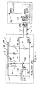
- a conventional regulated main power supply circuit 13 supplies a regulated 5 Volt output at a main output defined by terminals 13a, 13b and in addition a 12 Volt output at terminal 13c.
- Power supply circuit 13 may be, for example, the main power supply of a personal computer.
- the voltage drop can be caused by isolation diodes, as shown in Figure 2.
- the isolation diode can be placed as shown in Figure 4 as 99 in broken lines.
- Power supply 13 is connected to input terminals 14, 15 of the auxiliary circuit by a line 5 including loss resistance 5′, which causes a voltage drop in the line.
- auxiliary regulated output defined by terminals 14, 17 is derived from the voltage appearing at terminals 14, 15.
- Terminal 15 is connected to terminal 17 through inductance 18′ forming a secondary winding of transformer 18, diode 19 and inductance 20, and also parallel diode 22.
- Smoothing capacitor 30 is connected across the input teriminals 14, 15.
- Primary winding 18 ⁇ of transformer 18 is connected to a 12 volt supply, which can conveniently be provided by the main power supply 13 through terminal 13c, in series with switch 21, which in practice is a high speed transistor driven by a control circuit 32 in dependence on the voltage at output terminal 17.
- Control circuit 32 is a pulse width modulated control circuit, for example having a UC3845 integrated circuit manufactured by Unitrode, or Motorola.
- the duty cycle of the transistor 21 is adjusted to maintain the desired 5 volts at output terminal 17 regardless of the current drawn by the auxiliary load (not shown) across terminals 14, 17.
- Each ampere of current drawn on the 5 volt input generates one ampere of 5 volt output current, with the extra power being taken from the 12 volt source. This extra power also overcomes any losses in the convertor itself.
- the transformer 18 also includes a clamp winding 18′′′ in series with a diode 25 to limit the voltage developed across switch 21.
- High speed switch 21 causes a current to be induced in inductance 20, which ramps up when the transistor 21 is on and down when it is off.
- Capacitor 23 acts as a smoothing capacitor to minimize ripple.
- the net effect of the circuit is to produce a regulated 5 Volt output at terminals 14, 17, which consists of the voltage appearing at terminals 14, 15 boosted as necessary by extra voltage derived from the 12 Volt supply.
- Figure 5 shows an arrangement including a push-pull buck converter circuit. Similar components have similar reference numerals to Figure 4.
- the primary and secondary windings of transformer 18′ are split into half-windings 18′a, 18′b, and 18 ⁇ a, 18 ⁇ c respectively, which are provided in a push-pull arrangement.
- Terminal 15 is connected to the common point of windings 18′a and 18′b, and the common point of half-windings 18 ⁇ a, 18 ⁇ b is connected to the 12V supply.
- Diode 25 is replaced by a switch 31 controlled by the control circuit 32.
- the push-pull arrangement is useful at higher currents.
Landscapes
- Engineering & Computer Science (AREA)
- Physics & Mathematics (AREA)
- General Physics & Mathematics (AREA)
- Theoretical Computer Science (AREA)
- Power Engineering (AREA)
- General Engineering & Computer Science (AREA)
- Electromagnetism (AREA)
- Radar, Positioning & Navigation (AREA)
- Automation & Control Theory (AREA)
- Dc-Dc Converters (AREA)
- Stand-By Power Supply Arrangements (AREA)
- Direct Current Feeding And Distribution (AREA)
Abstract
Claims (11)
- Alimentation électrique auxiliaire stabilisée destinée à un système ayant une charge principale directement connectée à une alimentation électrique principale stabilisée et une charge auxiliaire connectée à l'alimentation électrique principale stabilisée par une ligne dans laquelle intervient une chute de tension, caractérisée en ce que ladite alimentation électrique auxiliaire stabilisée comprend une paire de bornes d'entrée (14, 15) pour la connexion à ladite ligne, une paire de bornes (figures 4 et 5) pour la connexion à une source de tension secondaire, une paire de bornes de sortie (14, 17) pour la connexion à la charge auxiliaire, des moyens (32) pour mesurer la tension aux bornes de sortie, et des moyens (21, 18) pour survolter la tension de sortie auxdites bornes de sortie à partir de ladite source de tension dans la mesure nécessaire pour maintenir ladite tension de sortie à un niveau approprié pour ladite charge auxiliaire.
- Alimentation électrique stabilisée selon la revendication 1, caractérisée en ce que lesdits moyens de survoltage (18, 19, 21, 22) comprennent un convertisseur dévolteur (18, 19, 21, 22) pour ajouter une tension à la tension apparaissant entre lesdites bornes d'entrée (14, 15) afin de maintenir ladite tension de sortie au niveau approprié.
- Alimentation électrique stabilisée selon la revendication 2, caractérisée en ce que ledit convertisseur dévolteur (18, 19, 21, 22) est un convertisseur direct.
- Alimentation électrique stabilisée selon la revendication 2, caractérisée en ce que ledit convertisseur dévolteur (18, 19, 21, 22) est un convertisseur push-pull.
- Alimentation électrique stabilisée selon la revendication 2, caractérisée en ce que le convertisseur dévolteur (18, 19, 21, 22) comprend un transistor interrupteur (21) connecté en série avec une inductance branchée (18a, 18b) sur ladite source de tension, des moyens de diode (19, 22) et des moyens de capacité (23) pour fournir une tension additionnelle lissée à ladite sortie auxiliaire, ledit transistor interrupteur (21) étant commandé en fonction des besoins de survoltage de la tension de sortie.
- Alimentation électrique stabilisée selon la revendication 3, caractérisée en ce que l'inductance (18a, 18b) est comprise dans un transformateur (18) couplant la source de tension à la sortie auxiliaire.
- Alimentation électrique stabilisée selon l'une quelconque des revendications 1 à 4, caractérisée en ce que ledit niveau approprié est le même que la tension stabilisée fournie par l'alimentation électrique principale.
- Système comprenant une alimentation électrique principale (13) et une alimentation électrique auxiliaire selon l'une quelconque des revendications 1 à 7, caractérisé en ce que ladite source de tension est constituée par ladite alimentation électrique principale (13).
- Procédé pour fournir une sortie de tension stabilisée auxiliaire destinée à être connectée à une charge auxiliaire qui est connectée à une alimentation électrique stabilisée principale par une ligne dans laquelle intervient une chute de tension caractérisé en ce que ledit procédé comprend les étapes consistant à mesurer la tension aux bornes de ladite charge auxiliaire et à survolter ladite tension à partir d'une source de tension secondaire dans la mesure nécessaire pour la maintenir au niveau approprié.
- Procédé selon la revendication 9, caractérisé en ce que la tension est survoltée au moyen d'un convertisseur dévolteur (18, 19, 21, 22).
- Procédé selon la revendication 9, caractérisé en ce que la source de tension secondaire est fournie par une sortie additionnelle sur l'alimentation électrique principale (13).
Applications Claiming Priority (3)
| Application Number | Priority Date | Filing Date | Title |
|---|---|---|---|
| CA2053382 | 1991-10-11 | ||
| CA002053382A CA2053382C (fr) | 1991-10-11 | 1991-10-11 | Survolteur |
| PCT/CA1992/000443 WO1993007674A1 (fr) | 1991-10-11 | 1992-10-09 | Alimentation electrique auxiliaire stabilisee |
Publications (2)
| Publication Number | Publication Date |
|---|---|
| EP0607246A1 EP0607246A1 (fr) | 1994-07-27 |
| EP0607246B1 true EP0607246B1 (fr) | 1995-12-13 |
Family
ID=4148552
Family Applications (1)
| Application Number | Title | Priority Date | Filing Date |
|---|---|---|---|
| EP92921197A Expired - Lifetime EP0607246B1 (fr) | 1991-10-11 | 1992-10-09 | Alimentation electrique auxiliaire stabilisee |
Country Status (6)
| Country | Link |
|---|---|
| US (1) | US5502634A (fr) |
| EP (1) | EP0607246B1 (fr) |
| CA (1) | CA2053382C (fr) |
| DE (1) | DE69206813T2 (fr) |
| MX (1) | MX9205877A (fr) |
| WO (1) | WO1993007674A1 (fr) |
Families Citing this family (5)
| Publication number | Priority date | Publication date | Assignee | Title |
|---|---|---|---|---|
| DK16393D0 (da) * | 1993-02-12 | 1993-02-12 | Silcon Power Electronics As | Noedstroemsanlaeg |
| US5640059A (en) * | 1995-12-21 | 1997-06-17 | Reltec Corporation | Power supply system including thermal current limiting protection |
| US5912513A (en) * | 1997-11-14 | 1999-06-15 | Lucent Technologies, Inc. | Method and apparatus for reducing power dissipation in DC termination circuit |
| US6172432B1 (en) | 1999-06-18 | 2001-01-09 | Gen-Tran Corporation | Automatic transfer switch |
| TWI312611B (en) * | 2006-06-30 | 2009-07-21 | Innolux Display Corp | Power supply circuit |
Family Cites Families (10)
| Publication number | Priority date | Publication date | Assignee | Title |
|---|---|---|---|---|
| US3414802A (en) * | 1966-04-18 | 1968-12-03 | Bell Telephone Labor Inc | Stacked series regulator |
| US3657478A (en) * | 1969-12-30 | 1972-04-18 | Honeywell Inc | Interconnection bus system |
| NL7212971A (fr) * | 1972-09-26 | 1974-03-28 | ||
| US4276590A (en) * | 1979-04-30 | 1981-06-30 | The Perkin-Elmer Corporation | Current sharing modular power system |
| US4760375A (en) * | 1983-10-28 | 1988-07-26 | Josef Stecker | Data transmission cable |
| US4885718A (en) * | 1987-09-11 | 1989-12-05 | Cybex Corporation | Extended communications link for keyboard and display units remotely located from a computer |
| US5029280A (en) * | 1988-04-13 | 1991-07-02 | National Semiconductor Corp. | ECL circuit for resistance and temperature bus drop compensation |
| GB8910193D0 (en) * | 1989-05-04 | 1989-06-21 | Astec Int Ltd | Improvements in power supplies |
| US5036452A (en) * | 1989-12-28 | 1991-07-30 | At&T Bell Laboratories | Current sharing control with limited output voltage range for paralleled power converters |
| JP2930445B2 (ja) * | 1991-04-23 | 1999-08-03 | 富士通株式会社 | 電源ユニット |
-
1991
- 1991-10-11 CA CA002053382A patent/CA2053382C/fr not_active Expired - Lifetime
-
1992
- 1992-10-09 EP EP92921197A patent/EP0607246B1/fr not_active Expired - Lifetime
- 1992-10-09 US US08/211,618 patent/US5502634A/en not_active Expired - Lifetime
- 1992-10-09 DE DE69206813T patent/DE69206813T2/de not_active Expired - Fee Related
- 1992-10-09 WO PCT/CA1992/000443 patent/WO1993007674A1/fr not_active Ceased
- 1992-10-13 MX MX9205877A patent/MX9205877A/es not_active IP Right Cessation
Also Published As
| Publication number | Publication date |
|---|---|
| CA2053382A1 (fr) | 1993-04-12 |
| DE69206813D1 (de) | 1996-01-25 |
| MX9205877A (es) | 1993-05-01 |
| DE69206813T2 (de) | 1996-08-08 |
| CA2053382C (fr) | 2000-04-18 |
| US5502634A (en) | 1996-03-26 |
| WO1993007674A1 (fr) | 1993-04-15 |
| EP0607246A1 (fr) | 1994-07-27 |
Similar Documents
| Publication | Publication Date | Title |
|---|---|---|
| US6756772B2 (en) | Dual-output direct current voltage converter | |
| US6989655B2 (en) | Engine generator | |
| US6426884B1 (en) | Reducing reverse currents in a synchronous rectifier circuit | |
| EP0804827B1 (fr) | Alimentation electrique sans coupure | |
| EP1415386B1 (fr) | Regulateur a decoupage simple et efficace pour charges transitoires rapides | |
| US5414610A (en) | Universal power converter with single, shared power transformation circuit | |
| EP1033804A2 (fr) | Sysème électrique à double tension pour véhicules avec convertisseur courant continu - courant continu sub-résonant | |
| US4502104A (en) | Bootstrapped AC-DC power converter | |
| US4833582A (en) | Frequency converter circuit including a single-ended blocking frequency converter | |
| EP0129181A2 (fr) | Convertisseur continu-continu | |
| US6841897B2 (en) | Input power sharing | |
| CA2053382C (fr) | Survolteur | |
| CN114144966A (zh) | 具有保持电路和浪涌控制电路的转换器 | |
| JP3238833B2 (ja) | 電源回路 | |
| US5442536A (en) | Low-loss power supply device comprising a DC/DC converter | |
| US9823677B2 (en) | Power converter | |
| US4754387A (en) | Start-up circuit for a switch mode power supply | |
| JPH067743B2 (ja) | 電源装置 | |
| JPH07264866A (ja) | Ac−dcコンバータ | |
| GB2243961A (en) | DC-DC Power supply circuit | |
| US6628533B2 (en) | DC-to-DC converter providing high current and low voltage | |
| US6515877B1 (en) | DC-to-DC converter providing high current and low voltage | |
| JPH1039936A (ja) | 多出力電源供給装置 | |
| EP4622078A1 (fr) | Convertisseur elevateur-septique integre pour alimentation basse tension | |
| JPH0326796Y2 (fr) |
Legal Events
| Date | Code | Title | Description |
|---|---|---|---|
| PUAI | Public reference made under article 153(3) epc to a published international application that has entered the european phase |
Free format text: ORIGINAL CODE: 0009012 |
|
| 17P | Request for examination filed |
Effective date: 19940411 |
|
| AK | Designated contracting states |
Kind code of ref document: A1 Designated state(s): DE GB IT |
|
| 17Q | First examination report despatched |
Effective date: 19940826 |
|
| GRAA | (expected) grant |
Free format text: ORIGINAL CODE: 0009210 |
|
| AK | Designated contracting states |
Kind code of ref document: B1 Designated state(s): DE GB IT |
|
| REF | Corresponds to: |
Ref document number: 69206813 Country of ref document: DE Date of ref document: 19960125 |
|
| ITF | It: translation for a ep patent filed | ||
| PGFP | Annual fee paid to national office [announced via postgrant information from national office to epo] |
Ref country code: DE Payment date: 19961018 Year of fee payment: 5 |
|
| PLBE | No opposition filed within time limit |
Free format text: ORIGINAL CODE: 0009261 |
|
| STAA | Information on the status of an ep patent application or granted ep patent |
Free format text: STATUS: NO OPPOSITION FILED WITHIN TIME LIMIT |
|
| 26N | No opposition filed | ||
| PG25 | Lapsed in a contracting state [announced via postgrant information from national office to epo] |
Ref country code: DE Free format text: LAPSE BECAUSE OF NON-PAYMENT OF DUE FEES Effective date: 19980701 |
|
| REG | Reference to a national code |
Ref country code: GB Ref legal event code: 732E |
|
| REG | Reference to a national code |
Ref country code: GB Ref legal event code: IF02 |
|
| PG25 | Lapsed in a contracting state [announced via postgrant information from national office to epo] |
Ref country code: IT Free format text: LAPSE BECAUSE OF NON-PAYMENT OF DUE FEES Effective date: 20051009 |
|
| REG | Reference to a national code |
Ref country code: GB Ref legal event code: 732E |
|
| PGFP | Annual fee paid to national office [announced via postgrant information from national office to epo] |
Ref country code: GB Payment date: 20101006 Year of fee payment: 19 |
|
| REG | Reference to a national code |
Ref country code: GB Ref legal event code: PE20 Expiry date: 20121008 |
|
| PG25 | Lapsed in a contracting state [announced via postgrant information from national office to epo] |
Ref country code: GB Free format text: LAPSE BECAUSE OF EXPIRATION OF PROTECTION Effective date: 20121008 |