EP0607436B1 - Dispositif de decrassage - Google Patents
Dispositif de decrassage Download PDFInfo
- Publication number
- EP0607436B1 EP0607436B1 EP92917808A EP92917808A EP0607436B1 EP 0607436 B1 EP0607436 B1 EP 0607436B1 EP 92917808 A EP92917808 A EP 92917808A EP 92917808 A EP92917808 A EP 92917808A EP 0607436 B1 EP0607436 B1 EP 0607436B1
- Authority
- EP
- European Patent Office
- Prior art keywords
- trough
- scum
- weir member
- barrage
- surface level
- Prior art date
- Legal status (The legal status is an assumption and is not a legal conclusion. Google has not performed a legal analysis and makes no representation as to the accuracy of the status listed.)
- Expired - Lifetime
Links
Images



Classifications
-
- B—PERFORMING OPERATIONS; TRANSPORTING
- B01—PHYSICAL OR CHEMICAL PROCESSES OR APPARATUS IN GENERAL
- B01D—SEPARATION
- B01D21/00—Separation of suspended solid particles from liquids by sedimentation
- B01D21/24—Feed or discharge mechanisms for settling tanks
- B01D21/2433—Discharge mechanisms for floating particles
-
- B—PERFORMING OPERATIONS; TRANSPORTING
- B01—PHYSICAL OR CHEMICAL PROCESSES OR APPARATUS IN GENERAL
- B01D—SEPARATION
- B01D21/00—Separation of suspended solid particles from liquids by sedimentation
- B01D21/18—Construction of the scrapers or the driving mechanisms for settling tanks
-
- B—PERFORMING OPERATIONS; TRANSPORTING
- B01—PHYSICAL OR CHEMICAL PROCESSES OR APPARATUS IN GENERAL
- B01D—SEPARATION
- B01D21/00—Separation of suspended solid particles from liquids by sedimentation
- B01D21/18—Construction of the scrapers or the driving mechanisms for settling tanks
- B01D21/20—Driving mechanisms
Definitions
- the present invention generally relates to a scum removal apparatus for efficiently removing scum floating in a sewage treatment pool and, more particularly, to a simplified scum removal apparatus of a type effective to efficiently remove scum by the utilization of a driving power generated by a movable member installed in the sewage treatment pool and without relying on a dedicated driving power.
- a scum removal apparatus according to the preamble of claim 1 is for example known from JP-U3 115 093.
- FIGs. 6 and 7 of the accompanying drawings illustrate such a scum removal apparatus known from JP-U3 115 093 and suggested by the inventor of the present invention.
- a generally rectangular sewage settling pool is provided with a plurality of, for example, four, sprocket shafts 200 extending in a widthwise direction of the sewage settling pool, a pair of sprocket wheels 201 mounted on each of the sprocket shafts 200 and generally endless, left-hand and right-hand chains trained around the sprocket wheels 201 on the sprocket shafts 200.
- some or all of the flights 203 secured to the chains 202 are driven together with the chains 202 to draw and remove the scum floating on the water surface in the sewage settling pool.
- the scum removal apparatus includes a trough 205, a guide support sheet 206, weir member 208 and a transmission mechanism 209.
- the trough 205 is in the form of an elongated member of a generally U-shaped cross-section opening upwardly and frontwardly and is fixedly disposed in the sewage settling pool so as to extend in the widthwise direction of the sewage settling pool.
- the guide support sheet 206 is a band of rubber material of a length corresponding to that of the trough 205 and secured at one front side portion to an upper edge of a front wall of the trough 205 with the opposite rear side portion thereof protruding frontwardly from the front wall of the trough 205 so as to undergo undulation by the effect of its elastic deformation.
- the weir member 208 is in the form of a generally elongated member having a front portion of a generally right triangular hollow cross-section and a rear portion of a generally rectangular cross-section and has a base portion secured to the front side portion of the guide support sheet 206 so as to protrude outwardly therefrom so that, while supported by the guide support sheet 206, the weir member 208 can undergo a wavy motion above and below the fluid surface level 207 of sewage in the sewage settling pool.
- This transmission mechanism 209 drives the weir member 208 to move up and down with respect to the fluid surface level 207 in the sewage settling pool.
- This transmission mechanism 209 includes a rotary support shaft 210, a drive arm 211, and an operating arm 212.
- the rotary support shaft 210 is supported so as to extend widthwise of the sewage settling pool whereas the drive arm 211 is supported so as to extend from one end portion of the rotary support shaft 210 in a frontward direction substantially perpendicular to the rotary support shaft 210.
- the operating arm 212 is supported so as to extend in a direction counter to the direction of extension of the drive arm 211 and towards the trough 205 and is employed for each of the left-hand and right-hand sides of the sewage settling pool for the purpose of a stabilized operation.
- the drive arm 211 has a front end portion provided with a follow-up member 213.
- the follow-up member 213 has a cam face defined at a bottom thereof, which cam face is constituted by two hill areas 213a and 213c and a dale area 213b positioned between these hill areas 213a and 213c. It is a roller (a drive unit) 214, protruding outwardly from one end of each flight (mud dragging member) 203, that drives the follow-up member 213 to actuate the drive arm 211 and the operating arm 212 to move the weir member 208 up and down with respect to the fluid surface level 207 of sewage in the sewage settling pool.
- This roller 214 is supported by a bracket secured to one end of the follow-up member 213 associated with each flight 203.
- 25 and 26 represents a side seal (a sealing means) disposed between each side end of the weir member 208 and the adjacent side end of the trough 205 for avoiding a leakage of scum and water.
- This side seal is made of rubber material and is corrugated into a bellows between each side end of the weir member 203 and the adjacent side end of the trough 205 so that it can selectively expand and contract due to its elasticity in response to an undulating motion of both of the weir member 208 and the guide support sheet 206.
- the suggested scum apparatus shown in Figs. 25 and 26 operates in the following manner.
- Some of the flights 203 moving along a path adjacent the fluid surface level 207 during the circulatory motion thereof successively push the follow-up members 213 by means of the rollers 214.
- the rollers 214 are then brought into engagement with the follow-up members 213 in a first stage, first contacting the hill area 213a, then contacting the dale area 213b and finally contacting the hill area 213c, to thereby move the follow-up members 213 up and down.
- the velocity of flow of the water component becomes so high as to result in an increase of the force with which the scum S is drawn towards the trough 205. Therefore, scum lumps, small and large in size and/or floating near and a substantial distance away from the trough 205, can be smoothly drawn close towards the trough 205.
- the weir member 208 is supported by the guide support sheets 206 made of rubber material, the weir member 208 is held in an instable condition and, accordingly, the use of the plural operating arms 212 and also the use of the rotary support shaft 210 having a length corresponding to the width of the sewage settling pool are required, making the scum removal apparatus as a whole complicated in structure and costly to assamble. Also, since the operating performance of the weir member 208 is not consistent during the operation thereof, the amount of scum drawn thereby is not always constant.
- the weir member 208 is in the form of a generally elongated member having a front portion of a generally right triangular hollow cross-section and a rear portion of a generally rectangular cross-section and is of one-piece construction, the molding thereof is very complicated and requires a high cost. Also, there is a problem in that, since the top of the front portion of the weir member 208 protrudes upwardly, some of the scum lumps tending to ride over the front portion of the weir member 208 are often entangled, thereby failing to ride over the front portion of the weir member 208.
- the rear portion of the weir member 208 is substantially in the form of a rectangular-sectioned plate, some of the scum lumps having ridden over the front portion of the weir member 208 tend to gather around the rear portion of the weir member 208 to such an extent that the weir member 208 may fail to operate properly and its outer appearance tends to be spoiled.
- the side seal 220 is in the form of bellows, not only does it require a high cost, but the attachment thereof is also considerably complicated.
- An object of the present invention is to make it possible to manufacture, at a reduced cost, the scum removal apparatus as a whole which is simple in structure and wherein the weir member can operate stably even though the operating arm employed is a single short rotary support shaft and also to stabilize the operating performance of the weir member so that the amount of scum drawn can be maintained constant.
- the molding of the weir member can be achieved simply and at a reduced cost, and can be so designed as to allow the scum to easily ride over the weir member. Design has been made to avoid the scum from gathering around the weir member. Also, design has been made to avoid the scum from being accumulated on the way to thereby render the weir member to be comfortable to took at.
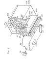
- Figs. 1 to 5 illustrate one embodiment of the present invention.
- a sewage settling pool (a treatment pool) rectangular in shape as viewed from above, and this rectangular sewage settling pool is provided, as shown in Fig. 3, with a plurality of, for example, four, sprocket shafts 300 supported so as to extend in a widthwise direction of the sewage settling pool, a pair of sprocket wheels 301 rigidly mounted on each of the sprocket shafts 300 and generally endless left-hand and right-hand chains 302 trained around the respective sprocket wheels 301 on each sprocket shaft 300.
- a plurality of flights 303 are mounted on the endless chains 302 in a substantially equally spaced relationship around the chains 302 so that the flights 303 can undergo a circulatory motion along a generally rectangular path together with the chains 302.
- a bracket 304 is secured to one of opposite ends of all or some of the flights 303 (that end over the flight 303 shown in Fig. 1 so far as the illustrated embodiment is concerned) and carries a roller support shaft so as to extend outwardly therefrom with a roller 305 mounted on a free end of such roller support shaft.
- This roller 305 on all or some of the flights 303 can undergo a circulatory motion along a generally rectangular path including an upper horizontal path component adjacent a fluid surface level 306 of the sewage in the sewage settling pool extending in a direction shown by the arrow in Fig. 1, a diagonally downwardly lowering path component, a lower horizontal path component extending along the bottom of the sewage settling pool and an elevating path component, before it is brought to a position immediately beneath the fluid surface level 306.
- a scum removal apparatus is provided with a trough 308.
- This trough 308 is of a generally U-shaped cross-section and includes a rear wall 308a, a major portion of which is sunken beneath the fluid surface level 306, but having an upper portion protruding above the fluid surface level 306, a bottom wall 308b positioned beneath the fluid surface level 306, and a front wall 308c of a height lower than that of the rear wall 308a having an upper portion positioned beneath, but adjacent to the fluid surface level 306.
- a front flange 308d is integrally formed with the front wall 308c so as to protrude frontwardly from the upper portion thereof in a direction opposite to the rear wall 308a.
- the trough 308 is of the generally U-shaped cross-section opening upwardly and, also, diagonally frontwardly and is of a length slightly smaller than the width of the sewage settling pool.
- This trough 308 is fixedly installed in the sewage settling pool with its lengthwise direction oriented widthwise of the sewage settling pool. Opposite ends of the trough 308 are provided with respective end plates 308e.
- a connecting trough 311 inserted through and fixed in a wall forming the sewage settling pool with its opposite ends protruding outwardly in opposite directions from the wall of the sewage settling pool is bolted to each end plate 308e by means of a flange 311a integral with the connecting trough 311.
- the connecting trough 311 is of a generally square cross-section and is used to communicate the troughs 311 in the neighboring sewage settling pools. It is to be noted that the trough 308 is so slightly inclined with one end thereof held at a level higher than the opposite end thereof that fluid can flow from the higher end of the trough 308 towards the lower end thereof by the effect of a gravitational force. This can in practice be accomplished by setting the bottom wall 308b of the trough 308 inclined. Therefore, scum and water component can be gathered having flowed in one direction and then guided to the next succeeding treatment system.
- An elongated bottom seal member 312 of a generally U-shaped cross-section made of rubber material is rigidly secured to the front flange 308d by means of an elongated retainer plate 313.
- This bottom seal member 312 has rear and front wall portions, the rear portion having a height greater than that of the front wall portion.
- Bearings 314 are fixedly connected to opposite respective ends of the front flange 308d, and a tubular rotary shaft 315 is supported by these bearings 314 so as to extend substantially parallel to the front flange 308d.
- a weir member (a float) 317 is supported by the rotary shaft 315 so as to undergo a rocking motion about the longitudinal axis of the rotary shaft 315.
- the weir member 317 is of a generally flat tubular configuration having a generally elliptical cross-section and of a length sufficient to extend widthwise of the sewage settling pool.
- the rotary shaft 315 has front and rear rounded sides with the rotary shaft 315 extending through the rear rounded side thereof. Opposite ends of the weir member 317 have respective end plates 318 rigidly secured thereto with opposite ends of the rotary shaft 315 extending outwardly therethrough to left-hand and right-hand sides.
- the sealing means 320 comprises a fixed plate 321 fixed to each end of the trough 308 so as to extend upright and having a gap between left-hand and right-hand portions thereof, flat rubber seal plates 322 disposed on respective sides of the fixed plate 321, main seals 323 each having one end formed into a tapered lip and seal retainers 324, all of which are fastened together by means of bolts and nuts.
- the end plates 318 can move from and aft in gaps formed among these elements to avoid any possible leakage of water component from the front.
- the front rounded side of the weir member 317 has a plurality of recesses 317a defined therein so that relatively large scum lumps can be drawn by these recesses 317a.
- Reference numeral 325 represents a bracket secured to a side wall 310 of the sewage settling pool.
- This bracket 325 has a single operating arm 327 having a generally intermediate portion rotatably connected thereto by means of a rotary support shaft 326 while extending transverse to the rotary support shaft 326.
- the operating arm 327 has a front free end provided with a follow-up member 328 and also has a rear free end operatively coupled with a rod 329.
- an supplemental element 331 may be connected to one or each end of the weir member 317 by means of a bolt 330 threaded thereto through the supplemental element 331 as shown in Fig. 5.
- the supplemental element 331 may have its tip provided with sharp projections 333 effective to break the scum S into pieces.
- a shaft X may be mounted by a plurality of bearing (not shown) so as to extend parallel to the lengthwise direction of the sewage settling pool for rotation about the longitudinal axis thereof and that an auxiliary arm 328b may be connected to the shaft X so as to extend perpendicular thereto while a follow-up member 328a having a free end provided with a plurality of corrugations is fitted to a free end of the arm 328b.
- the follow-up member 328a is selectively shifted upwardly and downwardly about the shaft X to thereby cause the weir member 317 to be elevated and lowered by a transmission mechanism with respect to the fluid surface level 306.
- the scum removal apparatus is installed in the initial or final sewage settling pool and is useful as a handy apparatus for removing and collecting scum floating on the fluid surface level.
- the present invention is so designed as to be applicable to all apparatuses operable to remove and collect the scum by the utilization of the driving power delivered from the existing movable member in the sewage treatment pool and can be manufactured very compact in size and at a reduced cost while satisfying the demands of each installability at site.
Landscapes
- Chemical & Material Sciences (AREA)
- Chemical Kinetics & Catalysis (AREA)
- Removal Of Floating Material (AREA)
Abstract
Claims (2)
- Dispositif d'élimination de boues surnageantes qui comprend :caractérisé en ce queune auge à section générale en U (308, 205) pouvant être installée de façon fixe dans un bassin de traitement d'effluents, tel qu'un bassin de décantation d'effluents, une partie inférieure de celle-ci devant être immergée en dessous d'un niveau de surface de fluide (306, 207) dans le bassin de traitement d'effluents et une partie supérieure de celle-ci émergeant vers le haut au-dessus du niveau de surface de fluide, ladite auge (308, 205) comportant une ouverture définie d'un côté de celle-ci, ladite auge pouvant être mise en oeuvre pour rejeter les boues surnageantes et une composante d'eau qui ont été introduites dans celle-ci par l'intermédiaire de l'ouverture,un élément de déversoir (317, 208) prévu à proximité de l'ouverture de l'auge (308, 205) de façon à subir un mouvement basculant, une partie latérale supérieure de celui-ci montant et descendant par rapport au niveau de la surface de fluide (306, 207) afin de guider et d'interrompre l'écoulement des boues surnageantes et de la composante d'eau dans l'auge, etun mécanisme de transmission (209) destiné à transmettre une force à l'élément de déversoir (307, 208) de façon à amener l'élément de déversoir à subir le mouvement de basculement et comprenant un élément suiveur (328, 213) conçu pour être actionné en contact avec une unité d'entraínement prévue dans chacune de lames (303, 203) à l'intérieur du bassin de traitement, dans lequel l'auge est munie d'un arbre rotatif pour permettre à l'élément de déversoir de monter et descendre,
un côté de l'auge (308) adjacent à l'ouverture est muni du [d'un] arbre rotatif qui s'étend parallèlement au niveau de la surface du fluide (306) et ledit élément de déversoir (317) est un élément généralement allongé présentant une section transversale elliptique. - Dispositif d'élimination de boues surnageantes selon la revendication 1
caractérisé en ce que
ledit élément de déversoir (317) a ses extrémités opposées munies de plaques d'extrémité respectives (318) alors que ladite auge est munie de moyens d'étanchéité (320) prenant en sandwich chacune des plaques d'extrémité (318) en vue d'une étanchéité entre l'auge (308) et les plaques d'extrémité associées.
Applications Claiming Priority (4)
| Application Number | Priority Date | Filing Date | Title |
|---|---|---|---|
| JP036050U JPH0585491U (ja) | 1992-04-14 | 1992-04-14 | スカム除去装置 |
| JP3605092U | 1992-04-14 | ||
| JP36050/92U | 1992-04-14 | ||
| PCT/JP1992/001038 WO1993021113A1 (fr) | 1992-04-14 | 1992-08-13 | Dispositif de decrassage |
Publications (3)
| Publication Number | Publication Date |
|---|---|
| EP0607436A1 EP0607436A1 (fr) | 1994-07-27 |
| EP0607436A4 EP0607436A4 (en) | 1994-09-14 |
| EP0607436B1 true EP0607436B1 (fr) | 2001-07-04 |
Family
ID=12458891
Family Applications (1)
| Application Number | Title | Priority Date | Filing Date |
|---|---|---|---|
| EP92917808A Expired - Lifetime EP0607436B1 (fr) | 1992-04-14 | 1992-08-13 | Dispositif de decrassage |
Country Status (8)
| Country | Link |
|---|---|
| US (1) | US5423987A (fr) |
| EP (1) | EP0607436B1 (fr) |
| JP (2) | JPH0585491U (fr) |
| AU (1) | AU2431192A (fr) |
| CA (1) | CA2111473C (fr) |
| DE (1) | DE69231917D1 (fr) |
| TW (1) | TW204331B (fr) |
| WO (1) | WO1993021113A1 (fr) |
Families Citing this family (6)
| Publication number | Priority date | Publication date | Assignee | Title |
|---|---|---|---|---|
| US7258788B2 (en) * | 2004-03-12 | 2007-08-21 | Noram Engineering And Constructors Ltd. | Circular clarifier apparatus and method |
| FI116715B (fi) * | 2004-06-29 | 2006-02-15 | Finnketju Invest Oy | Menetelmä ja järjestely pintalietteen poistoon |
| JP5895268B2 (ja) * | 2012-07-16 | 2016-03-30 | 有限会社フジカ | スカム除去装置 |
| JP2016005448A (ja) * | 2014-03-17 | 2016-01-14 | 雅文 玉川 | 浮遊物除去取水装置 |
| US11092189B2 (en) * | 2018-05-08 | 2021-08-17 | Brentwood Industries, Inc. | Head shaft assembly and related method |
| US11702350B2 (en) * | 2021-01-20 | 2023-07-18 | Monte Whetstone | Surface skimmer lifting device |
Family Cites Families (20)
| Publication number | Priority date | Publication date | Assignee | Title |
|---|---|---|---|---|
| US3081879A (en) * | 1960-04-29 | 1963-03-19 | Standard Oil Co | Skimming apparatus |
| DE2610499A1 (de) * | 1976-03-12 | 1977-09-15 | Ulrich Dr Ing Stahl | Raeumvorrichtung fuer rechteckige absetzbecken |
| JPS5845396B2 (ja) * | 1977-02-21 | 1983-10-08 | 三菱重工業株式会社 | 流出油回収装置 |
| JPS607830Y2 (ja) * | 1978-03-08 | 1985-03-16 | 日立造船株式会社 | 海上石油備蓄基地における漏洩油回収装置 |
| US4277334A (en) * | 1980-02-11 | 1981-07-07 | Texaco Inc. | Oil and debris skimmer |
| US4268394A (en) * | 1980-03-28 | 1981-05-19 | Sybron Corporation | Beach for the scum trough of a sewage settling tank or the like |
| US4468830A (en) * | 1983-06-24 | 1984-09-04 | Libman Broom Company | Sponge mop |
| JPH01124288A (ja) * | 1987-11-09 | 1989-05-17 | Mitsubishi Electric Corp | 半導体装置 |
| JPH01124288U (fr) * | 1988-02-17 | 1989-08-24 | ||
| IT1234582B (it) * | 1988-03-22 | 1992-05-25 | Mirella De Toffoli | Procedimento per pulire le acque dai rifiuti oleosi galleggiantivi e relativi apparati, di peso modesto, funzionanti senza personale a bordo e con efficienza di pulizia e raccolta alta anche con mare mosso |
| JPH0253191A (ja) * | 1988-08-16 | 1990-02-22 | Nec Corp | バーコード読取装置 |
| JP2562010Y2 (ja) * | 1988-10-03 | 1998-02-04 | 充弘 藤原 | スカム除去装置 |
| DE3921826C1 (fr) * | 1989-07-03 | 1990-09-06 | August Bilstein Gmbh & Co Kg, 5828 Ennepetal, De | |
| JPH0390689A (ja) * | 1989-09-01 | 1991-04-16 | Oji Paper Co Ltd | 改質パルプの製造方法 |
| JPH0390689U (fr) * | 1989-12-27 | 1991-09-17 | ||
| JP2532560Y2 (ja) * | 1990-03-07 | 1997-04-16 | 充弘 藤原 | スカム処理装置 |
| US5057219A (en) * | 1990-05-02 | 1991-10-15 | Michihiro Fujiwara | Scum treating apparatus |
| US5200079A (en) * | 1990-06-20 | 1993-04-06 | Mcnish Corporation | Circular clarifier including improved skimmer clarifier |
| DE9201328U1 (de) * | 1992-02-04 | 1992-04-09 | Eisenmann Maschinenbau KG (Komplementär: Eisenmann-Stiftung), 7030 Böblingen | Vorrichtung zum Abscheiden und Austragen von durch Koagulierung entklebter Lackpartikel aus dem Abwasser von Farbspritzkabinen |
| JP3109693U (ja) | 2005-01-13 | 2005-05-19 | 株式会社エス・ティー・シー | 便器 |
-
1992
- 1992-04-14 JP JP036050U patent/JPH0585491U/ja active Pending
- 1992-08-13 US US08/150,208 patent/US5423987A/en not_active Expired - Lifetime
- 1992-08-13 EP EP92917808A patent/EP0607436B1/fr not_active Expired - Lifetime
- 1992-08-13 AU AU24311/92A patent/AU2431192A/en not_active Abandoned
- 1992-08-13 DE DE69231917T patent/DE69231917D1/de not_active Expired - Lifetime
- 1992-08-13 WO PCT/JP1992/001038 patent/WO1993021113A1/fr not_active Ceased
- 1992-08-13 CA CA002111473A patent/CA2111473C/fr not_active Expired - Fee Related
- 1992-09-14 TW TW081107200A patent/TW204331B/zh not_active IP Right Cessation
- 1992-12-22 JP JP1992094262U patent/JP2582163Y2/ja not_active Expired - Lifetime
Also Published As
| Publication number | Publication date |
|---|---|
| AU2431192A (en) | 1993-11-18 |
| CA2111473A1 (fr) | 1993-10-28 |
| EP0607436A1 (fr) | 1994-07-27 |
| TW204331B (en) | 1993-04-21 |
| CA2111473C (fr) | 2000-03-14 |
| EP0607436A4 (en) | 1994-09-14 |
| JP2582163Y2 (ja) | 1998-09-30 |
| JPH0585491U (ja) | 1993-11-19 |
| DE69231917D1 (de) | 2001-08-09 |
| JPH0670890U (ja) | 1994-10-04 |
| US5423987A (en) | 1995-06-13 |
| WO1993021113A1 (fr) | 1993-10-28 |
Similar Documents
| Publication | Publication Date | Title |
|---|---|---|
| CA2034862C (fr) | Dispositif automoteur de nettoyage de bassin d'epuration d'eau | |
| US4054520A (en) | Scum removal system for a sewage settling tank | |
| EP0607436B1 (fr) | Dispositif de decrassage | |
| US4005019A (en) | Gravitational separator | |
| US5047150A (en) | Settled solids removal mechanism | |
| US4731180A (en) | Water-solids separator and wiper blade | |
| EP0574023A1 (fr) | Racleur de plafond flottant pour des bacs de décantation superposés | |
| KR101995902B1 (ko) | 자동 승강식 제진기 | |
| KR102139901B1 (ko) | 부유물 데드존이 없는 무한궤도형 슬러지 수집기 | |
| KR20020092765A (ko) | 로터리식 제진기 | |
| KR200175037Y1 (ko) | 제진기 | |
| CN213651920U (zh) | 一种新型气浮装置刮渣机 | |
| KR102728624B1 (ko) | 레이크 순환회전 부하절감 구조를 갖는 소비전력 절감형 제진기 | |
| JP3234737B2 (ja) | 汚泥掻寄機 | |
| CN117945503A (zh) | 城市污水处理设备 | |
| KR101740376B1 (ko) | 와이어로프 견인식 사이폰 슬러지 수집기 | |
| CN213834633U (zh) | 含油污漂浮物污水前处理装置 | |
| JPH08267059A (ja) | 汚泥掻寄機 | |
| KR100623221B1 (ko) | 하천 수로의 쓰레기 수거장치 | |
| KR200359282Y1 (ko) | 하천 수로의 쓰레기 수거장치 | |
| KR102728625B1 (ko) | 레이크 순환회전 부하절감 구조를 갖는 소비전력 절감형 링크식 제진기 | |
| KR100231300B1 (ko) | 계단식여과기에 있어서 톱니형격자판 | |
| CN121020757A (zh) | 一种乳化剂生产的废水净化处理装置 | |
| CN224207489U (zh) | 一种往复式表面浮渣清理装置 | |
| JP2587347Y2 (ja) | 河川用汚泥掻寄装置 |
Legal Events
| Date | Code | Title | Description |
|---|---|---|---|
| PUAI | Public reference made under article 153(3) epc to a published international application that has entered the european phase |
Free format text: ORIGINAL CODE: 0009012 |
|
| 17P | Request for examination filed |
Effective date: 19931223 |
|
| AK | Designated contracting states |
Kind code of ref document: A1 Designated state(s): BE DE FR GB NL |
|
| A4 | Supplementary search report drawn up and despatched | ||
| AK | Designated contracting states |
Kind code of ref document: A4 Designated state(s): BE DE FR GB NL |
|
| 17Q | First examination report despatched |
Effective date: 19951201 |
|
| GRAG | Despatch of communication of intention to grant |
Free format text: ORIGINAL CODE: EPIDOS AGRA |
|
| GRAG | Despatch of communication of intention to grant |
Free format text: ORIGINAL CODE: EPIDOS AGRA |
|
| GRAH | Despatch of communication of intention to grant a patent |
Free format text: ORIGINAL CODE: EPIDOS IGRA |
|
| GRAH | Despatch of communication of intention to grant a patent |
Free format text: ORIGINAL CODE: EPIDOS IGRA |
|
| GRAA | (expected) grant |
Free format text: ORIGINAL CODE: 0009210 |
|
| AK | Designated contracting states |
Kind code of ref document: B1 Designated state(s): BE DE FR GB NL |
|
| PG25 | Lapsed in a contracting state [announced via postgrant information from national office to epo] |
Ref country code: NL Free format text: LAPSE BECAUSE OF FAILURE TO SUBMIT A TRANSLATION OF THE DESCRIPTION OR TO PAY THE FEE WITHIN THE PRESCRIBED TIME-LIMIT Effective date: 20010704 Ref country code: FR Free format text: LAPSE BECAUSE OF FAILURE TO SUBMIT A TRANSLATION OF THE DESCRIPTION OR TO PAY THE FEE WITHIN THE PRESCRIBED TIME-LIMIT Effective date: 20010704 Ref country code: BE Free format text: LAPSE BECAUSE OF FAILURE TO SUBMIT A TRANSLATION OF THE DESCRIPTION OR TO PAY THE FEE WITHIN THE PRESCRIBED TIME-LIMIT Effective date: 20010704 |
|
| REF | Corresponds to: |
Ref document number: 69231917 Country of ref document: DE Date of ref document: 20010809 |
|
| PG25 | Lapsed in a contracting state [announced via postgrant information from national office to epo] |
Ref country code: GB Free format text: LAPSE BECAUSE OF NON-PAYMENT OF DUE FEES Effective date: 20011004 |
|
| PG25 | Lapsed in a contracting state [announced via postgrant information from national office to epo] |
Ref country code: DE Free format text: LAPSE BECAUSE OF FAILURE TO SUBMIT A TRANSLATION OF THE DESCRIPTION OR TO PAY THE FEE WITHIN THE PRESCRIBED TIME-LIMIT Effective date: 20011005 |
|
| NLV1 | Nl: lapsed or annulled due to failure to fulfill the requirements of art. 29p and 29m of the patents act | ||
| EN | Fr: translation not filed | ||
| REG | Reference to a national code |
Ref country code: GB Ref legal event code: IF02 |
|
| PLBE | No opposition filed within time limit |
Free format text: ORIGINAL CODE: 0009261 |
|
| GBPC | Gb: european patent ceased through non-payment of renewal fee |
Effective date: 20011004 |
|
| 26N | No opposition filed |