EP0607455A1 - Dispositif d'autodiagnostic pour vehicule - Google Patents
Dispositif d'autodiagnostic pour vehicule Download PDFInfo
- Publication number
- EP0607455A1 EP0607455A1 EP93916209A EP93916209A EP0607455A1 EP 0607455 A1 EP0607455 A1 EP 0607455A1 EP 93916209 A EP93916209 A EP 93916209A EP 93916209 A EP93916209 A EP 93916209A EP 0607455 A1 EP0607455 A1 EP 0607455A1
- Authority
- EP
- European Patent Office
- Prior art keywords
- diagnostic data
- malfunction
- storing
- detecting
- self
- Prior art date
- Legal status (The legal status is an assumption and is not a legal conclusion. Google has not performed a legal analysis and makes no representation as to the accuracy of the status listed.)
- Granted
Links
- 238000001514 detection method Methods 0.000 claims abstract description 38
- 238000000034 method Methods 0.000 claims abstract description 18
- 230000007257 malfunction Effects 0.000 claims description 146
- 230000002401 inhibitory effect Effects 0.000 claims description 7
- 230000004044 response Effects 0.000 claims description 5
- 238000010276 construction Methods 0.000 description 8
- 239000000446 fuel Substances 0.000 description 5
- XLYOFNOQVPJJNP-UHFFFAOYSA-N water Substances O XLYOFNOQVPJJNP-UHFFFAOYSA-N 0.000 description 5
- 230000003247 decreasing effect Effects 0.000 description 4
- 238000010586 diagram Methods 0.000 description 3
- 230000006870 function Effects 0.000 description 2
- 101000609957 Homo sapiens PTB-containing, cubilin and LRP1-interacting protein Proteins 0.000 description 1
- 101150109471 PID2 gene Proteins 0.000 description 1
- 102100039157 PTB-containing, cubilin and LRP1-interacting protein Human genes 0.000 description 1
- 230000005856 abnormality Effects 0.000 description 1
- 230000008014 freezing Effects 0.000 description 1
- 238000007710 freezing Methods 0.000 description 1
- 238000007689 inspection Methods 0.000 description 1
- 230000010355 oscillation Effects 0.000 description 1
- 238000007493 shaping process Methods 0.000 description 1
- 238000011144 upstream manufacturing Methods 0.000 description 1
Images






Classifications
-
- F—MECHANICAL ENGINEERING; LIGHTING; HEATING; WEAPONS; BLASTING
- F02—COMBUSTION ENGINES; HOT-GAS OR COMBUSTION-PRODUCT ENGINE PLANTS
- F02D—CONTROLLING COMBUSTION ENGINES
- F02D41/00—Electrical control of supply of combustible mixture or its constituents
- F02D41/24—Electrical control of supply of combustible mixture or its constituents characterised by the use of digital means
- F02D41/26—Electrical control of supply of combustible mixture or its constituents characterised by the use of digital means using computer, e.g. microprocessor
- F02D41/266—Electrical control of supply of combustible mixture or its constituents characterised by the use of digital means using computer, e.g. microprocessor the computer being backed-up or assisted by another circuit, e.g. analogue
-
- F—MECHANICAL ENGINEERING; LIGHTING; HEATING; WEAPONS; BLASTING
- F02—COMBUSTION ENGINES; HOT-GAS OR COMBUSTION-PRODUCT ENGINE PLANTS
- F02D—CONTROLLING COMBUSTION ENGINES
- F02D41/00—Electrical control of supply of combustible mixture or its constituents
- F02D41/22—Safety or indicating devices for abnormal conditions
Definitions
- the present invention relates to a self-diagnosing apparatus for motor vehicles which stores diagnostic data necessary for analyzing malfunctions of instruments installed in such motor vehicle.
- Instruments including, among other things, the engine, installed in each section of a motor vehicle are interconnected to each other via a control computer so that complex operations can be performed.
- a self-diagnosing apparatus in which diagnostic data from each section of a motor vehicle is updated and stored in a memory where the contents are stored at specified intervals even when the power supply is shut down; updating of the contents of the memory being inhibited (frozen) after a malfunction of the installed instrument is detected, so that the cause of the malfunction can be determined accurately after getting out of the motor vehicle.
- the above-mentioned diagnostic data is stored by a microcomputer operation, it takes some time, though slight, from when a malfunction is detected until data is frozen. If the ignition switch is turned off between the time of malfunction detection and freezing the data, the microcomputer stops its processing, and the diagnostic data obtained before the ignition switch has been turned off is not frozen. Therefore, the diagnostic data is reset to an initial state when the ignition switch is turned on again to start the control program, making it impossible to analyze the malfunction, which is problematical.
- diagnostic data obtained when a malfunction is detected again after the ignition switch is turned on again is frozen despite the first detection of the malfunction before the ignition switch has been turned off, diagnostic data (data obtained when the ignition switch is turned on again) different from that when the first malfunction has occurred, will be output. As a result, there is a risk that the cause of the malfunction will be analyzed erroneously, or it will become impossible to investigate the cause of the malfunction.
- the diagnostic data is stored and updated in the memory at regular intervals up to the time a malfunction occurs. This storing and updating becomes a burden depending upon the computing speed of the CPU, and it is conceivable that the diagnostic data is stored and frozen only after the occurrence of the malfunction is detected.
- the present invention solves the above-described problems of the prior art. It is an object of the present invention to accurately analyze the cause of a malfunction even when the power supply is shut off immediately after the malfunction is detected.
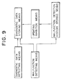
- the present invention comprises diagnostic data detecting means for detecting diagnostic data necessary for analyzing malfunctions of instruments installed in a motor vehicle; malfunction detecting means for detecting the malfunction of instruments installed in a motor vehicle; malfunction detection history storing means for storing the malfunction detection history of the malfunction detecting means and holding the storage thereof even when an ignition switch is off; diagnostic data storing means for storing diagnostic data detected by the diagnostic data detecting means after the malfunction of the instruments installed in the motor vehicle is detected and holding the storage thereof even when the ignition switch is off; and updating inhibiting means for inhibiting the updating of diagnostic data stored in the diagnostic data storing means when the detection history stored in the malfunction detection history storing means is referenced after the ignition switch is turned on and when there is a detection history.
- the diagnostic data of the storing means is lost by initialization reset when the ignition switch is turned on next.
- the malfunction detection history before the ignition switch is turned on is referenced; when there is a detection history, the updating of the diagnostic data is inhibited. Therefore, the diagnostic data will not be reset erroneously.
- the diagnostic data when the previous malfunction has been detected will not be erroneously reset when the power supply is turned on again.
- the present invention comprises means for detecting the malfunction of each instrument installed in a motor vehicle; storing means for holding the contents when the ignition switch is in an off state; means for storing diagnostic data necessary for setting a flag bit in a predetermined position of the storing means when an instrument malfunction is detected and storing diagnostic data necessary for analyzing later the malfunctions of instruments; and means for resetting the flag bit after all the diagnostic data is stored.
- the flag bit is set prior to the storing of the diagnostic data when a malfunction is detected. Since this flag bit is reset after all the diagnostic data is completely stored, if the power supply is shut off while the diagnostic data is being stored, the flag bit will not be reset. Therefore, if the setting/non-setting of the flag bit is confirmed when diagnostic data is read out, erroneous diagnostic data will not be read out.
- this turning-off is determined on the basis of the setting/non-setting of the flag bit, so that the reading of erroneous diagnostic data can be reliably avoided.
- the malfunction occurrence is stored temporarily, and then updating of diagnostic data which has been updated and stored in sequence is inhibited.
- the ignition switch is turned on and before the diagnostic data is updated and stored, it is first confirmed that the diagnostic data is temporarily stored.
- further updating and storing is inhibited.
- the fact that the storing of the diagnostic data is not terminated because the power has been shut off by the ignition switch immediately after the malfunction occurred can be confirmed by the presence of the above-described temporary storage. Since in this first embodiment, updating and storing is inhibited once again after the ignition switch is turned on again, it is possible to store diagnostic data when a malfunction occurs, making it possible to accurately analyze the malfunction.
- a potentiometer 21 of a flow meter 31 an intake-air temperature sensor 24, a throttle sensor 27 of a throttle valve 32, and a fuel discharge valve 29 are disposed in the upstream portion of an intake-air pipe E1 of an engine E.
- a water temperature sensor 23 is disposed in a water jacket of the engine E, and an O2 sensor 22 is disposed in a discharge pipe E2 of the engine E.
- a control unit 1 having a CPU 101 contained therein is disposed, and the CPU 101 is connected via a data bus to a RAM 102, a ROM 103, an oscillation circuit 104, input/output ports 105A and 105B, and output ports 106A, 106B, and 106C.
- the RAM 102 is separated into a common RAM for temporary storage and a standby RAM in which the contents at the time the ignition key is turned off are held.
- Output signals from the potentiometer 21, the O2 sensor 22, the water temperature sensor 23, the intake-air temperature sensor 24 and the throttle sensor 27 are input through a multiplexer 107 and an A/D converter 108 to the input/output port 105A.
- Output signals from a cylinder determination sensor 25 and a rotational angle sensor 26 are input through a waveform shaping circuit 109 to the input/output port 105B.
- the output signals are supplied via output ports 106B and 106C to an igniter 28 and the fuel discharge valve 29.
- Fig. 3 shows a program for detecting a malfunction of the throttle sensor 27.
- S101 a check is made to determine whether a throttle opening signal is in the range from 0.1 V to 4.9 V (S101, S102). If the signal is in this range, the fail counter is cleared, and the fail flag in the common RAM is cleared (S105, S106). If, on the other hand, the time during which the signal is not present in the above-mentioned range exceeds 500 ms (S103), it is assumed that the throttle sensor has a malfunction, and the fail flag is set (S104).
- Fig. 4 shows a program for inputting into the standby RAM the fact that the above-mentioned fail flags are set, which program is activated at intervals of every 65 ms.
- S201 a check is made to determine whether writing in the standby RAM is possible.
- predetermined bits of the standby RAM are set (S202, S203), so that the fact that a specific instrument malfunctions has been detected is stored.
- the memory configuration of the standby RAM is shown in Fig. 5. Diagnostic data, such as the number of rotations of the engine or water temperature of the engine, are stored in sequence in corresponding addresses within the frame. An abnormality code indicating the type of the malfunction is set at the beginning address thereof as described later.
- Fig. 6 shows a program for controlling writing in the standby RAM.
- the program is activated at intervals of every 65 ms.
- S301 a check is made to determine whether the malfunction code has been set. If the code has not been set, the diagnostic data stored in the previous cycle is updated into the newly input diagnostic data (S302).
- S303, S304 When the malfunction code has been set in the predetermined bits of the standby RAM under this condition, it is assumed that a malfunction has been detected and the above-described malfunction code is set (S303, S304).
- S303, S304 When a malfunction code has been set in S301, updating is inhibited, and the diagnostic data is frozen.
- Fig. 7 shows an initial program which is executed only once when the ignition switch is turned on.
- the common RAM is initialized (S401)
- the malfunction code has been not set it is confirmed whether the fail flag of the standby RAM has been set (S403).
- S404 the malfunction code is set to inhibit the updating of the standby RAM, so that the diagnostic data is placed in the frozen state.
- Fig. 8 shows a program for connecting a fault diagnosing apparatus after getting out of the motor vehicle and transmitting diagnostic data, which program is activated every 16 ms.
- a check is made to determine if frozen diagnostic data has been requested from the diagnosing apparatus, and diagnostic data for the PID request is selected (S502).
- the PID request is one in which diagnostic data is requested in an ID format from the diagnosing apparatus.
- PID1 is the number of rotations of the engine
- PID2 is the speed of the motor vehicle.
- the fail flag is set first in response to the detection of the malfunction, and then data is updated and stored and the malfunction code is stored. The setting/non-setting of the fail flag is determined when the ignition switch is turned on the next time to determine whether a malfunction has occurred previously while the ignition switch was on, inhibiting the updating and storing of data.
- the valuable data updated and stored immediately after the malfunction while the ignition switch is being turned on at the previous time can be prevented from being lost after the ignition switch is turned on the next time.
- the operation in which only a malfunction occurs in the throttle sensor it is known that various malfunctions can be detected as regards malfunctions of instruments installed in a motor vehicle, and the present invention can he applied in conjunction with the detection of various malfunctions of instruments installed in a motor vehicle. It may be possible to erase old data before data is updated and stored and then store new data. Even when the ignition switch is turned off while data obtained after a malfunction occurs is being updated and updating of the data is terminated in the middle of the updating operation, it is possible to store only data obtained immediately after the malfunction has occurred.
- the method for updating and storing data is not limited to one in which the data is updated and stored at predetermined intervals; data may also be updated and stored only when a malfunction is detected.
- data when data is updated and stored at predetermined intervals, data may be stored while cyclically switching sequentially a plurality of storage areas. When a malfunction is detected, updating and storing in all these storage areas is inhibited to freeze the data, so that data obtained immediately after the malfunction is detected, as well as the process leading to the malfunction occurrence can be analyzed.
- a malfunction occurrence is temporarily stored immediately after the malfunction occurs. Thereafter, a plurality of diagnostic data are stored in sequence, and after this storage operation is terminated, the above temporary storage is erased. Thus, the fact can be confirmed that the power supply has been shut off by the ignition switch immediately after the malfunction occurred and that the diagnostic data storing operation has not been terminated.
- outputting of diagnostic data is inhibited when the above-described temporary storage is present, thus preventing erroneous analysis.
- a control unit 51 comprises a CPU 61, a ROM 62, a RAM 63, an input/output (I/O) circuit 64, and a comparator 65.
- Power is supplied from a battery 53 through an ignition switch 52 to the CPU 61, the ROM 62, the RAM 63 and the I/O circuit 64.
- Power is directly supplied to a part of the RAM 63 from the battery 53 so that it works as a standby RAM in which the contents of the storage are maintained even when the ignition switch 52 is turned off.
- the battery voltage is input to a comparator 65 where it is compared with a reference voltage; this comparison is input to a latch port of the I/O circuit 64. Then, when the battery voltage is decreased, a "1" level output is generated from the comparator 65, causing a voltage decrease latch within I/O circuit 64 to be set.
- Sensor signals are input to an I/O circuit 64 from the sensors disposed in the various sections of the motor vehicle, such as a throttle sensor 71, an air-flow meter 72, a crank angle sensor 73, or a water temperature sensor 74.
- the amount of fuel injected is determined by a CPU 61 in accordance with the sensor signals according to the control programs within a ROM 62.
- An output signal corresponding to the amount of fuel injected is output through the I/O circuit 64 to a fuel discharge valve 75.
- a diagnostic checker 54 is connected to the I/O circuit 64 as shown in the figure, and the diagnostic data frozen within the RAM 63 is read out.
- Fig. 11 shows a program for detecting a malfunction of the throttle sensor as an example.
- step (hereinafter referred to as S) 151 and S152 a check is made to determine whether a throttle opening signal is in the range from 0.1 V to 4.9 V. If the signal is in this range, the fail flag in the RAM 63 is cleared (S155, S156). If, on the other hand, the time during which the signal is not present in the above-mentioned range exceeds 500 ms (S153), it is assumed that the throttle sensor has a malfunction, and the fail flag is set (S154).
- Fig. 12 shows a program for inputting into the standby RAM the fact that the above-mentioned fail flag is set, which program is activated at intervals of every 65 ms.
- S251 a check is made to determine whether writing in the standby RAM is possible.
- predetermined bits of the standby RAM are set (S252, S253), so that the fact that a specific instrument malfunctions has been detected is stored.
- the memory configuration of the standby RAM is shown in Fig. 13.
- a plurality of storage frames are secured in the standby RAM (one of which is shown in the figure).
- a flag bit, together with a malfunction code determined in accordance with the type of a malfunction, is set at the beginning address of each frame.
- Diagnostic data useful for analyzing the malfunction such as the number of rotations of the engine (NE) or the speed (SPD) of the motor vehicle, is stored in sequence in the addresses after the beginning address. Each diagnostic data is stored in 8 or 16 bits.
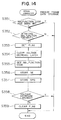
- Fig. 14 shows a program for controlling writing of diagnostic data in the standby RAM, which program is activated at intervals of every 65 ms.
- S351 a check is made to determine whether the malfunction code has been set. If the malfunction code has not been set, a check is made to determine whether the predetermined bits of the standby RAM are set and a malfunction has been detected (S352). When the malfunction has been detected, the process proceeds to S353 and subsequent steps.
- a flag bit (Fig. 13) is set in the above-described beginning address, and then a voltage decrease latch within the I/O circuit 64 is cleared (S354).
- the malfunction code is set, and then diagnostic data, such as the number of rotations of the engine (NE) or the speed (SPD) of the motor vehicle, is stored in sequence (S356, S357).
- diagnostic data such as the number of rotations of the engine (NE) or the speed (SPD) of the motor vehicle.
- S358 a check is made to determine whether the voltage decrease latch has been set. If it has not been set, the above-mentioned flag bit is cleared (S359).
- Fig. 15 shows in (2) thereof a case in which the ignition switch is turned off while the diagnostic data is being stored. Since the program is not run after the power supply is shut off, the flag bit remains set.
- Fig. 15 shows in (3) thereof a case in which the voltage of the power supply is decreased while the diagnostic data is being stored. Since the voltage decrease latch is set when the voltage is decreased, S359 is not executed, and the flag bit remains set.
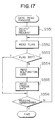
- Fig. 16 shows a program for outputting diagnostic data from the control unit 51 side to the diagnostic checker 54 connected to the I/O circuit 64.
- a check is made in S451 to determine whether there has been a data output request from the diagnostic checker.
- S452 it is confirmed in S452 that the above-described flag bit has not been set in a storage frame to be output in S452, and the malfunction code and the frozen diagnostic data are read out (S453, S454). This is performed for all the storage frames, terminating data output (S455). Since the diagnostic data of the frame is not output if the flag bit has been set, outputting of data from the frame where erroneous data has been stored because the ignition switch has been turned off while data is being stored or the voltage is decreased can be prevented.
- Fig. 16 shows an example in which a process for preventing erroneous data from being output from the control unit side is installed within the diagnostic data output process in the control unit 51 side.
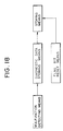
- the diagnostic checker 54 side it is also possible for the diagnostic checker 54 side to determine whether or not the data frozen in the control unit 51 is erroneous and then to read the data.
- a data request is output to the CPU 61 of the control unit 51 in S551, and the flag bit is read out in S552. After it is confirmed that the flag bit has not been set, a malfunction code and diagnostic data are read out from the frame (S553, S554, S555). When the flag bit has been set, the diagnostic data is not read out.
- control unit 51 does not perform such an output process as that shown in Fig. 16, but only outputs the flag, the diagnostic code and the freeze data in sequence in response to a request from the diagnostic checker.
- a check is made in S402 in Fig. 7 to determine whether or not the malfunction code has been set. Only when it has not been set, a check is made to determine whether the fail flag has been set. However, the determination by step 402 may be omitted so as to determine only the setting/non-setting of the fail flag. When the fail flag has been set, a malfunction code corresponding to the oldest fail flag may be set. In this case also, in the same way as in the first embodiment, data obtained when a malfunction occurs during trip can be maintained.
- a method in which the sequence of the occurrence for each fail flag is stored, or a method in which a malfunction code corresponding to the fail flag is set when the number of fail flags is one and the current malfunction code is maintained when the number of fail flags is two, may be used.
Landscapes
- Engineering & Computer Science (AREA)
- General Engineering & Computer Science (AREA)
- Computer Hardware Design (AREA)
- Chemical & Material Sciences (AREA)
- Combustion & Propulsion (AREA)
- Mechanical Engineering (AREA)
- Microelectronics & Electronic Packaging (AREA)
- Combined Controls Of Internal Combustion Engines (AREA)
- Testing Of Engines (AREA)
- Testing And Monitoring For Control Systems (AREA)
Abstract
Applications Claiming Priority (5)
| Application Number | Priority Date | Filing Date | Title |
|---|---|---|---|
| JP23534892A JP3149558B2 (ja) | 1992-08-11 | 1992-08-11 | 車両の自己診断装置 |
| JP235348/92 | 1992-08-11 | ||
| JP25069492A JPH0674085A (ja) | 1992-08-26 | 1992-08-26 | 車両の自己診断装置 |
| JP250694/92 | 1992-08-26 | ||
| PCT/JP1993/001026 WO1994004809A1 (fr) | 1992-08-11 | 1993-07-22 | Dispositif d'autodiagnostic pour vehicule |
Publications (3)
| Publication Number | Publication Date |
|---|---|
| EP0607455A1 true EP0607455A1 (fr) | 1994-07-27 |
| EP0607455A4 EP0607455A4 (fr) | 1994-12-07 |
| EP0607455B1 EP0607455B1 (fr) | 1997-11-12 |
Family
ID=26532062
Family Applications (1)
| Application Number | Title | Priority Date | Filing Date |
|---|---|---|---|
| EP93916209A Expired - Lifetime EP0607455B1 (fr) | 1992-08-11 | 1993-07-22 | Dispositif d'autodiagnostic pour vehicule |
Country Status (4)
| Country | Link |
|---|---|
| US (1) | US5506773A (fr) |
| EP (1) | EP0607455B1 (fr) |
| DE (1) | DE69315190T2 (fr) |
| WO (1) | WO1994004809A1 (fr) |
Cited By (3)
| Publication number | Priority date | Publication date | Assignee | Title |
|---|---|---|---|---|
| EP0704354A3 (fr) * | 1994-09-26 | 1997-07-16 | Nippon Denso Co | Dispositif antivol pour véhicule |
| FR2745330A1 (fr) * | 1996-02-28 | 1997-08-29 | Bosch Gmbh Robert | Procede servant a detecter et a archiver des dysfonctionnements importants des gaz d'echappement d'un vehicule dote d'un moteur a combustion interne a l'aide de moyens embarques |
| EP1106809A3 (fr) * | 1999-11-30 | 2002-07-31 | Denso Corporation | Appareil de commande électronique avec une fonction de vérification de mode |
Families Citing this family (47)
| Publication number | Priority date | Publication date | Assignee | Title |
|---|---|---|---|---|
| KR100194354B1 (ko) * | 1995-07-28 | 1999-06-15 | 전주범 | 안티 록 브레이크 시스템의 동작기록장치 |
| DE19540943A1 (de) * | 1995-11-03 | 1997-05-07 | Bosch Gmbh Robert | Verfahren zur Überprüfung von Fahrzeugteilsystemen bei Kraftfahrzeugen |
| JPH09230929A (ja) * | 1996-02-20 | 1997-09-05 | Komatsu Ltd | 車載コントローラの故障診断方法及び装置 |
| US6144887A (en) * | 1996-12-09 | 2000-11-07 | Denso Corporation | Electronic control unit with reset blocking during loading |
| JP3897135B2 (ja) * | 1997-03-10 | 2007-03-22 | 本田技研工業株式会社 | 車両診断方法および装置 |
| JPH1136974A (ja) * | 1997-07-24 | 1999-02-09 | Mitsubishi Electric Corp | 車両用制御装置 |
| JP4015744B2 (ja) * | 1997-07-24 | 2007-11-28 | 本田技研工業株式会社 | 車両診断装置 |
| DE19740525C1 (de) * | 1997-09-15 | 1999-02-04 | Siemens Ag | Verfahren zur Abspeicherung und Wiedergewinnung von Daten in einem Steuersystem, insbesondere in einem Kraftfahrzeug |
| US6592230B2 (en) | 1997-10-16 | 2003-07-15 | Holland Hitch Company | Truck rearview mirror assembly having a display for displaying trailer coupling status information |
| US6285278B1 (en) | 2000-01-28 | 2001-09-04 | Holland Hitch Company | Electronic system for monitoring a fifth wheel hitch |
| US5968107A (en) * | 1997-10-31 | 1999-10-19 | Cummins Engine Company, Inc. | System and method for engine parameter trending |
| DE19801627C1 (de) * | 1998-01-17 | 1999-06-10 | Bosch Gmbh Robert | Diagnose elektrischer Verbraucher in einem Kraftfahrzeug |
| US6601015B1 (en) * | 1998-03-02 | 2003-07-29 | Cummins Engine Company, Inc. | Embedded datalogger for an engine control system |
| US6571191B1 (en) | 1998-10-27 | 2003-05-27 | Cummins, Inc. | Method and system for recalibration of an electronic control module |
| US6112148A (en) * | 1998-12-18 | 2000-08-29 | Cummins Engine Co., Inc. | System and method for controlling diagnostic annunciators |
| JP2000267872A (ja) * | 1999-03-17 | 2000-09-29 | Fujitsu Ltd | 2重化システムにおける再開処理方式 |
| US6112150A (en) * | 1999-04-09 | 2000-08-29 | Cummins Engine Co Inc | Fault recognition system and method for an internal combustion engine |
| JP2000297444A (ja) * | 1999-04-13 | 2000-10-24 | Komatsu Ltd | 建設機械の情報管理装置 |
| US6169943B1 (en) * | 1999-07-14 | 2001-01-02 | Eaton Corporation | Motor vehicle diagnostic system using hand-held remote control |
| DE19937194A1 (de) * | 1999-08-06 | 2001-02-22 | Bosch Gmbh Robert | Verfahren zum Betreiben einer Brennkraftmaschine |
| DE19937515B4 (de) * | 1999-08-09 | 2008-12-24 | Abb Ag | Verfahren und Anordnung zur selektiven Aufzeichnung von Meldungen |
| DE10002306A1 (de) * | 2000-01-20 | 2001-07-26 | Zahnradfabrik Friedrichshafen | Verfahren und Vorrichtung zum funktionssicheren Betreiben einer elektronischen Motor- und insbesondere Getriebesteuerung für Kraftfahrzeuge |
| US6452485B1 (en) | 2000-01-28 | 2002-09-17 | The Holland Group, Inc. | Electronic system for monitoring a fifth wheel hitch |
| JP4267173B2 (ja) * | 2000-05-01 | 2009-05-27 | トヨタ自動車株式会社 | 異常診断システム |
| JP2002364451A (ja) * | 2001-06-07 | 2002-12-18 | Mitsubishi Electric Corp | 内燃機関の制御装置 |
| JP3549505B2 (ja) * | 2001-08-10 | 2004-08-04 | 本田技研工業株式会社 | データ記録装置 |
| JP2004092417A (ja) * | 2002-08-29 | 2004-03-25 | Denso Corp | 車両異常検出装置 |
| US7415243B2 (en) | 2003-03-27 | 2008-08-19 | Honda Giken Kogyo Kabushiki Kaisha | System, method and computer program product for receiving data from a satellite radio network |
| US7818380B2 (en) * | 2003-12-15 | 2010-10-19 | Honda Motor Co., Ltd. | Method and system for broadcasting safety messages to a vehicle |
| US8041779B2 (en) * | 2003-12-15 | 2011-10-18 | Honda Motor Co., Ltd. | Method and system for facilitating the exchange of information between a vehicle and a remote location |
| WO2005099379A2 (fr) | 2004-04-06 | 2005-10-27 | Honda Motor Co., Ltd. | Procede et systeme pour controler l'echange des messages concernant des vehicules |
| US7518530B2 (en) * | 2004-07-19 | 2009-04-14 | Honda Motor Co., Ltd. | Method and system for broadcasting audio and visual display messages to a vehicle |
| US7643788B2 (en) * | 2004-09-22 | 2010-01-05 | Honda Motor Co., Ltd. | Method and system for broadcasting data messages to a vehicle |
| DE502004006973D1 (de) * | 2004-12-07 | 2008-06-05 | Bayerische Motoren Werke Ag | VERFAHREN ZUM ERSTELLEN VON FEHLEREINTRäGEN |
| US7562049B2 (en) * | 2005-03-29 | 2009-07-14 | Honda Motor Co., Ltd. | Payment system and method for data broadcasted from a remote location to vehicles |
| US7949330B2 (en) * | 2005-08-25 | 2011-05-24 | Honda Motor Co., Ltd. | System and method for providing weather warnings and alerts |
| US7668653B2 (en) | 2007-05-31 | 2010-02-23 | Honda Motor Co., Ltd. | System and method for selectively filtering and providing event program information |
| JP4345860B2 (ja) * | 2007-09-14 | 2009-10-14 | 株式会社デンソー | 車両用記憶管理装置 |
| US8099308B2 (en) * | 2007-10-02 | 2012-01-17 | Honda Motor Co., Ltd. | Method and system for vehicle service appointments based on diagnostic trouble codes |
| US20090106036A1 (en) * | 2007-10-22 | 2009-04-23 | Kazuya Tamura | Method and system for making automated appointments |
| US7925398B2 (en) * | 2007-10-31 | 2011-04-12 | Spx Corporation | Error message details for debug available to end user |
| US8135804B2 (en) * | 2009-07-07 | 2012-03-13 | Honda Motor Co., Ltd. | Method for scheduling and rescheduling vehicle service appointments |
| JP5348040B2 (ja) * | 2010-03-25 | 2013-11-20 | 株式会社デンソー | 車両通信システム及び電子制御装置 |
| JP6435880B2 (ja) * | 2015-01-23 | 2018-12-12 | 株式会社デンソー | 電子制御装置 |
| US9723692B2 (en) | 2015-05-20 | 2017-08-01 | Saf-Holland, Inc | Fifth wheel coupling detection system with inspection and indication lighting arrangement |
| CN116009457B (zh) * | 2023-01-19 | 2024-07-23 | 深蓝汽车科技有限公司 | 一种对车辆的远程故障诊断功能进行hil测试的方法 |
| CN116560333A (zh) * | 2023-03-31 | 2023-08-08 | 长城灵魂科技有限公司 | 车辆故障信息存储方法、车辆控制器及存储介质 |
Family Cites Families (10)
| Publication number | Priority date | Publication date | Assignee | Title |
|---|---|---|---|---|
| US4307455A (en) * | 1978-02-27 | 1981-12-22 | Rockwell International Corporation | Power supply for computing means with data protected shut-down |
| JPH0619666B2 (ja) * | 1983-06-30 | 1994-03-16 | 富士通株式会社 | 故障診断処理方式 |
| JPS62142849A (ja) * | 1985-12-17 | 1987-06-26 | Japan Electronic Control Syst Co Ltd | 車載電子制御装置の自己診断装置 |
| JPH0758242B2 (ja) * | 1986-10-03 | 1995-06-21 | 富士重工業株式会社 | 電子制御装置 |
| GB8813066D0 (en) * | 1988-06-02 | 1988-07-06 | Pi Research Ltd | Vehicle data recording system |
| JPH0392564A (ja) * | 1989-09-06 | 1991-04-17 | Japan Electron Control Syst Co Ltd | 車両の制御記録装置 |
| JPH03262099A (ja) * | 1990-03-13 | 1991-11-21 | Oki Electric Ind Co Ltd | 異常検出システム |
| JP2805970B2 (ja) * | 1990-04-06 | 1998-09-30 | 株式会社デンソー | 車両用電子制御装置 |
| US5191529A (en) * | 1990-10-01 | 1993-03-02 | Rockwell International Corporation | Trip recorder operation and memory retention extension through multiple battery backup and a load shedding strategy triggered by a primary power interruption |
| JPH0674086A (ja) * | 1992-08-27 | 1994-03-15 | Nippondenso Co Ltd | 車両の自己診断装置 |
-
1993
- 1993-07-22 WO PCT/JP1993/001026 patent/WO1994004809A1/fr not_active Ceased
- 1993-07-22 EP EP93916209A patent/EP0607455B1/fr not_active Expired - Lifetime
- 1993-07-22 US US08/211,604 patent/US5506773A/en not_active Expired - Lifetime
- 1993-07-22 DE DE69315190T patent/DE69315190T2/de not_active Expired - Lifetime
Non-Patent Citations (3)
| Title |
|---|
| No further relevant documents disclosed * |
| See also references of WO9404809A1 * |
| VDI-Bericht 687, 1988, VDI-Verlag Düsseldorf, p. 349-385 * |
Cited By (5)
| Publication number | Priority date | Publication date | Assignee | Title |
|---|---|---|---|---|
| EP0704354A3 (fr) * | 1994-09-26 | 1997-07-16 | Nippon Denso Co | Dispositif antivol pour véhicule |
| US5883444A (en) * | 1994-09-26 | 1999-03-16 | Nippondenso Co., Ltd. | Vehicular anti-theft system including a security control unit and engine control unit that uses a reset and memory |
| FR2745330A1 (fr) * | 1996-02-28 | 1997-08-29 | Bosch Gmbh Robert | Procede servant a detecter et a archiver des dysfonctionnements importants des gaz d'echappement d'un vehicule dote d'un moteur a combustion interne a l'aide de moyens embarques |
| EP1106809A3 (fr) * | 1999-11-30 | 2002-07-31 | Denso Corporation | Appareil de commande électronique avec une fonction de vérification de mode |
| US6671565B1 (en) | 1999-11-30 | 2003-12-30 | Denso Corporation | Electronic control apparatus having mode check function |
Also Published As
| Publication number | Publication date |
|---|---|
| EP0607455A4 (fr) | 1994-12-07 |
| WO1994004809A1 (fr) | 1994-03-03 |
| DE69315190T2 (de) | 1998-03-19 |
| EP0607455B1 (fr) | 1997-11-12 |
| DE69315190D1 (de) | 1997-12-18 |
| US5506773A (en) | 1996-04-09 |
Similar Documents
| Publication | Publication Date | Title |
|---|---|---|
| US5506773A (en) | Self-diagnosing apparatus for motor vehicles | |
| US5696676A (en) | Self-diagnosis apparatus for vehicles | |
| US5388045A (en) | Self-diagnostic apparatus of vehicles | |
| JP3309437B2 (ja) | 車両の自己診断装置 | |
| US8010872B2 (en) | Electronic controller | |
| US6775609B2 (en) | Electronic control unit for vehicle having operation monitoring function and fail-safe function | |
| KR940009540B1 (ko) | 엔진의 고장진단장치 | |
| US8190321B2 (en) | Electronic control unit with permission switching | |
| US5465613A (en) | Self-diagnosing apparatus for motor vehicles | |
| JP3149558B2 (ja) | 車両の自己診断装置 | |
| US6839622B2 (en) | Vehicle control system | |
| JP3846398B2 (ja) | 車両制御装置 | |
| JPH0674085A (ja) | 車両の自己診断装置 | |
| JPH08153397A (ja) | Eepromのデータ再書込制御装置 | |
| JP2000257502A (ja) | 自動車用電子制御装置 | |
| JP2007138726A (ja) | 車両用電子制御装置及び表示装置 | |
| JPH0733984B2 (ja) | 車両用故障診断装置 | |
| JP2004232460A (ja) | 内燃機関の失火検出装置 | |
| JP3438270B2 (ja) | 電子制御システムにおけるデータバックアップ装置及び車両用故障診断装置 | |
| JPH0768929B2 (ja) | 車両用故障診断システム | |
| JP2007315212A (ja) | 車両用電子制御装置及び故障情報のチェック方法 | |
| JPH10252547A (ja) | 車両制御装置 | |
| JP2006348786A (ja) | 車両の異常検出方法及び車両用電子制御装置 | |
| JP2000353389A (ja) | 制御装置 | |
| JP2003196163A (ja) | 電子制御装置 |
Legal Events
| Date | Code | Title | Description |
|---|---|---|---|
| PUAI | Public reference made under article 153(3) epc to a published international application that has entered the european phase |
Free format text: ORIGINAL CODE: 0009012 |
|
| 17P | Request for examination filed |
Effective date: 19940408 |
|
| AK | Designated contracting states |
Kind code of ref document: A1 Designated state(s): DE FR GB |
|
| A4 | Supplementary search report drawn up and despatched | ||
| AK | Designated contracting states |
Kind code of ref document: A4 Designated state(s): DE FR GB |
|
| 17Q | First examination report despatched |
Effective date: 19960313 |
|
| GRAG | Despatch of communication of intention to grant |
Free format text: ORIGINAL CODE: EPIDOS AGRA |
|
| GRAH | Despatch of communication of intention to grant a patent |
Free format text: ORIGINAL CODE: EPIDOS IGRA |
|
| RAP1 | Party data changed (applicant data changed or rights of an application transferred) |
Owner name: DENSO CORPORATION |
|
| GRAH | Despatch of communication of intention to grant a patent |
Free format text: ORIGINAL CODE: EPIDOS IGRA |
|
| GRAA | (expected) grant |
Free format text: ORIGINAL CODE: 0009210 |
|
| AK | Designated contracting states |
Kind code of ref document: B1 Designated state(s): DE FR GB |
|
| REF | Corresponds to: |
Ref document number: 69315190 Country of ref document: DE Date of ref document: 19971218 |
|
| ET | Fr: translation filed | ||
| PLBE | No opposition filed within time limit |
Free format text: ORIGINAL CODE: 0009261 |
|
| STAA | Information on the status of an ep patent application or granted ep patent |
Free format text: STATUS: NO OPPOSITION FILED WITHIN TIME LIMIT |
|
| REG | Reference to a national code |
Ref country code: GB Ref legal event code: 746 Effective date: 19980916 |
|
| 26N | No opposition filed | ||
| REG | Reference to a national code |
Ref country code: GB Ref legal event code: IF02 |
|
| PGFP | Annual fee paid to national office [announced via postgrant information from national office to epo] |
Ref country code: GB Payment date: 20120718 Year of fee payment: 20 |
|
| PGFP | Annual fee paid to national office [announced via postgrant information from national office to epo] |
Ref country code: DE Payment date: 20120718 Year of fee payment: 20 Ref country code: FR Payment date: 20120719 Year of fee payment: 20 |
|
| REG | Reference to a national code |
Ref country code: DE Ref legal event code: R071 Ref document number: 69315190 Country of ref document: DE |
|
| REG | Reference to a national code |
Ref country code: DE Ref legal event code: R071 Ref document number: 69315190 Country of ref document: DE |
|
| REG | Reference to a national code |
Ref country code: GB Ref legal event code: PE20 Expiry date: 20130721 |
|
| PG25 | Lapsed in a contracting state [announced via postgrant information from national office to epo] |
Ref country code: DE Free format text: LAPSE BECAUSE OF EXPIRATION OF PROTECTION Effective date: 20130723 |
|
| PG25 | Lapsed in a contracting state [announced via postgrant information from national office to epo] |
Ref country code: GB Free format text: LAPSE BECAUSE OF EXPIRATION OF PROTECTION Effective date: 20130721 |