EP0607525A1 - Abtrenn- und Transfermechanismus für einen Umspuler - Google Patents
Abtrenn- und Transfermechanismus für einen Umspuler Download PDFInfo
- Publication number
- EP0607525A1 EP0607525A1 EP93118680A EP93118680A EP0607525A1 EP 0607525 A1 EP0607525 A1 EP 0607525A1 EP 93118680 A EP93118680 A EP 93118680A EP 93118680 A EP93118680 A EP 93118680A EP 0607525 A1 EP0607525 A1 EP 0607525A1
- Authority
- EP
- European Patent Office
- Prior art keywords
- web
- leading edge
- bedroll
- edge portion
- roll
- Prior art date
- Legal status (The legal status is an assumption and is not a legal conclusion. Google has not performed a legal analysis and makes no representation as to the accuracy of the status listed.)
- Withdrawn
Links
- 238000000034 method Methods 0.000 claims abstract description 6
- 238000004804 winding Methods 0.000 claims 1
- 239000000853 adhesive Substances 0.000 description 1
- 230000001070 adhesive effect Effects 0.000 description 1
- 230000004323 axial length Effects 0.000 description 1
- 238000010276 construction Methods 0.000 description 1
- 230000018109 developmental process Effects 0.000 description 1
- 239000003292 glue Substances 0.000 description 1
Images
Classifications
-
- B—PERFORMING OPERATIONS; TRANSPORTING
- B65—CONVEYING; PACKING; STORING; HANDLING THIN OR FILAMENTARY MATERIAL
- B65H—HANDLING THIN OR FILAMENTARY MATERIAL, e.g. SHEETS, WEBS, CABLES
- B65H19/00—Changing the web roll
- B65H19/22—Changing the web roll in winding mechanisms or in connection with winding operations
- B65H19/26—Cutting-off the web running to the wound web roll
-
- B—PERFORMING OPERATIONS; TRANSPORTING
- B26—HAND CUTTING TOOLS; CUTTING; SEVERING
- B26D—CUTTING; DETAILS COMMON TO MACHINES FOR PERFORATING, PUNCHING, CUTTING-OUT, STAMPING-OUT OR SEVERING
- B26D7/00—Details of apparatus for cutting, cutting-out, stamping-out, punching, perforating, or severing by means other than cutting
- B26D7/20—Cutting beds
-
- B—PERFORMING OPERATIONS; TRANSPORTING
- B26—HAND CUTTING TOOLS; CUTTING; SEVERING
- B26D—CUTTING; DETAILS COMMON TO MACHINES FOR PERFORATING, PUNCHING, CUTTING-OUT, STAMPING-OUT OR SEVERING
- B26D7/00—Details of apparatus for cutting, cutting-out, stamping-out, punching, perforating, or severing by means other than cutting
- B26D7/20—Cutting beds
- B26D2007/202—Rollers or cylinders being pivoted during operation
-
- B—PERFORMING OPERATIONS; TRANSPORTING
- B65—CONVEYING; PACKING; STORING; HANDLING THIN OR FILAMENTARY MATERIAL
- B65H—HANDLING THIN OR FILAMENTARY MATERIAL, e.g. SHEETS, WEBS, CABLES
- B65H2301/00—Handling processes for sheets or webs
- B65H2301/40—Type of handling process
- B65H2301/41—Winding, unwinding
- B65H2301/417—Handling or changing web rolls
- B65H2301/4187—Relative movement of core or web roll in respect of mandrel
- B65H2301/4189—Cutting
- B65H2301/41892—Cutting knife located in winding or guiding roller and protruding therefrom
- B65H2301/418925—Cutting knife located in winding or guiding roller and protruding therefrom and cooperating with second assembly located in another roller
-
- B—PERFORMING OPERATIONS; TRANSPORTING
- B65—CONVEYING; PACKING; STORING; HANDLING THIN OR FILAMENTARY MATERIAL
- B65H—HANDLING THIN OR FILAMENTARY MATERIAL, e.g. SHEETS, WEBS, CABLES
- B65H2408/00—Specific machines
- B65H2408/20—Specific machines for handling web(s)
- B65H2408/23—Winding machines
- B65H2408/231—Turret winders
- B65H2408/2312—Turret winders with bedroll, i.e. very big roll used as winding roller
-
- B—PERFORMING OPERATIONS; TRANSPORTING
- B65—CONVEYING; PACKING; STORING; HANDLING THIN OR FILAMENTARY MATERIAL
- B65H—HANDLING THIN OR FILAMENTARY MATERIAL, e.g. SHEETS, WEBS, CABLES
- B65H2408/00—Specific machines
- B65H2408/20—Specific machines for handling web(s)
- B65H2408/23—Winding machines
- B65H2408/231—Turret winders
- B65H2408/2312—Turret winders with bedroll, i.e. very big roll used as winding roller
- B65H2408/23121—Turret winders with bedroll, i.e. very big roll used as winding roller and transfer pad (to attach leading edge to new core)
Definitions
- This invention relates to a cutoff and transference mechanism for a rewinder and, more particularly, to a mechanism utilizing a brush roll as an anvil roll.
- a bedroll containing an emergent knife/impaling means operated to simultaneously sever the web along a line of transverse perforation and impale the leading edge of the severed web for controlled movement through an arc to the rewinding station.
- an anvil roll containing resilient pads was employed and the emergent knife/impaling means pressed the web against the anvil roll.
- the invention utilizes a brush backup roll in place of the conventional anvil roll.
- Such backup rolls have been used in perforation, scoring and slitting, being available from The Industrial Brush Co. of Fairfield, New Jersey. However, they have not been used in an environment where the web had a free leading edge. With rewinding speeds of the order of 2,000-3,000 feet per minute, any failure to control the free leading edge of the web could result in a large quantity of paper being ruined as well as costly clean-up.
- the invention contemplates the steps of continuously advancing a web along a longitudinal path, advancing the web through a perforator in the path to develop equally longitudinally spaced transverse lines of perforation, thereafter advancing the web through a nip defined by a cutoff bedroll and a brush equipped anvil roll, the bedroll being equipped with emergent means for simultaneously completely transversely severing the web to provide a leading edge portion and for controlling the leading edge portion on either pointed finger means or by vacuum, substantially completely severing the web and controlling the leading edge portion, and advancing the leading edge portion into contact with an adhesive equipped core for transfer thereto.
- An object of the invention is to provide a novel backup roll in combination with emergent means including both knife means and means for controlling the free leading edge of a severed web for arcuate travel to a web rewinding station. Another object is to provide a backup roll which is not subject to the need for extensive assembly or setup -- especially the need for timing the cutoff and transfer of the web. Other objects and advantages of the invention may be seen in the details of the ensuing specification.
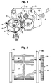
- the numeral 10 designates generally a frame which is conventional in rewinders. More particularly, the frame 10 includes a pair of longitudinally extending side frames 10a and 10b (see FIG. 2) which provide an elongated path and support a number of rotatable rolls therebetween.
- the numerals 11 and 12 at the upper left hand portion of the view designate pull rolls or draw rolls which operate to advance a web W from a parent roll (not shown).
- the web is further advanced by a perforator bedroll 13 and a transfer bedroll 14.
- Cross perforations as at W' are provided in the web -- see also FIGS. 3 and 4 --by a knife-equipped perforator bedroll 13 operating against a stationary anvil 15.
- the widely used perforator is seen in co-owned, expired Patent No. 2,870,840.
- the web in proceeding along the path P defined by the frame 10 is in partial wrapping relation to a bedroll 14.
- the numeral 16 designates the brush roll which operates as a backup roll in combination with the bedroll 14 for the cutoff and impalement of the free leading edge of the web W.
- the invention is described in conjunction with a "center-wound" type of rewinder, particularly of the type of Patent RE. 28,353.
- the invention can be used equally advantageously with surface wound types such as those seen in co-owned Patents No. 4,828,195 and 4,962,897, and earlier Patent No. 4,487,377.
- the numeral 17 designates generally a mandrel-equipped turret which is mounted for rotation in rewinder frame 10 and which is disposed in parallel, side-by-side relation with the bedroll 14.
- the turret 17 is equipped with six mandrels as at 18, the mandrels being arranged for sequential movement into web-contacting relation.
- a core on which the web W is to be wound is inserted on the mandrel 18 in the station designated by the letter A.
- a mandrel 18 is rotated from the core-receiving station A into the station B, where previously the core was slit to correspond to the axial length of toilet tissue or towel rolls. Now the cutting is performed on the completely rewound roll-termed a log.
- the station B is unused in current rewinders. Further rotation of the turret 17 brings a mandrel 18 to the station designated C where glue-applying mechanism operates to provide each core segment with glue between the stations C and D. Still further rotation of the turret moves the mandrel into the station D, where the new mandrel is accelerated to transfer speed preparatory to transfer. In the station D, the mandrel 18 is engaged with the driving belt 19 and is accelerated to web speed. As the mandrel moves toward station E transfer occurs.
- the mandrel 18 During movement from station E to station F, the mandrel 18 continues moving down and increasingly away from the bedroll 14. Prior to reaching station F, a discrete, predetermined length of the web has been wound and cut off, after which the mandrel arrives in position F, which is the finished roll-removing station.
- Finished roll removal is achieved through the mechanism seen in co-owned Patent 2,769,600.
- the intermittent operation of the turret 17 is achieved through a Geneva gear and other suitable mechanism (not shown), which indexes shaft 20.
- the mandrels 18 may be driven by a motor through the belt 19 previously described. Details of the belt drive can be seen in co-owned, expired Patent No. 3,116,890.
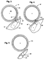
- the symbol W again designates the web but here in the process of being in contacted by the emergent means 21. These operate in conjunction with the brush roll 16 which is equipped with bristles protruding from a central core 22 as at 23.
- the emergent means includes a blade 24 which engages the web W at a line of cross perforations W' and results in a free leading edge W'' which is impaled on a pointed finger means 25. More particularly, a plurality of such fingers are employed aligned transversely of the rewinder so as to insure secure capture of the free leading edge W''. More particularly, in FIG. 3, the knife blade 24 is seen partially inserted into the bristles 23 to insure proper cutoff.
- the pointed finger means 25 are seen entering into the protruding bristles 23 of the brush roll 16' to make sure that this capture is achieved. After leaving the bristles 23 of the roll 16' the finger means 25 convey the leading edge W'' of the web W into contact with a core for the development of a new retail sized roll.
- FIG. 5 an alternative embodiment is illustrated where the pointed finger means are replaced by vacuum ports 125 in bedroll 114. There is however, the same emergent knife 124. Also, the details of the bristle-equipped anvil roll 116 is substantially the same as that of the embodiment illustrated in FIGS. 3 and 4.
- the bristle density is of the order of about 500-3000 per square inch with 1600 being optimum.
- the bristle diameter is of the order of about .005-.050 inch with .016 inch being optimum
- the bristle length is of the order of about 0.25-1.25 inch with 0.5 inch being optimum.
- the roll diameter (including protruberant bristles is of the order of about 5-20 inch with 7.5 inch being optimum.
- the surface speed of the brush roll can range from 15% to 20% below web speed to 15% to 20% above web speed. This avoids catching the web on the brush roll.
- the speed of the various rolls is advantageously achieved through drive means such as that depicted schematically in FIG. 2 where the numeral 26 designates generally a timing belt connecting a pulley on the shaft 27 of the bedroll 14 and a pulley on shaft 28 of the backup roll 16. These are conventionally driven by motor means (not shown).
- An advantage of the brush roll is that accuracy of gears is not needed.
Landscapes
- Life Sciences & Earth Sciences (AREA)
- Forests & Forestry (AREA)
- Engineering & Computer Science (AREA)
- Mechanical Engineering (AREA)
- Replacement Of Web Rolls (AREA)
- Advancing Webs (AREA)
- Measuring And Recording Apparatus For Diagnosis (AREA)
Applications Claiming Priority (2)
| Application Number | Priority Date | Filing Date | Title |
|---|---|---|---|
| US173493A | 1993-01-07 | 1993-01-07 | |
| US1734 | 1993-01-07 |
Publications (1)
| Publication Number | Publication Date |
|---|---|
| EP0607525A1 true EP0607525A1 (de) | 1994-07-27 |
Family
ID=21697567
Family Applications (1)
| Application Number | Title | Priority Date | Filing Date |
|---|---|---|---|
| EP93118680A Withdrawn EP0607525A1 (de) | 1993-01-07 | 1993-11-19 | Abtrenn- und Transfermechanismus für einen Umspuler |
Country Status (7)
| Country | Link |
|---|---|
| EP (1) | EP0607525A1 (de) |
| JP (1) | JPH0733296A (de) |
| AU (1) | AU5069393A (de) |
| BR (1) | BR9304868A (de) |
| CA (1) | CA2102937A1 (de) |
| MX (1) | MX9307245A (de) |
| ZA (1) | ZA938765B (de) |
Cited By (6)
| Publication number | Priority date | Publication date | Assignee | Title |
|---|---|---|---|---|
| WO2000047503A3 (en) * | 1999-02-09 | 2000-12-07 | Procter & Gamble | Web rewinder with chop-off and transfer assembly |
| US6805316B2 (en) | 2001-10-23 | 2004-10-19 | Kimberly-Clark Worldwide, Inc. | Apparatus for severing, carrying or winding a web |
| US6877689B2 (en) | 2002-09-27 | 2005-04-12 | C.G. Bretting Mfg. Co., Inc. | Rewinder apparatus and method |
| CN101966940A (zh) * | 2010-09-22 | 2011-02-09 | 浙江建达机械有限公司 | 气垫膜机自动点断装置 |
| EP3078464A4 (de) * | 2013-12-05 | 2017-08-30 | TKT Brainpower Engineering, S.L. | Schneidvorrichtung für flexibles material |
| CN107879187A (zh) * | 2017-12-19 | 2018-04-06 | 唐山市致富塑料机械有限公司 | 全自动微喷带收卷机 |
Citations (6)
| Publication number | Priority date | Publication date | Assignee | Title |
|---|---|---|---|---|
| GB599170A (en) * | 1945-09-14 | 1948-03-05 | Francis Joseph Connolly | Improvements relating to machines for cutting or perforating sheet material |
| US3128057A (en) * | 1962-06-12 | 1964-04-07 | Procter & Gamble | Double ply web transfer device |
| US3604302A (en) * | 1970-02-13 | 1971-09-14 | Dovey Mfg Co | Brush anvil |
| US3618436A (en) * | 1969-08-25 | 1971-11-09 | Donald A Brown | Brush surfaced anvil for rotary sheet-cutting equipment |
| USRE28353E (en) * | 1962-09-17 | 1975-03-04 | Web-winding apparatus and method | |
| US4487377A (en) * | 1981-08-26 | 1984-12-11 | Finanziaria Lucchese S.P.A. | Web winding apparatus and method |
-
1993
- 1993-11-12 CA CA002102937A patent/CA2102937A1/en not_active Abandoned
- 1993-11-15 AU AU50693/93A patent/AU5069393A/en not_active Abandoned
- 1993-11-19 EP EP93118680A patent/EP0607525A1/de not_active Withdrawn
- 1993-11-19 MX MX9307245A patent/MX9307245A/es unknown
- 1993-11-23 ZA ZA938765A patent/ZA938765B/xx unknown
- 1993-11-29 BR BR9304868A patent/BR9304868A/pt not_active Application Discontinuation
-
1994
- 1994-01-06 JP JP6000211A patent/JPH0733296A/ja active Pending
Patent Citations (6)
| Publication number | Priority date | Publication date | Assignee | Title |
|---|---|---|---|---|
| GB599170A (en) * | 1945-09-14 | 1948-03-05 | Francis Joseph Connolly | Improvements relating to machines for cutting or perforating sheet material |
| US3128057A (en) * | 1962-06-12 | 1964-04-07 | Procter & Gamble | Double ply web transfer device |
| USRE28353E (en) * | 1962-09-17 | 1975-03-04 | Web-winding apparatus and method | |
| US3618436A (en) * | 1969-08-25 | 1971-11-09 | Donald A Brown | Brush surfaced anvil for rotary sheet-cutting equipment |
| US3604302A (en) * | 1970-02-13 | 1971-09-14 | Dovey Mfg Co | Brush anvil |
| US4487377A (en) * | 1981-08-26 | 1984-12-11 | Finanziaria Lucchese S.P.A. | Web winding apparatus and method |
Cited By (9)
| Publication number | Priority date | Publication date | Assignee | Title |
|---|---|---|---|---|
| WO2000047503A3 (en) * | 1999-02-09 | 2000-12-07 | Procter & Gamble | Web rewinder with chop-off and transfer assembly |
| US6308909B1 (en) | 1999-02-09 | 2001-10-30 | The Procter & Gamble Company | Web rewinder chop-off and transfer assembly |
| US6488226B2 (en) | 1999-02-09 | 2002-12-03 | Mcneil Kevin Benson | Web rewinder chop-off and transfer assembly |
| US6805316B2 (en) | 2001-10-23 | 2004-10-19 | Kimberly-Clark Worldwide, Inc. | Apparatus for severing, carrying or winding a web |
| US6877689B2 (en) | 2002-09-27 | 2005-04-12 | C.G. Bretting Mfg. Co., Inc. | Rewinder apparatus and method |
| CN101966940A (zh) * | 2010-09-22 | 2011-02-09 | 浙江建达机械有限公司 | 气垫膜机自动点断装置 |
| EP3078464A4 (de) * | 2013-12-05 | 2017-08-30 | TKT Brainpower Engineering, S.L. | Schneidvorrichtung für flexibles material |
| US10183412B2 (en) | 2013-12-05 | 2019-01-22 | Tkt Brainpower Engineering, S.L. | Cutting device for flexible material |
| CN107879187A (zh) * | 2017-12-19 | 2018-04-06 | 唐山市致富塑料机械有限公司 | 全自动微喷带收卷机 |
Also Published As
| Publication number | Publication date |
|---|---|
| JPH0733296A (ja) | 1995-02-03 |
| MX9307245A (es) | 1994-07-29 |
| ZA938765B (en) | 1994-07-07 |
| CA2102937A1 (en) | 1994-07-08 |
| BR9304868A (pt) | 1994-07-26 |
| AU5069393A (en) | 1994-07-14 |
Similar Documents
| Publication | Publication Date | Title |
|---|---|---|
| US5421536A (en) | Surface winder with recycled mandrels and method | |
| US4529141A (en) | Method and apparatus for rewinding, severing and transferring web-like material | |
| RU2189347C2 (ru) | Перемотно-разрезной станок для изготовления рулонов из рулонного материала и способ изготовления рулонов | |
| EP1150912B1 (de) | Bahnwickler mit abtrenn- und übergabevoriichtung | |
| CA1310310C (en) | Method and apparatus for the automatic separation and winding of a material web | |
| US5497959A (en) | Coreless winding method and apparatus | |
| US5322230A (en) | Method and apparatus for preparing a replacement paper roll for flying roll change, particularly to supply paper to a rotary printing press | |
| CA2607168C (en) | Method and device for manufacturing rolls of web material with an outer wrapping | |
| CA1192532A (en) | Web winding apparatus and method | |
| EP0118384A1 (de) | Papierwickelmaschine mit Trennmesser | |
| KR100978080B1 (ko) | 오염물 제거 테이프 롤 형성 장치 및 오염물 제거 테이프롤 형성 방법 | |
| CA2306223C (en) | A roll rewinding apparatus | |
| CA2102937A1 (en) | Cutoff and transference mechanism for rewinder | |
| EP1724221B1 (de) | Vorrichtung zum Abschneiden einer Bahn in einem Umwickler | |
| JPS6128573B2 (de) | ||
| US20020117575A1 (en) | Apparatus and method for severing or separating a web | |
| US6230998B1 (en) | Method for transferring a web of material from a wound roll onto a winding tube, and winding apparatus | |
| EP0616965B1 (de) | Verfahren zum Aufwickeln von kernlosen Rollen | |
| JP2004255780A (ja) | ラベル巻回体の製造方法、ラベル巻回体の製造装置およびラベル巻回体 | |
| JPH101241A (ja) | 無芯ロールペーパーの製造方法及びその製造方法で使用される巻芯引出し装置 | |
| EP1040894B1 (de) | Schneidvorrichtung für Umwickelmaschine | |
| JPH0818733B2 (ja) | コア−ストリッパ− | |
| HK1028010A (en) | Slitter rewinder machine for producing reels of weblike material and associated method |
Legal Events
| Date | Code | Title | Description |
|---|---|---|---|
| PUAI | Public reference made under article 153(3) epc to a published international application that has entered the european phase |
Free format text: ORIGINAL CODE: 0009012 |
|
| AK | Designated contracting states |
Kind code of ref document: A1 Designated state(s): AT BE CH DE FR GB GR IT LI SE |
|
| 17P | Request for examination filed |
Effective date: 19940831 |
|
| STAA | Information on the status of an ep patent application or granted ep patent |
Free format text: STATUS: THE APPLICATION HAS BEEN WITHDRAWN |
|
| 18W | Application withdrawn |
Withdrawal date: 19960118 |