EP0607530A1 - Verbesserte Feststoffe-Gas-Trennvorrichtung und Verfahren - Google Patents
Verbesserte Feststoffe-Gas-Trennvorrichtung und Verfahren Download PDFInfo
- Publication number
- EP0607530A1 EP0607530A1 EP93118816A EP93118816A EP0607530A1 EP 0607530 A1 EP0607530 A1 EP 0607530A1 EP 93118816 A EP93118816 A EP 93118816A EP 93118816 A EP93118816 A EP 93118816A EP 0607530 A1 EP0607530 A1 EP 0607530A1
- Authority
- EP
- European Patent Office
- Prior art keywords
- chamber
- primary
- gas
- solid particles
- separation
- Prior art date
- Legal status (The legal status is an assumption and is not a legal conclusion. Google has not performed a legal analysis and makes no representation as to the accuracy of the status listed.)
- Withdrawn
Links
- 238000000034 method Methods 0.000 title claims abstract description 120
- 238000000926 separation method Methods 0.000 title claims abstract description 111
- 239000007787 solid Substances 0.000 claims abstract description 201
- 230000008569 process Effects 0.000 claims abstract description 94
- 239000002245 particle Substances 0.000 claims description 105
- JTJMJGYZQZDUJJ-UHFFFAOYSA-N phencyclidine Chemical class C1CCCCN1C1(C=2C=CC=CC=2)CCCCC1 JTJMJGYZQZDUJJ-UHFFFAOYSA-N 0.000 claims description 53
- 238000004891 communication Methods 0.000 claims description 21
- 238000012545 processing Methods 0.000 claims description 9
- 238000007599 discharging Methods 0.000 claims description 7
- 238000002485 combustion reaction Methods 0.000 claims description 6
- 230000005484 gravity Effects 0.000 claims description 5
- 230000007423 decrease Effects 0.000 claims description 4
- 238000004523 catalytic cracking Methods 0.000 claims description 3
- 239000011164 primary particle Substances 0.000 claims 1
- 239000003054 catalyst Substances 0.000 abstract description 64
- 239000007789 gas Substances 0.000 description 141
- 238000004231 fluid catalytic cracking Methods 0.000 description 33
- 238000013461 design Methods 0.000 description 15
- 238000005516 engineering process Methods 0.000 description 10
- 239000003546 flue gas Substances 0.000 description 10
- 238000011068 loading method Methods 0.000 description 9
- UGFAIRIUMAVXCW-UHFFFAOYSA-N Carbon monoxide Chemical compound [O+]#[C-] UGFAIRIUMAVXCW-UHFFFAOYSA-N 0.000 description 8
- 230000003247 decreasing effect Effects 0.000 description 6
- 238000005336 cracking Methods 0.000 description 5
- 239000012530 fluid Substances 0.000 description 5
- 239000002002 slurry Substances 0.000 description 5
- 230000009467 reduction Effects 0.000 description 4
- 230000000694 effects Effects 0.000 description 3
- 238000005243 fluidization Methods 0.000 description 3
- OKTJSMMVPCPJKN-UHFFFAOYSA-N Carbon Chemical compound [C] OKTJSMMVPCPJKN-UHFFFAOYSA-N 0.000 description 2
- 229910052799 carbon Inorganic materials 0.000 description 2
- 238000006243 chemical reaction Methods 0.000 description 2
- 239000000571 coke Substances 0.000 description 2
- 238000004939 coking Methods 0.000 description 2
- 230000007613 environmental effect Effects 0.000 description 2
- 230000006872 improvement Effects 0.000 description 2
- 238000009434 installation Methods 0.000 description 2
- 239000000203 mixture Substances 0.000 description 2
- KLSJWNVTNUYHDU-UHFFFAOYSA-N Amitrole Chemical compound NC1=NC=NN1 KLSJWNVTNUYHDU-UHFFFAOYSA-N 0.000 description 1
- 235000019738 Limestone Nutrition 0.000 description 1
- 230000002411 adverse Effects 0.000 description 1
- 230000003197 catalytic effect Effects 0.000 description 1
- 239000000567 combustion gas Substances 0.000 description 1
- 239000012141 concentrate Substances 0.000 description 1
- 238000010924 continuous production Methods 0.000 description 1
- 230000010485 coping Effects 0.000 description 1
- 238000011161 development Methods 0.000 description 1
- 230000018109 developmental process Effects 0.000 description 1
- 238000009792 diffusion process Methods 0.000 description 1
- 239000012717 electrostatic precipitator Substances 0.000 description 1
- 230000008030 elimination Effects 0.000 description 1
- 238000003379 elimination reaction Methods 0.000 description 1
- 230000003628 erosive effect Effects 0.000 description 1
- 238000010348 incorporation Methods 0.000 description 1
- 230000010354 integration Effects 0.000 description 1
- 239000006028 limestone Substances 0.000 description 1
- 239000000463 material Substances 0.000 description 1
- 238000005272 metallurgy Methods 0.000 description 1
- 238000012986 modification Methods 0.000 description 1
- 230000004048 modification Effects 0.000 description 1
- 239000012716 precipitator Substances 0.000 description 1
- 230000035755 proliferation Effects 0.000 description 1
- 238000000197 pyrolysis Methods 0.000 description 1
- 238000004064 recycling Methods 0.000 description 1
- 230000008929 regeneration Effects 0.000 description 1
- 238000011069 regeneration method Methods 0.000 description 1
- 230000003014 reinforcing effect Effects 0.000 description 1
- 238000007789 sealing Methods 0.000 description 1
- 230000008016 vaporization Effects 0.000 description 1
- 238000013022 venting Methods 0.000 description 1
- 239000002699 waste material Substances 0.000 description 1
Images



Classifications
-
- B—PERFORMING OPERATIONS; TRANSPORTING
- B01—PHYSICAL OR CHEMICAL PROCESSES OR APPARATUS IN GENERAL
- B01D—SEPARATION
- B01D45/00—Separating dispersed particles from gases or vapours by gravity, inertia, or centrifugal forces
- B01D45/12—Separating dispersed particles from gases or vapours by gravity, inertia, or centrifugal forces by centrifugal forces
-
- B—PERFORMING OPERATIONS; TRANSPORTING
- B01—PHYSICAL OR CHEMICAL PROCESSES OR APPARATUS IN GENERAL
- B01D—SEPARATION
- B01D45/00—Separating dispersed particles from gases or vapours by gravity, inertia, or centrifugal forces
- B01D45/04—Separating dispersed particles from gases or vapours by gravity, inertia, or centrifugal forces by utilising inertia
- B01D45/08—Separating dispersed particles from gases or vapours by gravity, inertia, or centrifugal forces by utilising inertia by impingement against baffle separators
-
- B—PERFORMING OPERATIONS; TRANSPORTING
- B04—CENTRIFUGAL APPARATUS OR MACHINES FOR CARRYING-OUT PHYSICAL OR CHEMICAL PROCESSES
- B04C—APPARATUS USING FREE VORTEX FLOW, e.g. CYCLONES
- B04C5/00—Apparatus in which the axial direction of the vortex is reversed
- B04C5/24—Multiple arrangement thereof
- B04C5/28—Multiple arrangement thereof for parallel flow
-
- C—CHEMISTRY; METALLURGY
- C10—PETROLEUM, GAS OR COKE INDUSTRIES; TECHNICAL GASES CONTAINING CARBON MONOXIDE; FUELS; LUBRICANTS; PEAT
- C10G—CRACKING HYDROCARBON OILS; PRODUCTION OF LIQUID HYDROCARBON MIXTURES, e.g. BY DESTRUCTIVE HYDROGENATION, OLIGOMERISATION, POLYMERISATION; RECOVERY OF HYDROCARBON OILS FROM OIL-SHALE, OIL-SAND, OR GASES; REFINING MIXTURES MAINLY CONSISTING OF HYDROCARBONS; REFORMING OF NAPHTHA; MINERAL WAXES
- C10G11/00—Catalytic cracking, in the absence of hydrogen, of hydrocarbon oils
- C10G11/14—Catalytic cracking, in the absence of hydrogen, of hydrocarbon oils with preheated moving solid catalysts
- C10G11/18—Catalytic cracking, in the absence of hydrogen, of hydrocarbon oils with preheated moving solid catalysts according to the "fluidised-bed" technique
Definitions
- This invention relates to a method and apparatus for the separation of entrained solid particles from a process gas stream, and more particularly to a fluidized catalytic cracking process employing such a method and apparatus.
- the fluid catalytic cracking (FCC) unit has been a main processing unit in oil refineries since the 1940's, when the first FCC process was commercialized. Since that time there have been many mechanical and technical improvements in the basic processing system and many processing variations based on fluidization of solid particles have been introduced and commercialized. An inherent problem in all fluidized systems is the control of the particulate effluent, which involves separating the fluidizing media (process gas) and the entrained solid particles.
- the original FCC units used small cyclones in the reactor system to separate reaction gases from solids (catalyst) entrained with the gas product from the reactor and returned the catalyst back to the process reactor bed.
- the FCC regenerator recycled solids (catalyst) back to the regenerator from an electrostatic precipitator, which was a principal separation means employed for separating entrained particulates from the regenerator flue gas before venting the flue gas to the atmosphere.
- the FCC type systems standardized on cyclones as the primary means of separating the circulating solids entrained with the gases from both the reactor and regenerator.
- the main problem in design of the cyclone systems for a FCC type system containing a reactor and regenerator is balancing the cyclone efficiencies. That is, the reactor cyclone(s) efficiency, as measured by the size of the particles removed, must be the same or slightly better in the reactor than in the regenerator, as the catalyst losses from the reactor are more difficult to handle than those from the regenerator.
- the efficiency of regenerator cyclones was improved by the reduction of the gas outlet tube size.
- this improvement in regenerator cyclone efficiency had an adverse effect on the losses from the reactor side and increased the amount of catalyst in the FCC slurry oil.
- Another critical consideration in the design of both the reactor and regenerator is to design the cyclone systems to maintain a certain particle size in order to maintain circulation and fluidization.
- FCC systems employing "U-bends" must operate with a lower Average Particle Size (APS), more in the less than 40 micron APS, than FCC systems that employ shorter and straighter standpipes.
- APS Average Particle Size
- the cyclones must have a minimum efficiency.
- the fresh catalyst supplied must be in a certain particulate size range, as well as meet certain diffusion (activity) and attrition criteria to function in the unit.
- the solution to reducing particulate emissions is not as easy as merely using a larger particle.
- FCC cyclone technology is employing external cyclones, but still uses bed rather than transport type two stage regeneration and riser type cracking in the reactor. This type of design has about the same capital requirements as locating the cyclones internally in the reactor and regenerator vessels.
- external cyclones the FCC units are much more difficult to design because each individual cyclone that was once located inside the reactor and regenerator now becomes a pressure vessel, and while the cyclone inlets and gas outlets can be manifolded, each of the cyclone diplegs must be returned to the vessel.
- a general objective to the present invention is to overcome the aforementioned and other related problems in prior art systems for separating particulates from process gas streams.
- a primary object of the present invention is a method and apparatus for controlling particulate emissions in a system employing a gaseous fluidizing media to transport particulate solids.
- Another object of the invention is an improved solids-gas separation system which achieves an increased efficiency of particulate removal from a fluidized solids process stream.
- Another object of the invention is a solids-gas separation system which enables decreased capital requirements when employed in a process unit using a gaseous fluidizing medium to transport particulate solids.
- Another object of the invention is an FCC or 3D type (as hereinafter described) processing system which utilizes only one stage cyclones, as compared to current state of the art processing systems utilizing two stages of cyclones, to achieve a very low level of particulate solids in regenerator flue gases exhausted to the atmosphere and/or in reactor effluent vapors.
- the present invention utilizes only one stage of cyclones, as compared with the current state of the art which utilizes two stages of cyclones, and results in decreased capital requirements and an increased particulate removal efficiencies when applied to both the reactor and regenerator systems of an FCC type or 3D type (as hereinafter described) processing systems.
- This invention is best utilized on fluidized combustion devices, such as fluid cokers, FCC regenerators, ART burners, 3D regenerators, or fluidized bed boilers, where one contacts a fluidized solid with combustion air and maintains a fluidized bed, or transport solid systems where the solids and combustion gases must be separated before releasing the flue gases to the atmosphere. It is also applicable to FCC type reactor systems including bed, riser or MSCC (as hereinafter described) type systems to separate the reactor effluent vapors from the entrained catalyst.
- an apparatus for separating particulate solids from a process gas stream comprises a ballistic separation chamber comprising: a first chamber portion having a first end portion in which there is positioned an inlet means for introducing thereinto a process gas stream containing entrained solid particles; a second chamber portion joined to and in flow communication with the first chamber portion so as to provide in the chamber a flow path extending from the inlet means toward a second end portion, the second chamber portion having a cross sectional flow area greater than that of the first chamber portion and having the second end portion spaced downstream from the junction of the first and second chamber portions; solid particle outlet means positioned in the second chamber portion intermediate the junction and the second end portion for removing therefrom a stream rich in separated solid particles; gas outlet means positioned in the separation chamber intermediate the inlet means and the solid particle outlet means for removing therefrom a stream rich in process gas; and baffle means arranged in the separation chamber between the inlet means and the gas outlet means for
- apparatus for separating particulate solids from a process gas stream comprises: a primary inlet means for introducing into the apparatus a process gas stream containing entrained solid particles received from a source vessel; a primary ballistic separation chamber in flow communication with the primary inlet means for receiving the gas stream and entrained solid particles introduced thereinto and effecting therein a ballistic separation of a major portion of the solid particles from the process gas; the primary separation chamber comprising (1) a first chamber portion having a first end portion in which the primary inlet means is positioned and (2) a second chamber portion joined to and in flow communication with the first chamber portion, having a cross sectional flow area greater than the of the first chamber portion and positioned downstream from the primary inlet means; a secondary separator chamber for receiving a process stream containing a minor portion of the solid particles from the second chamber portion, the secondary separator chamber having a secondary inlet means providing direct flow communication between the secondary separator chamber and the second chamber portion; a plurality of cyclone separator
- the above ballistic, or primary, separator chamber is an elongated, generally horizontal vessel which is curved along its longitudinal axis to provide an arcuate flow path so as to enable the utilization of centrifugal force to further enhance the efficiency of the gas-solids separation therein.
- Such an arrangement facilitates the incorporation of the apparatus of the invention into existing vessels of a processing unit since the primary separator length and diameter can conform to a circular vessel, while improving the efficiency of separation, facilitating the designs and layout either inside or outside of a process vessel and enabling the use of preferred straight lines for returning the separated solid particles to a source vessel.
- Another preferred embodiment of the invention provides an apparatus for separating entrained particulate solids from a fluidizing gas, which apparatus comprises primary separation means for separating a major portion of the entrained solids from the gas and producing an upwardly flowing primary separated gas containing a remaining minor portion of the entrained solids, and secondary separation means positioned above the primary separation means for receiving the primary separated gas, removing substantially all of the remaining solids from the primary separated gas and producing an off-gas having a reduced solids content, the secondary separation means including, an off-gas collector housing having an off-gas outlet for discharging the gas substantially free of the solids, a plurality of secondary separation chambers each having a secondary gas inlet for receiving said primary separated gas, a secondary gas outlet in flow communication with the off-gas collector housing and a secondary solids outlet for discharging therefrom substantially all of the remaining solids, and multiple cyclonic separators in each of the secondary separator chambers for effecting the separation of the remaining solids from the primary separated gas
- the off-gas collector housing is cup
- a purpose of the present invention is to permit the ultimate use in the 3D and MSCC process technologies of a unique catalyst/solid separation system in the regenerator and reactor that will enable a reduction in the size of both the reactor and regenerator vessels and the elimination of one complete stage of cyclones.
- This unique system will also enable the reduction of the number of catalyst return pipes to three for any size unit, compared to conventional technology using one dipleg per cyclone for return of the particulates to the process vessel, when utilizing external cyclones, greatly reduces the complexity of design and lowers the capital investment.
- This same unique system is also useful in the reactor and enables increased efficiency of both the reactor and regenerator; when compared to today's state of the art. This will translate into lower particulate emissions from both the reactor and regenerator of these and other fluidized solids systems.
- the 3D Process employed for upgrading residual oil or heavy crudes, utilizes the asphaltene molecule in the feed as the source of energy for vaporizing the feed. Therefore, the coke yield is usually equal to or less than the Conradson Carbon in the feed. If one were to design a 3D unit to process 50,000 BPD of Maya crude containing 10% Conradson Carbon in a conventional manner (i.e. a regenerator containing two stages of conventional cyclones), the regenerator diameter would need be about 70 feet to accommodate at least 16 sets of the largest two stage cyclones (68 inch diameter barrels) produced. If these same cyclones were placed outside the unit as pressure vessels, the regenerator diameter would still need to be about 50 feet to accommodate all of the dipleg returns. However, if one designed this same system as described in the above patents the regenerator diameter would be about 20 feet. This latter size would not permit the use of conventional cyclone technology.
- the present invention provides a novel and continuous process and apparatus useful, e.g., in an FCC process for separating the regenerator flue gas from the particulates in the flue gas and returning the particulates to the circulating inventory.
- the present invention involves a primary separation of the particulate solids from the vapors based upon horizontal ballistic separation of the particles from the vapors prior to the vapors entering a secondary cyclone-type separation device.
- the secondary separation device is based upon the use of a multiple of small cyclones which are larger than those used in the Europis third stage cyclone described in U.S. Pat. No. 4,348,215 but smaller than those used in commercial FCC reactor and regenerator systems.
- Fig. 1 depicts the use of the present invention in an external system near the top of a transport riser, but one skilled in the art will realize that the system of the present invention may be installed inside another vessel as shown in Fig. 2 if so desired. Also, the embodiment shown in Fig. 1 may be installed in another vessel which houses conventional vertical cyclones where the gas outlet of the present invention is upward and not directly connected to the vertical cyclones.
- a fluidized mixture of effluent process gas and entrained catalyst/solids flows upwardly and exits the upper portion of a source vessel 10, e.g., a riser reactor of an FCC unit through a line 12, which may be either horizontal or vertical.
- the catalyst/solids entrained in the effluent process gas can be either the total catalyst/solids circulation, entrained material from a fluidized bed or from a previous stage of separation or a mixture of these as might be the case in multiple vessels.
- the preferred method is to employ a horizontal primary ballistic separation chamber 14, but those skilled in the art will realize that a vertical system will also perform almost as well and the actual configuration may be dictated by mechanical considerations.
- the primary ballistic separation chamber 14 comprises a first chamber portion 16 and a second chamber portion 18 positioned downstream of the first chamber portion.
- the primary separation chamber 14 may extend generally horizontal, slope downwardly (so that incoming solids flow downwardly toward the primary solids outlet 26) or extend downwardly, but it should not be positioned so that the incoming solid particles flow upwardly.
- the second chamber portion is joined to and in flow communication with the first chamber portion which has a first end portion 20 in which is positioned a primary inlet means 22, such as an opening, connected to line 12 for introducing a stream of fluidized solid particulates and process gas into the chamber 14.
- the solids/gas stream preferably contains not more than about 7, and most preferably contains from about 0.3 to about 5.0 pounds of solid particles per cubic foot of gas.
- the fluidized solids/gas stream is introduced into the first chamber portion at a velocity of from about 40 to about 200, and preferably from about 70 to about 120, feet per second .
- the first and second chamber portions are elongated vessels in flow communication with each other to provide, a flow path in the chamber 14 extending from the primary inlet 22 toward a second end portion 24 of the second chamber portion 22 which is located downstream from the junction 21 of the first and second chamber portions at a distance sufficient to permit a major portion of the entrained solid particles to separate in the second chamber portion from the solids/gas stream.
- the second chamber portion 18 has a cross-sectional flow area sufficiently greater than that of the first chamber portion 16 so the velocity of the solids/gas stream flowing in the second chamber portion is reduced to a level at which, in combination with the distance from the junction of the two chamber portions to the second end portion, a major portion, preferably at least about 80%, of the entrained solids separate from the solids/gas stream as it passes through the second chamber portion.
- the second chamber portion is provided in a lower portion thereof with a primary solid particle outlet means 26, such as an opening in the bottom of the chamber, for withdrawing therefrom a stream rich in separated solid particles for return to the process source through line 28, e.g., a dip-leg, connecting the solids outlet means 26 and the process source vessel, e.g., an FCC unit regenerator.
- a primary solid particle outlet means 26 such as an opening in the bottom of the chamber
- the dip-leg 28 extends into a lower portion of FCC regenerator 30
- the lower end of the dip-leg extends into the regenerator catalyst bed 32 and its lower end is sealed by, e.g., a vertical flapper valve 34 or a horizontal counter weighted valve.
- the solid particle outlet means 26 is positioned intermediate the junction of the first and second chamber portions 16 and 18 and the second end portion 24 and spaced from the second end portion at a distance which permits the separated particulates to fall to the bottom of the second chamber portion near the second end portion and flow by gravity through the primary solid particle outlet means 26 into solids withdrawal line 28.
- the cross sectional flow area of the inlet (the upper portion) of line 28 preferably is larger, most preferably at least about 10 times larger, than the cross-sectional flow area of the lower portion of line 28 to aid in de-gassing the downwardly flow solids.
- the second chamber portion 18 is also provided with a gas outlet means 36 positioned in the chamber 14 adjacent the junction 21 and intermediate the primary solids/gas inlet 22 and the primary solid particle outlet opening 26, for withdrawing from chamber 14 a stream rich in process gas and from which solids have been separated and passing the gas-rich stream to a secondary separation chamber 38 wherein a further solids-gas separation is effected as described hereinbelow.
- the second chamber portion 18 may be positioned above the first chamber portion 16 with the gas outlet means 36 in the top of the chamber 14, it is sometimes preferred that the second chamber portion be below the first chamber portion and the gas outlet means be positioned in the bottom thereof, as shown in Fig. 1, since the latter arrangement results in greater efficiency.
- a baffle means 40 be arranged in the primary separation chamber 14 between the primary inlet 22 and the primary gas outlet 36 for directing the solids/gas stream from the first chamber portion past the primary gas outlet 36, so that the heavier solid particles are "shot” past the gas outlet toward the second end portion 24 and can separate from the stream in the second chamber portion 18, and the resulting stream containing a reduced amount of solid particles passes through the gas outlet 36 and into the secondary separation chamber 38.
- the primary inlet 22 is taken from the opposite side of the baffle 40. Also, the actual location of the secondary separation chamber relative to the primary separation chamber is not critical (i.e. it is the outlet from the primary separation chamber which is important). The secondary chamber can be located at any convenient position.
- the ballistic separation chamber 14 may be a vertical chamber wherein the primary solids/gas inlet means 22 is positioned above the vertically extending first and second chamber positions 16 and 18.
- the baffle 40 extends downwardly past the gas outlet means 36 and intermediate the primary inlet means 22 and the primary gas outlet 36.
- a major portion of the entrained solids passes downwardly, past baffle 40, through the second chamber portion 18 and exists the chamber 14 through solid particle outlet means 26 at the lower end of chamber 14, which a stream rich in process gas and from which solids have been separated passes upwardly on the side of baffle 40 opposite inlet means 22 and exists the chamber 14 through the primary gas outlet 36.
- Figure 4 illustrates a preferred embodiment of the "ballistic separator” wherein, to increase the separation efficiency, ballistic separation is combined with centrifugal separation.
- This system uses centrifugal separation to force the particulates/solids entering with the process gas into primary inlet 22 from line 12 to concentrate at the outer wall in primary separator 14, in both the first chamber portion 16 and the second chamber portion 18, so that less solids will be entrained in the gas exiting on the inside radius of primary separator 14 through gas outlet 36 and into secondary separator chamber 38 through secondary inlet 42.
- the system shown in Figure 4 is especially preferred as it is easy to incorporate into existing vessels since the primary separator 14 length and radius can be conformed to a circular vessel, it will be much more efficient than the straight horizontal system shown in Figs. 1-3, and it will be easier to design and layout either inside or outside of a vessel and easier to maintain straight solids return lines to the process, which is preferable.
- the secondary separation chamber 38 is provided with a secondary gas inlet 42 in the top portion which is in flow communication with the primary gas outlet 36 of the primary chamber 14.
- Process gas and the remaining entrained catalyst pass through inlet 42 and enter horizontal cyclones 46 on the interior of secondary separation chamber 38 which separate substantially all of the remaining entrained solids from the process gas.
- the solids/gas stream entering gas inlet 42 contains a minor portion of the total solids entrained in the solids/gas stream from line 12 and, preferably not more than about 0.5 pounds of solid particles per cubic foot of the solids/gas stream.
- the off-gas stream cleansed by cyclones 46 of substantially all of the solid particles and preferably containing not more than about 0.0005 pound of solid particles per cubic foot, exits the secondary separation chamber 38 through off-gas outlet 48 connected to vent line 50 which vents the off-gas to the atmosphere.
- the separated solids are collected and discharged from chamber 38 into return line 44 and returned to the source vessel 30.
- the multi-cyclone (multi-clone) system depicted in Fig. 5 is a Cytrol Separator which is available from EMTROL Corp. of Hauppauge, NY; however, other multi-clone systems such as the aforementioned Europis cyclones may be used in the secondary separator.
- the number of cyclones 46 used in secondary separation chamber 38 will depend on the volumetric flow rate and the diameter of the cyclones will vary to match existing cyclone efficiencies. For systems that are stand alone like fluidized bed boilers and lime stone scrubbers, the diameter of the cyclones will be less than 10 inches for maximum efficiency. For systems that need to match another cyclone system such as an FCC reactor utilizing conventional cyclones, the cyclone(s) diameter will be between 8 and 67 inches, depending on the whether the reactor utilizes single stage or two stage cyclones and their efficiency.
- the multi-clone system shown in Fig. 5 is designed for catalyst solids loadings of 0.0001 pound per actual cubic foot of gas. As the diameter is increased to approximately 24 inches, this loading can be increased to from about 0.15 to 0.50 pound per cubic foot without flooding. Therefore, the primary separation chamber should be able to decrease the typical FCC regenerator or reactor gas loading from a normal 1 to 2 pounds per actual cubic foot of gas to a range which will not flood the smaller cyclones. This requires that the first chamber portion 16 velocity probably be greater than 40 fps and less than 200 fps.
- the internal baffle 40 should be equal to or extend downstream along the flow path slightly past primary gas outlet 36 to prevent short circuiting of the gas flow.
- the distance from the end of the baffle 40 to the intersection of the primary solids outlet 26 should be a minimum of one pipe diameter, with a three pipe diameter distance preferred.
- the length of the second end portion 24 should be a minimum of one pipe diameter, i.e., the diameter of the second chamber portion 18, with 1.5 diameters preferred.
- the final clean up of the process gas is accomplished in multi-clone system which, in a preferred embodiment are installed (horizontally, consists of cyclones up to 35 inches in diameter to match the efficiency of the other cyclones in the processing circuit.
- the treated process gas exits the secondary separator vessel 38 through secondary gas outlet 48 connected to off-gas line 50.
- the separated catalyst from the cyclones in secondary separator 38 exits by gravity from the bottom of the separator through lines 44 and 44' to return to the process.
- the system in accordance with the present invention will easily handle upsets in solids loading because of the increased stability offered by the inclusion of the first chamber portion 16 and the second chamber portion 18 in the primary separator 14.
- Figure 1 shows the installation of the system external to the process vessel and integrated into a fluid system as described for the regenerator in the above-mentioned 3D and MSCC patents. This external system could also be used on fluidized bed as shown in Figure 2 by returning the three catalyst return lines back to the bed with external connections.
- Figure 2 shows the integration of the system into a typical dense bed regenerator system or a reactor system, which could be a riser cracking system, a MSCC type system or another fluid bed system.
- the separator can be located either internal or external to the process vessel.
- the separator is assumed to be located external to vessel 10 as shown in Figure 1.
- Vessel 10 is a transport type riser system.
- the 100,000 acfm of fluidizing gas and particles exits vessel 10 through conduit 12, which is normally circular, but for low pressure operations could be a square or rectangular duct.
- the particulate laden gas enters primary separator 14, through first chamber portion 16, an upper circular conduit which is 55 inches ID and 150 inches long. This length includes baffle 40.
- the particles exiting the first chamber portion are propelled into the second chamber portion 18, the larger end of the primary separator 14 (80 inch ID) with such a forward force that they are not entrained with the gas as it turns to exit the primary separator through primary gas outlet 36 and secondary separator inlet 42, which is at least 55 inches ID.
- the particles are propelled past conduit 28, which is located 120 inches from the outlet of first chamber portion 16 and is 47 inches ID, into second chamber portion 18, which is 100 inches long and 80 inches ID, where the particulates deposit and flow by gravity into return pipe 28.
- the gas and residual particles entering multi-cyclone inlet 42 flow downward into secondary separation chamber 38, which houses the cyclones.
- the size of this vessel will depend on the type, number, and layout of the cyclones. For a unit employing a multiplicity of essentially horizontal cyclones, this vessel would be about 200 inches ID and 540 inches long.
- the particulates separated from the gas exits vessel 38 through conduit 44, which is 47 inches ID, and the essentially particulate free gas exits vessel 38 through secondary gas outlet 48 and line 50, which is 55 inches ID.
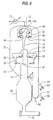
- FIGs. 6 and 7 Another especially preferred embodiment of the present invention is shown in Figs. 6 and 7 wherein one or more, preferably a plurality of the above-described ballistic separation chambers 14 are installed adjacent the upper end of a vertically extending transport riser 10 which may be either internal or external of a process vessel.
- gas and entrained solids flow upwardly in, for example, a fluid bed reactor or regenerator, and pass from the upper portion thereof into the primary inlet of each of a plurality of ballistic separation chambers 14 circumferentially spaced around the shell of the riser and radially intending therefrom.
- a major portion of the entrained particulate solids is separated as described hereinabove in chambers 14 and passed downwardly from the bottoms of the chambers, for return to the source vessel, while the gas and remaining entrained solids are passed upwardly from the tops of the chambers 14 for passage into cyclones from which the substantially solids-free off-gas is discharged to the atmosphere, and the separated solids are returned to the source vessel.
- the cyclones may be of the conventional type, for example conventional two-stage large vertical-type cyclones, or horizontal or vertical small multi-cyclones may be used.
- FIG. 6 for the purpose of exemplification, there is depicted this latter embodiment of the invention for use in a catalyst regenerator of a MSCC cracking unit, although it is to be understood that it may also be used in FCC reactors and other fluidized bed process units.
- Combustion air and spent catalyst from an FCC reactor flows through transport line 52, into the bottom portion of regenerator 54 and upwardly in regenerator 54.
- Carbonaceous deposits on the catalyst particles are burned off in the transport line and regenerator to regenerate the catalyst and restore its activity so that the regenerated catalyst may be returned to the reactor for further use.
- Hot catalyst particles, combustion air and combustion products rise in the regenerator, into regenerator riser 10 extending upwardly from the main body of the regenerator, and to the top-most portion of the riser where the gas and entrained solids enter primary inlet means 22 into each of primary ballistic separator chambers 14.
- regenerator riser 10 extending upwardly from the main body of the regenerator, and to the top-most portion of the riser where the gas and entrained solids enter primary inlet means 22 into each of primary ballistic separator chambers 14.
- In chambers 14 a major portion of the entrained solids is separated from the gas, as described with respect to Figs. 1-3 and discharged from chambers 14 through primary solid particle outlet means 26 positioned in the bottoms of each of chambers 14 and into solids withdrawal line 28 extending downwardly from chamber 14.
- Line 28 preferably has a cross-sectional flow area at its upper end connected to primary solids outlet 26 which about 10 times the cross-sectional flow area of the lower end to aid in de-gassing the separated catalyst passing downwardly in line 28.
- Each line 28 serves as a dipleg and is sealed at the bottom with a counter-weighted flapper valve 34 which permits the separated regenerated catalyst to drop into a lower region of regenerator cyclone vessel 56 which encloses the separation system positioned at the top end portion of regenerator riser 10, while preventing gas in vessel 56 from flowing into chambers 14.
- the separated regenerated catalyst then passes into a stripper section 58 and flows downwardly therein where it is stripped of entrained flue gas with steam introduced through line 60. Stripped regenerated catalyst is then returned to the reactor at one or more locations through lines 61, 61' and slide valves 62, 62'.
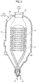
- Separated gas containing a minor portion of the entrained catalyst is discharged from each of chambers 14 through primary gas outlet means 36 positioned in the upper portion of chamber 14 into the upper portion of cyclone vessel 56 from which the gas and solids flow into the preferred embodiment of an internal secondary separator as shown in Figure 6 and detailed in Figure 7.
- This unique system is much different then the Europis or EMTROL system depicted in Figure 5 in that this multi-cyclone system is incorporated inside an operating process vessel 56, not a separate vessel, the gas inlet is from the bottom and in complete flow communication with the level in the bottom of vessel 56, there is only one catalyst/solids outlet line 44, and the annular area around the off-gas collector housing 66 and the body of the catalyst outlet vessel 64 decreases from the bottom to the top of vessel 64.
- the gas and solids from the primary separator enter the secondary separator from the bottom and flow upwardly into the gas inlets 42 of a plurality of horizontal multi-cyclones 46, of the type described hereinabove, for removing substantially all of the remaining entrained catalyst from the flue-gas.
- the cleansed flue gas exits the secondary separator through multi-cyclone outlets 48 for discharge to the atmosphere through off-gas collector housing 66 and off-gas outlet 68 connected to flue gas line 50.
- the catalyst separated in the secondary separator exits the multi-cyclones 46 through catalyst discharge opening 69 into catalyst outlet vessel 64.
- Off-gas collector housing 66 which has the form of an inverted cup, is positioned over the top of vessel 64 and has vertical walls extending downwardly around the body of catalyst outlet vessel 64.
- the top head of vessel 64 also forms the inner wall of the top portion of housing 66, and the outer wall of such top portion is provided with an off-gas outlet 68 connected to off-gas line 50.
- a plurality of horizontal multi-cyclones 46 are spaced around the circumference of catalyst outlet vessel 64 at one or more elevations along the height of vessel 64.
- Each multi-cyclone is provided with a secondary gas inlet 42 on the bottom thereof, a secondary gas outlet means 48 in flow communication with the interior of housing 66 and a secondary solids outlet 69 in flow communication with the interior of catalyst outlet vessel 64.
- multi-cyclones 46 are arranged horizontally, and gas outlets 48 and solid outlets 69 are positioned at opposite ends of cyclones 46.
- the separated gas containing a minor amount of the total entrained solids exits from primary gas outlets 36, rises in cyclone vessel 56 and flows through multi-cyclone inlets 42 into multi-cyclones 46 which separate substantially all of the remaining entrained solids from the gas.
- the thus-cleansed gas flows horizontally through secondary gas outlets 48 into gas collector housing 66, rises and exits through off-gas outlet 68 into off-gas line 50, after which it may be cooled by heat-exchange 70.
- Separated solids are discharged horizontally from cyclones 46 through solids outlets 69 and pass to the interior of catalyst outlet vessel 64 wherein they fall to the bottom thereof and pass downwardly through dipleg 44 and flapper valve 34' into a lower region of regenerator cyclone vessel 56.
- flapper values 34 and 34' are at the same elevation.
- the latter-described arrangement of the secondary separation system is especially advantageous for enabling the use of multi-cyclones in new or existing vessels that contain a fluid bed or transport line riser system that terminates in a rough cut fluidized solids separation device which reduces the catalyst loading to the multi-cyclones to less than about 0.5 pounds per cubic foot of gas.
- cyclones of 20 inches diameter or more the catalyst attrition is greatly reduced, while retaining higher separator efficiency than for conventional separation technology.
- the internal diameter (ID) of this upper vessel would be about 34 feet, with a tangent-to-tangent (T-T) length of about 45 feet.
- the catalyst regenerator ID can be decreased to about 23 feet and its T-T length can be decreased to about 36 feet.
- the T-T length can be reduced from about 45 feet to about 24 feet, while maintaining a reactor diameter about the same as that of a unit using conventional separation technology.
- use of the present invention permits better separation efficiency and more capacity in an existing FCC unit or lower cost in a new FCC unit.
Landscapes
- Chemical & Material Sciences (AREA)
- Chemical Kinetics & Catalysis (AREA)
- Oil, Petroleum & Natural Gas (AREA)
- Engineering & Computer Science (AREA)
- General Chemical & Material Sciences (AREA)
- Organic Chemistry (AREA)
- Devices And Processes Conducted In The Presence Of Fluids And Solid Particles (AREA)
Applications Claiming Priority (2)
| Application Number | Priority Date | Filing Date | Title |
|---|---|---|---|
| US981301 | 1993-01-21 | ||
| US07/981,301 US5286281A (en) | 1993-01-21 | 1993-01-21 | Solids-gas separation apparatus and method |
Publications (1)
| Publication Number | Publication Date |
|---|---|
| EP0607530A1 true EP0607530A1 (de) | 1994-07-27 |
Family
ID=25528281
Family Applications (1)
| Application Number | Title | Priority Date | Filing Date |
|---|---|---|---|
| EP93118816A Withdrawn EP0607530A1 (de) | 1993-01-21 | 1993-11-23 | Verbesserte Feststoffe-Gas-Trennvorrichtung und Verfahren |
Country Status (3)
| Country | Link |
|---|---|
| US (1) | US5286281A (de) |
| EP (1) | EP0607530A1 (de) |
| CA (1) | CA2103188A1 (de) |
Families Citing this family (5)
| Publication number | Priority date | Publication date | Assignee | Title |
|---|---|---|---|---|
| US5518695A (en) * | 1994-11-10 | 1996-05-21 | Uop | Vented riser with compact multiple cyclone arrangement |
| US5665130A (en) * | 1996-01-18 | 1997-09-09 | Natural Resources Canada | Riser terminator for internally circulating fluid bed reactor |
| WO2000027538A1 (en) * | 1998-11-06 | 2000-05-18 | Shell Internationale Research Maatschappij B.V. | Separator apparatus |
| US7329309B2 (en) * | 2004-12-22 | 2008-02-12 | Exxonmobil Chemical Patents Inc. | Gas-solids separation device and method |
| CN116329087B (zh) * | 2023-04-03 | 2025-09-23 | 中国烟草总公司郑州烟草研究院 | 一种柔性风选装置及柔性风选方法 |
Citations (5)
| Publication number | Priority date | Publication date | Assignee | Title |
|---|---|---|---|---|
| US4066533A (en) * | 1975-03-24 | 1978-01-03 | Ashland Oil, Inc. | Separation of catalyst from effluent of a fluidized catalytic hydrocarbon conversion process |
| US4285706A (en) * | 1979-03-20 | 1981-08-25 | Dehne Manfred F | Particulate filtration device |
| US4348215A (en) * | 1981-01-09 | 1982-09-07 | Dehne Manfred F | Particulate separation device |
| US4364905A (en) * | 1979-11-23 | 1982-12-21 | Standard Oil Company (Indiana) | Fluid catalytic cracking apparatus having riser reactor and improved means associated with the riser reactor for separating cracked product and entrained particulate catalyst |
| US4678642A (en) * | 1985-01-10 | 1987-07-07 | Ashland Oil, Inc. | Ballistic separation of particles in a progressive flow reactor |
Family Cites Families (5)
| Publication number | Priority date | Publication date | Assignee | Title |
|---|---|---|---|---|
| US3765153A (en) * | 1970-10-26 | 1973-10-16 | J Grey | Apparatus for removing contaminants entrained in a gas stream |
| US3873283A (en) * | 1973-07-02 | 1975-03-25 | Universal Oil Prod Co | Vapor-liquid separator |
| US4859315A (en) * | 1987-11-05 | 1989-08-22 | Bartholic David B | Liquid-solid separation process and apparatus |
| US4985136A (en) * | 1987-11-05 | 1991-01-15 | Bartholic David B | Ultra-short contact time fluidized catalytic cracking process |
| US5221301A (en) * | 1992-10-28 | 1993-06-22 | Emtrol Corporation | Multi-stage cyclone separator system with intermediate manifold |
-
1993
- 1993-01-21 US US07/981,301 patent/US5286281A/en not_active Expired - Fee Related
- 1993-11-16 CA CA002103188A patent/CA2103188A1/en not_active Abandoned
- 1993-11-23 EP EP93118816A patent/EP0607530A1/de not_active Withdrawn
Patent Citations (6)
| Publication number | Priority date | Publication date | Assignee | Title |
|---|---|---|---|---|
| US4066533A (en) * | 1975-03-24 | 1978-01-03 | Ashland Oil, Inc. | Separation of catalyst from effluent of a fluidized catalytic hydrocarbon conversion process |
| US4070159A (en) * | 1975-03-24 | 1978-01-24 | Ashland Oil, Inc. | Apparatus for separating solid dispersoids from gaseous streams |
| US4285706A (en) * | 1979-03-20 | 1981-08-25 | Dehne Manfred F | Particulate filtration device |
| US4364905A (en) * | 1979-11-23 | 1982-12-21 | Standard Oil Company (Indiana) | Fluid catalytic cracking apparatus having riser reactor and improved means associated with the riser reactor for separating cracked product and entrained particulate catalyst |
| US4348215A (en) * | 1981-01-09 | 1982-09-07 | Dehne Manfred F | Particulate separation device |
| US4678642A (en) * | 1985-01-10 | 1987-07-07 | Ashland Oil, Inc. | Ballistic separation of particles in a progressive flow reactor |
Also Published As
| Publication number | Publication date |
|---|---|
| CA2103188A1 (en) | 1994-07-22 |
| US5286281A (en) | 1994-02-15 |
Similar Documents
| Publication | Publication Date | Title |
|---|---|---|
| AU698978B2 (en) | Reduced chaos cyclone separation | |
| US7247233B1 (en) | Apparatus and process for minimizing catalyst residence time in a reactor vessel | |
| EP0760077B1 (de) | Verfahren zum katalytischen cracken im wirbelbett und vorrichtung enthaltend einen vortex in der dritten trennstufe | |
| EP0595132A2 (de) | Mehrstufiger Zyklonalscheider mit zwischenliegender Verteilkammer | |
| US7985282B2 (en) | Apparatus and method for separating solids from gas streams | |
| EP1133538B1 (de) | Trennungsgerät | |
| US5643537A (en) | FCC process and apparatus with contained vortex third stage separator | |
| US7799286B2 (en) | Stripping apparatus | |
| MXPA01008445A (es) | Proceso de separacion gas-solido. | |
| US8128807B2 (en) | FCC separator without a reactor | |
| US7914610B2 (en) | Stripping process | |
| US5286281A (en) | Solids-gas separation apparatus and method | |
| US5565020A (en) | Process and arrangement for separating particulate solids | |
| US5110323A (en) | Process for the return of recovered particulate solids by a cyclone separator to a vessel | |
| US20090107884A1 (en) | Stripping apparatus and process | |
| US6830735B1 (en) | Separator apparatus | |
| US5037617A (en) | Apparatus for the return of particulate solids through a cyclone separator to a vessel | |
| CN1798823B (zh) | 分离装置 | |
| CA2222597C (en) | Reduced chaos cyclone separation |
Legal Events
| Date | Code | Title | Description |
|---|---|---|---|
| PUAI | Public reference made under article 153(3) epc to a published international application that has entered the european phase |
Free format text: ORIGINAL CODE: 0009012 |
|
| AK | Designated contracting states |
Kind code of ref document: A1 Designated state(s): BE DE ES FR GB IT NL |
|
| 17P | Request for examination filed |
Effective date: 19940824 |
|
| 17Q | First examination report despatched |
Effective date: 19951102 |
|
| GRAG | Despatch of communication of intention to grant |
Free format text: ORIGINAL CODE: EPIDOS AGRA |
|
| STAA | Information on the status of an ep patent application or granted ep patent |
Free format text: STATUS: THE APPLICATION IS DEEMED TO BE WITHDRAWN |
|
| 18D | Application deemed to be withdrawn |
Effective date: 19961128 |