EP0607561A2 - Récepteur pour traiter des signaux de télévision transmis selon la méthode letterbox - Google Patents
Récepteur pour traiter des signaux de télévision transmis selon la méthode letterbox Download PDFInfo
- Publication number
- EP0607561A2 EP0607561A2 EP93119949A EP93119949A EP0607561A2 EP 0607561 A2 EP0607561 A2 EP 0607561A2 EP 93119949 A EP93119949 A EP 93119949A EP 93119949 A EP93119949 A EP 93119949A EP 0607561 A2 EP0607561 A2 EP 0607561A2
- Authority
- EP
- European Patent Office
- Prior art keywords
- luminance signal
- circuit
- memory
- color difference
- signals
- Prior art date
- Legal status (The legal status is an assumption and is not a legal conclusion. Google has not performed a legal analysis and makes no representation as to the accuracy of the status listed.)
- Granted
Links
Images


Classifications
-
- H—ELECTRICITY
- H04—ELECTRIC COMMUNICATION TECHNIQUE
- H04N—PICTORIAL COMMUNICATION, e.g. TELEVISION
- H04N9/00—Details of colour television systems
- H04N9/77—Circuits for processing the brightness signal and the chrominance signal relative to each other, e.g. adjusting the phase of the brightness signal relative to the colour signal, correcting differential gain or differential phase
- H04N9/78—Circuits for processing the brightness signal and the chrominance signal relative to each other, e.g. adjusting the phase of the brightness signal relative to the colour signal, correcting differential gain or differential phase for separating the brightness signal or the chrominance signal from the colour television signal, e.g. using comb filter
-
- H—ELECTRICITY
- H04—ELECTRIC COMMUNICATION TECHNIQUE
- H04N—PICTORIAL COMMUNICATION, e.g. TELEVISION
- H04N11/00—Colour television systems
- H04N11/06—Transmission systems characterised by the manner in which the individual colour picture signal components are combined
- H04N11/12—Transmission systems characterised by the manner in which the individual colour picture signal components are combined using simultaneous signals only
- H04N11/14—Transmission systems characterised by the manner in which the individual colour picture signal components are combined using simultaneous signals only in which one signal, modulated in phase and amplitude, conveys colour information and a second signal conveys brightness information, e.g. NTSC-system
- H04N11/16—Transmission systems characterised by the manner in which the individual colour picture signal components are combined using simultaneous signals only in which one signal, modulated in phase and amplitude, conveys colour information and a second signal conveys brightness information, e.g. NTSC-system the chrominance signal alternating in phase, e.g. PAL-system
- H04N11/167—Transmission systems characterised by the manner in which the individual colour picture signal components are combined using simultaneous signals only in which one signal, modulated in phase and amplitude, conveys colour information and a second signal conveys brightness information, e.g. NTSC-system the chrominance signal alternating in phase, e.g. PAL-system a resolution-increasing signal being multiplexed to the PAL-system signal, e.g. PAL-PLUS-system
-
- H—ELECTRICITY
- H04—ELECTRIC COMMUNICATION TECHNIQUE
- H04N—PICTORIAL COMMUNICATION, e.g. TELEVISION
- H04N5/00—Details of television systems
- H04N5/44—Receiver circuitry for the reception of television signals according to analogue transmission standards
-
- H—ELECTRICITY
- H04—ELECTRIC COMMUNICATION TECHNIQUE
- H04N—PICTORIAL COMMUNICATION, e.g. TELEVISION
- H04N7/00—Television systems
- H04N7/007—Systems with supplementary picture signal insertion during a portion of the active part of a television signal, e.g. during top and bottom lines in a HDTV letter-box system
-
- H—ELECTRICITY
- H04—ELECTRIC COMMUNICATION TECHNIQUE
- H04N—PICTORIAL COMMUNICATION, e.g. TELEVISION
- H04N7/00—Television systems
- H04N7/01—Conversion of standards, e.g. involving analogue television standards or digital television standards processed at pixel level
- H04N7/0127—Conversion of standards, e.g. involving analogue television standards or digital television standards processed at pixel level by changing the field or frame frequency of the incoming video signal, e.g. frame rate converter
- H04N7/0132—Conversion of standards, e.g. involving analogue television standards or digital television standards processed at pixel level by changing the field or frame frequency of the incoming video signal, e.g. frame rate converter the field or frame frequency of the incoming video signal being multiplied by a positive integer, e.g. for flicker reduction
Definitions
- the invention relates to a receiver for processing television signals transmitted by the letterbox method with the features specified in the preamble of claim 1.
- HDTV systems which work with a higher number of lines than today's television systems PAL, NTSC and SECAM and are not compatible with them
- improved television systems which are compatible with today's television systems.
- Improved compatible television systems have the advantage that the receivers currently on the market can still be used.
- a composite PAL color video signal is generated in the television studio based on an interlaced signal with an aspect ratio of 16: 9, a vertical frequency of 50 Hz and a number of lines of 625 per frame.
- the aforementioned 16: 9 interlacing signal is subjected to a vertical band splitting, the 576 active lines being divided into a vertically low-frequency image part, which is placed in the center of the image in 432 lines, and a vertically higher-frequency image part, which, with reduced amplitude, is divided into 72 lines each upper and lower Edge of the image in the area of the black level is transmitted with a color carrier frequency.
- This composite PAL color video signal can be transmitted via a conventional PAL transmission path and displayed on any conventional television receiver with a 4: 3 screen, dark streaks appearing at the top and bottom of the picture.
- these dark stripes contain additional information that is provided in the PALplus decoder of an improved television receiver with a 16: 9 screen, together with the information transmitted in the middle part of the picture, in order to obtain a full-screen 16: 9 picture with improved vertical resolution and improved Luminance / chrominance separation can be evaluated.
- the type of luminance / chrominance separation depends on whether the image source material used in the studio was obtained by scanning a cinema film or was generated using a video camera. If the image source material used in the studio was obtained by scanning a cinema film, then the two fields of a frame have the same movement phase and the luminance / chrominance separation takes place according to the so-called "Color Plus" process, which is described in the TV and TV magazine Cinema technology, 44 years, no. 11/1990, pp. 595 - 602, is described in detail. This method is based on that two locally adjacent lines of successive fields to have a 180 o distinctive color subcarrier phase. This enables luminance / chrominance separation through a simple addition or subtraction process. If, on the other hand, the image source material used in the studio was generated by means of a video camera, luminance / chrominance separation takes place in a conventional manner.
- identification information identifying the image signal source is generated in the transmitter and inserted into a line of the television signal that is not visible on the screen.
- the selection of the appropriate method for separating luminance and chrominance is carried out from this identification information and from the information derived from a motion detector which - if the image source was a camera - compares a pixel with respect to the color difference signals with the corresponding pixel of the previous frame .
- PAL demodulation is initially carried out from the CVBS signals present at the output of the intermediate frequency stage, component signals Y / U / V, which have a sampling ratio of 4: 1: 1, being generated in parallel. This is followed by a motion-adaptive Color Plus decoding. A field memory for the luminance and chrominance components is required for this.
- a 576-line luminance signal is again generated in circuit 7 from the aforementioned luminance signal, which corresponds to the luminance component of the signal transmitted in the middle 432 lines of the image, and the demodulated additional signal from the output of circuit 4.
- a 576-line signal is again generated in the circuit 8 by means of a simple vertical interpolation process.
- a frame memory is required for this vertical upconversion of the luminance signal and the color difference signals. Due to the above-mentioned sampling ratios, 4 Mbit storage space for the luminance signal and 2 Mbit storage space for the color difference signals are necessary.
- a time-related upward conversion in the circuit 9 that is to say an increase in the vertical frequency from 50 Hz to 100 Hz
- a frame memory for the luminance component and a frame memory for the color difference signals are also required in the circuit 9. Accordingly, 3.31776 Mbit storage space for the luminance signal and 1.65888 Mbit storage space for the color difference signals is also necessary for the time upward conversion.
- a 4 Mbit memory for the luminance signal and a 2 Mbit memory for the color difference signals are also used in the practical implementation.
- the known PALplus receiver uses a total of 16 Mbit.
- the object of the invention is to provide a receiver for processing television signals transmitted by the letterbox method with the features specified in the preamble of claim 1, the memory requirement of which is reduced.
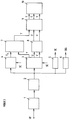
- FIG. 1 shows a PALplus receiver with an HF input HF, to which high-frequency PALplus signals transmitted via a conventional PAL transmission path are present, the basic composition of which is known from the literature references mentioned at the beginning.
- the signals are routed via a tuner 1 and an intermediate frequency circuit 2, which, apart from a broadband IF filter, are constructed in a conventional manner.
- a CVBS signal is available at the output of the intermediate frequency circuit 2.
- the signals U 'and V' provided at the output of the PAL decoder 20 are combined pixel by pixel in a multiplexer 21 to form a single-channel signal U '/ V'.
- the CVBS output signal of the intermediate frequency circuit 2 continues to be supplied to the luminance channel L of the television receiver. There, the successive fields A1, B1, A2, B2, etc. of the composite signal are fed to memory units 22 and 23, the odd fields A1, A2, A3 etc. of the memory unit 22 and the even fields B1, B2, B3, etc are assigned to the storage unit 23. Since - as will be explained in connection with FIG. 2 - a minimum delay is required between the start of the read-in process and the start of the read-out process, the memory 22 is a 4 Mbit memory and the memory 23 is a 2 Mbit memory .
- FIG. 2 shows a time diagram to explain the temporal relationships between the write-in and read-out processes from the memories 22 and 23 of FIG. 1.
- FIG. 2a shows the successive fields A1, B1, A2, B2, A3, ... of the CVBS signal.
- the odd-numbered fields A1, A2, A3, etc. are stored in the memory 22, which is dimensioned such that it can record the content of the active lines of two CVBS fields.
- the even-numbered fields B1, B2, B3, etc. are stored in the memory 23, which is dimensioned such that it can hold slightly more than the content of the active lines of a CVBS field.
- the hatched areas in Figure 2a correspond to the border line areas, i.e. the top and bottom 36 lines in each field.
- FIG. 2b shows the time intervals during which the odd fields A1, A2, etc. are read out of the memory 22 four times in succession at twice the reading frequency.
- FIG. 2c shows the time intervals during which the even fields B1, B2, etc. are also read out of the memory 23 four times in succession, likewise at double the readout frequency.
- a minimum delay t1 is provided between the start of reading in each odd field and the start of the first readout of the same field.
- the minimum delay mentioned ensures that the successive fields at the output of the respective memories can be made available at the same time, with the result that arithmetic 24 for Color-plus decoding - apart from a few line memories - no additional memory space is required.
- the parallel availability of successive fields is a prerequisite for the implementation of the Color Plus algorithm for separating the luminance and the chrominance components, which is based only on an addition of corresponding components from successive fields. Since the structure of this arithmetic is also not necessary for understanding the invention, it is not described in more detail here either. However, reference is made to the above-mentioned magazine plentiful- und Kino-Technik, 44 vol., No. 11/1990, pp. 595-602.
- the storage capacity of the memory 23 - as already stated above - must be somewhat larger (by at least 36 lines) than the storage capacity required to record a field, since otherwise the data of the field present in the time interval t2 of FIG. 2a B2 would undesirably partially overwrite the already stored data of field B1.
- the processing of the single-channel signal U '/ V' at the output of the multiplexer 21 is carried out in a manner similar to that of the FBAS signal in the luminance channel.
- the successive fields are supplied to memory units 27 and 28, the odd fields being assigned to the memory 27 and the even fields being assigned to the memory 28.
- the write-in and read-out time intervals correspond to those shown in FIG. 2.
- the memory capacity of the memories 27 and 28 is 2 Mbit and 1 Mbit.
- the output signals of the memories 27 and 28 are fed to the arithmetic 24 for color plus decoding and freed of luminance residues there.
- the crosstalk-free U / V signals present at the output of arithmetic 24 are subjected to a vertical upward conversion in a circuit 29 by means of interpolation and converted into parallel color difference signals U and V and, together with the likewise crosstalk-free luminance signal present at the output of arithmetic 25 for vertical upward interpolation Y fed to a 16: 9 screen 26.
- the signal can be displayed with a field frequency of 100 Hz either in the so-called AABB mode or in ABAB mode, depending on whether the image source material is a film scan or a camera recording.
- the multiplexer 21 and the write-in and read-out processes in or from the memories 22, 23, 27 and 28 are controlled by a microcomputer 30 which, among other things, evaluates the identification signals used in the transmitter from the CVBS output signal of the intermediate frequency circuit 2.
Landscapes
- Engineering & Computer Science (AREA)
- Multimedia (AREA)
- Signal Processing (AREA)
- Color Television Systems (AREA)
- Television Systems (AREA)
- Processing Of Color Television Signals (AREA)
Applications Claiming Priority (2)
| Application Number | Priority Date | Filing Date | Title |
|---|---|---|---|
| DE4243804A DE4243804C2 (de) | 1992-12-23 | 1992-12-23 | Empfänger zur Verarbeitung von nach dem Letterbox-Verfahren übertragenen Fernsehsignalen |
| DE4243804 | 1992-12-23 |
Publications (3)
| Publication Number | Publication Date |
|---|---|
| EP0607561A2 true EP0607561A2 (fr) | 1994-07-27 |
| EP0607561A3 EP0607561A3 (fr) | 1995-01-04 |
| EP0607561B1 EP0607561B1 (fr) | 2000-03-22 |
Family
ID=6476361
Family Applications (1)
| Application Number | Title | Priority Date | Filing Date |
|---|---|---|---|
| EP93119949A Expired - Lifetime EP0607561B1 (fr) | 1992-12-23 | 1993-12-10 | Récepteur pour traiter des signaux de télévision transmis selon la méthode letterbox |
Country Status (4)
| Country | Link |
|---|---|
| EP (1) | EP0607561B1 (fr) |
| AT (1) | ATE191115T1 (fr) |
| DE (2) | DE4243804C2 (fr) |
| ES (1) | ES2143999T3 (fr) |
Cited By (2)
| Publication number | Priority date | Publication date | Assignee | Title |
|---|---|---|---|---|
| EP0757481A3 (fr) * | 1995-08-02 | 1999-09-22 | Sony Corporation | Dispositif d'interpolation de trame, dispositif de traitement d'un signal vertical de renforcement, décodeur et récepteur de télévision |
| EP0763937A4 (fr) * | 1995-03-28 | 2000-02-23 | Sony Corp | Processeur de signaux d'image |
Families Citing this family (3)
| Publication number | Priority date | Publication date | Assignee | Title |
|---|---|---|---|---|
| DE4426382A1 (de) * | 1994-07-26 | 1996-02-01 | Thomson Brandt Gmbh | Decoder für PALplus-Signale mit einer zyklischen Schreib/Lese-Speichersteuerung |
| ATE194743T1 (de) * | 1994-11-23 | 2000-07-15 | Koninkl Philips Electronics Nv | Decodierung eines palplus-bildsignals |
| DE19640011A1 (de) * | 1996-09-27 | 1998-04-09 | Sony Deutschland Gmbh | Verfahren und Einrichtung zur Decodierung eines Fernsehsignals in einem Breitbild-Wiedergabemodus |
Family Cites Families (2)
| Publication number | Priority date | Publication date | Assignee | Title |
|---|---|---|---|---|
| GB2050109B (en) * | 1979-05-08 | 1984-01-25 | British Broadcasting Corp | Television display system |
| WO1992006565A1 (fr) * | 1990-10-01 | 1992-04-16 | Deutsche Thomson-Brandt Gmbh | Systeme de transmission de television et decodeur pour un systeme de transmission de television |
-
1992
- 1992-12-23 DE DE4243804A patent/DE4243804C2/de not_active Expired - Fee Related
-
1993
- 1993-12-10 EP EP93119949A patent/EP0607561B1/fr not_active Expired - Lifetime
- 1993-12-10 AT AT93119949T patent/ATE191115T1/de not_active IP Right Cessation
- 1993-12-10 DE DE59309985T patent/DE59309985D1/de not_active Expired - Lifetime
- 1993-12-10 ES ES93119949T patent/ES2143999T3/es not_active Expired - Lifetime
Cited By (2)
| Publication number | Priority date | Publication date | Assignee | Title |
|---|---|---|---|---|
| EP0763937A4 (fr) * | 1995-03-28 | 2000-02-23 | Sony Corp | Processeur de signaux d'image |
| EP0757481A3 (fr) * | 1995-08-02 | 1999-09-22 | Sony Corporation | Dispositif d'interpolation de trame, dispositif de traitement d'un signal vertical de renforcement, décodeur et récepteur de télévision |
Also Published As
| Publication number | Publication date |
|---|---|
| ATE191115T1 (de) | 2000-04-15 |
| DE4243804C2 (de) | 1995-08-17 |
| EP0607561B1 (fr) | 2000-03-22 |
| DE59309985D1 (de) | 2000-04-27 |
| EP0607561A3 (fr) | 1995-01-04 |
| DE4243804A1 (de) | 1994-07-07 |
| ES2143999T3 (es) | 2000-06-01 |
Similar Documents
| Publication | Publication Date | Title |
|---|---|---|
| DE3650665T2 (de) | Kompatibilität von Fernsehübertragungen mit vergrössertem und normalem Bildformat | |
| DE69416978T2 (de) | Videosignalverarbeitungsschaltung zur gleichzeitigen Darstellung von zwei Bildern | |
| DE3239362C2 (de) | System zur Erzeugung eines Bildes einer zeilenweise verschachtelt abgetasteten Szene | |
| DE69030408T2 (de) | Vorrichtung zur Umwandlung der Abtastzeilenanzahl für ein Videosignal und Abwärtsumwandler und Bild-in-Bild-Fernsehempfänger unter Anwendung derselben | |
| DE4012520A1 (de) | Fernsehsystem mit zoom-moeglichkeit fuer mindestens ein nebenbild | |
| DE69013744T2 (de) | Schaltung zur Verarbeitung eines Fernsehsignals. | |
| DE4219307A1 (de) | Breitwandfernsehempfaenger | |
| DE3442889C2 (de) | Verfahren zum Kodieren und Dekodieren eines Video-Signals sowie Schaltungsanordnung zu dessen Dekodierung | |
| DE69423500T2 (de) | Verfahren und Vorrichtung zur gleichzeitigen Darstellung von zwei Bildern | |
| DE3542102A1 (de) | Fernsehgeraet mit fortlaufender abtastung | |
| DE3916802A1 (de) | Fernsehgeraet | |
| EP0090211B1 (fr) | Appareil de reproduction sans scintillement d'images de télévision, de pages de textes et de pages de données graphiques | |
| DD290985A5 (de) | Mit herkoemmlichen normen kompatibles fernsehuebertragungssystem | |
| EP0318760A2 (fr) | Récepteur de télévision avec un dispositif de suppression des perturbations de scintillement | |
| DE69226994T2 (de) | Verarbeitungsvorrichtung für Videosignale zur Aliasinginterferenzminderung | |
| DE4243804C2 (de) | Empfänger zur Verarbeitung von nach dem Letterbox-Verfahren übertragenen Fernsehsignalen | |
| DE3348373C2 (fr) | ||
| EP0806877B1 (fr) | Procédé et dispositif pour le traitement d'un signal vidéo composite en couleurs avec une capacité de mémoire optimale | |
| DE3782814T2 (de) | Verbesserungen bezueglich des fernsehens. | |
| DE3941122C2 (fr) | ||
| DE3431261A1 (de) | Farbfernsehwiedergabegeraet | |
| DE3942204C1 (fr) | ||
| DE69700598T2 (de) | Gerät zum abtasten und anzeigen eines unterbildes mit einem hauptbild | |
| EP0424655B1 (fr) | Méthode de transmission de signaux vidéo d'une image à large écran pour la visualisation sur des récepteurs de télévision avec un format conventionnel ou agrandi | |
| DE69015676T2 (de) | Einrichtung zur Umwandlung der Bildfrequenz für einen HDTV-Fernsehempfänger und Verfahren zur Bewegungsdetektion in einem kodierten Fernsehbild. |
Legal Events
| Date | Code | Title | Description |
|---|---|---|---|
| PUAI | Public reference made under article 153(3) epc to a published international application that has entered the european phase |
Free format text: ORIGINAL CODE: 0009012 |
|
| AK | Designated contracting states |
Kind code of ref document: A2 Designated state(s): AT CH DE ES FR GB IT LI |
|
| PUAL | Search report despatched |
Free format text: ORIGINAL CODE: 0009013 |
|
| AK | Designated contracting states |
Kind code of ref document: A3 Designated state(s): AT CH DE ES FR GB IT LI |
|
| 17P | Request for examination filed |
Effective date: 19950306 |
|
| RAP1 | Party data changed (applicant data changed or rights of an application transferred) |
Owner name: GRUNDIG E.M.V. ELEKTRO-MECHANISCHE VERSUCHSANSTALT |
|
| RAP1 | Party data changed (applicant data changed or rights of an application transferred) |
Owner name: GRUNDIG AKTIENGESELLSCHAFT |
|
| GRAG | Despatch of communication of intention to grant |
Free format text: ORIGINAL CODE: EPIDOS AGRA |
|
| GRAG | Despatch of communication of intention to grant |
Free format text: ORIGINAL CODE: EPIDOS AGRA |
|
| GRAH | Despatch of communication of intention to grant a patent |
Free format text: ORIGINAL CODE: EPIDOS IGRA |
|
| 17Q | First examination report despatched |
Effective date: 19990415 |
|
| GRAH | Despatch of communication of intention to grant a patent |
Free format text: ORIGINAL CODE: EPIDOS IGRA |
|
| GRAA | (expected) grant |
Free format text: ORIGINAL CODE: 0009210 |
|
| AK | Designated contracting states |
Kind code of ref document: B1 Designated state(s): AT CH DE ES FR GB IT LI |
|
| REF | Corresponds to: |
Ref document number: 191115 Country of ref document: AT Date of ref document: 20000415 Kind code of ref document: T |
|
| REG | Reference to a national code |
Ref country code: CH Ref legal event code: NV Representative=s name: BOVARD AG PATENTANWAELTE Ref country code: CH Ref legal event code: EP |
|
| GBT | Gb: translation of ep patent filed (gb section 77(6)(a)/1977) |
Effective date: 20000324 |
|
| REF | Corresponds to: |
Ref document number: 59309985 Country of ref document: DE Date of ref document: 20000427 |
|
| ET | Fr: translation filed | ||
| REG | Reference to a national code |
Ref country code: ES Ref legal event code: FG2A Ref document number: 2143999 Country of ref document: ES Kind code of ref document: T3 |
|
| ITF | It: translation for a ep patent filed | ||
| RAP2 | Party data changed (patent owner data changed or rights of a patent transferred) |
Owner name: GRUNDIG AKTIENGESELLSCHAFT |
|
| REG | Reference to a national code |
Ref country code: GB Ref legal event code: 746 Effective date: 20001130 |
|
| PLBE | No opposition filed within time limit |
Free format text: ORIGINAL CODE: 0009261 |
|
| STAA | Information on the status of an ep patent application or granted ep patent |
Free format text: STATUS: NO OPPOSITION FILED WITHIN TIME LIMIT |
|
| 26N | No opposition filed | ||
| REG | Reference to a national code |
Ref country code: FR Ref legal event code: D6 |
|
| REG | Reference to a national code |
Ref country code: GB Ref legal event code: IF02 |
|
| REG | Reference to a national code |
Ref country code: CH Ref legal event code: PUE Owner name: GRUNDIG MULTIMEDIA B.V. Free format text: GRUNDIG AKTIENGESELLSCHAFT#KURGARTENSTRASSE 37#90762 FUERTH (DE) -TRANSFER TO- GRUNDIG MULTIMEDIA B.V.#DE BOELELAAN 7 OFF. I 2 HG#1083HJ AMSTERDAM (NL) |
|
| REG | Reference to a national code |
Ref country code: GB Ref legal event code: 732E |
|
| REG | Reference to a national code |
Ref country code: FR Ref legal event code: TP |
|
| PGFP | Annual fee paid to national office [announced via postgrant information from national office to epo] |
Ref country code: ES Payment date: 20091209 Year of fee payment: 17 Ref country code: CH Payment date: 20091224 Year of fee payment: 17 Ref country code: AT Payment date: 20091222 Year of fee payment: 17 |
|
| PGFP | Annual fee paid to national office [announced via postgrant information from national office to epo] |
Ref country code: IT Payment date: 20091217 Year of fee payment: 17 Ref country code: GB Payment date: 20091231 Year of fee payment: 17 Ref country code: FR Payment date: 20100106 Year of fee payment: 17 |
|
| PGFP | Annual fee paid to national office [announced via postgrant information from national office to epo] |
Ref country code: DE Payment date: 20091229 Year of fee payment: 17 |
|
| REG | Reference to a national code |
Ref country code: CH Ref legal event code: PFA Owner name: GRUNDIG MULTIMEDIA B.V. Free format text: GRUNDIG MULTIMEDIA B.V.#DE BOELELAAN 7 OFF. I 2 HG#1083HJ AMSTERDAM (NL) -TRANSFER TO- GRUNDIG MULTIMEDIA B.V.#DE BOELELAAN 7 OFF. I 2 HG#1083HJ AMSTERDAM (NL) |
|
| REG | Reference to a national code |
Ref country code: CH Ref legal event code: PL |
|
| GBPC | Gb: european patent ceased through non-payment of renewal fee |
Effective date: 20101210 |
|
| PG25 | Lapsed in a contracting state [announced via postgrant information from national office to epo] |
Ref country code: AT Free format text: LAPSE BECAUSE OF NON-PAYMENT OF DUE FEES Effective date: 20101210 |
|
| REG | Reference to a national code |
Ref country code: FR Ref legal event code: ST Effective date: 20110831 |
|
| PG25 | Lapsed in a contracting state [announced via postgrant information from national office to epo] |
Ref country code: CH Free format text: LAPSE BECAUSE OF NON-PAYMENT OF DUE FEES Effective date: 20101231 Ref country code: LI Free format text: LAPSE BECAUSE OF NON-PAYMENT OF DUE FEES Effective date: 20101231 Ref country code: FR Free format text: LAPSE BECAUSE OF NON-PAYMENT OF DUE FEES Effective date: 20110103 |
|
| REG | Reference to a national code |
Ref country code: DE Ref legal event code: R119 Ref document number: 59309985 Country of ref document: DE Effective date: 20110701 |
|
| PG25 | Lapsed in a contracting state [announced via postgrant information from national office to epo] |
Ref country code: DE Free format text: LAPSE BECAUSE OF NON-PAYMENT OF DUE FEES Effective date: 20110701 Ref country code: GB Free format text: LAPSE BECAUSE OF NON-PAYMENT OF DUE FEES Effective date: 20101210 |
|
| PG25 | Lapsed in a contracting state [announced via postgrant information from national office to epo] |
Ref country code: IT Free format text: LAPSE BECAUSE OF NON-PAYMENT OF DUE FEES Effective date: 20101210 |
|
| REG | Reference to a national code |
Ref country code: ES Ref legal event code: FD2A Effective date: 20120206 |
|
| PG25 | Lapsed in a contracting state [announced via postgrant information from national office to epo] |
Ref country code: ES Free format text: LAPSE BECAUSE OF NON-PAYMENT OF DUE FEES Effective date: 20101211 |