EP0607603A1 - Machine de travail avec au moins deux groupes d'outils de travail - Google Patents
Machine de travail avec au moins deux groupes d'outils de travail Download PDFInfo
- Publication number
- EP0607603A1 EP0607603A1 EP93120791A EP93120791A EP0607603A1 EP 0607603 A1 EP0607603 A1 EP 0607603A1 EP 93120791 A EP93120791 A EP 93120791A EP 93120791 A EP93120791 A EP 93120791A EP 0607603 A1 EP0607603 A1 EP 0607603A1
- Authority
- EP
- European Patent Office
- Prior art keywords
- valve
- switch
- tool according
- working
- tools
- Prior art date
- Legal status (The legal status is an assumption and is not a legal conclusion. Google has not performed a legal analysis and makes no representation as to the accuracy of the status listed.)
- Granted
Links
- 230000000903 blocking effect Effects 0.000 claims description 3
- 238000009331 sowing Methods 0.000 description 9
- 239000002689 soil Substances 0.000 description 7
- 239000003337 fertilizer Substances 0.000 description 4
- 239000012530 fluid Substances 0.000 description 4
- 239000007788 liquid Substances 0.000 description 2
- 238000000034 method Methods 0.000 description 2
- 230000004913 activation Effects 0.000 description 1
- 238000009412 basement excavation Methods 0.000 description 1
- 230000008878 coupling Effects 0.000 description 1
- 238000010168 coupling process Methods 0.000 description 1
- 238000005859 coupling reaction Methods 0.000 description 1
- 230000001419 dependent effect Effects 0.000 description 1
- 238000000151 deposition Methods 0.000 description 1
- 239000000463 material Substances 0.000 description 1
- 238000010899 nucleation Methods 0.000 description 1
- 230000035515 penetration Effects 0.000 description 1
- 238000010079 rubber tapping Methods 0.000 description 1
- 239000000126 substance Substances 0.000 description 1
- 238000003971 tillage Methods 0.000 description 1
Images

Classifications
-
- A—HUMAN NECESSITIES
- A01—AGRICULTURE; FORESTRY; ANIMAL HUSBANDRY; HUNTING; TRAPPING; FISHING
- A01B—SOIL WORKING IN AGRICULTURE OR FORESTRY; PARTS, DETAILS, OR ACCESSORIES OF AGRICULTURAL MACHINES OR IMPLEMENTS, IN GENERAL
- A01B63/00—Lifting or adjusting devices or arrangements for agricultural machines or implements
- A01B63/14—Lifting or adjusting devices or arrangements for agricultural machines or implements for implements drawn by animals or tractors
- A01B63/24—Tools or tool-holders adjustable relatively to the frame
- A01B63/32—Tools or tool-holders adjustable relatively to the frame operated by hydraulic or pneumatic means without automatic control
-
- A—HUMAN NECESSITIES
- A01—AGRICULTURE; FORESTRY; ANIMAL HUSBANDRY; HUNTING; TRAPPING; FISHING
- A01C—PLANTING; SOWING; FERTILISING
- A01C7/00—Sowing
- A01C7/08—Broadcast seeders; Seeders depositing seeds in rows
- A01C7/088—Sectional seeding
-
- A—HUMAN NECESSITIES
- A01—AGRICULTURE; FORESTRY; ANIMAL HUSBANDRY; HUNTING; TRAPPING; FISHING
- A01C—PLANTING; SOWING; FERTILISING
- A01C7/00—Sowing
- A01C7/20—Parts of seeders for conducting and depositing seed
- A01C7/201—Mounting of the seeding tools
- A01C7/205—Mounting of the seeding tools comprising pressure regulation means
-
- Y—GENERAL TAGGING OF NEW TECHNOLOGICAL DEVELOPMENTS; GENERAL TAGGING OF CROSS-SECTIONAL TECHNOLOGIES SPANNING OVER SEVERAL SECTIONS OF THE IPC; TECHNICAL SUBJECTS COVERED BY FORMER USPC CROSS-REFERENCE ART COLLECTIONS [XRACs] AND DIGESTS
- Y10—TECHNICAL SUBJECTS COVERED BY FORMER USPC
- Y10S—TECHNICAL SUBJECTS COVERED BY FORMER USPC CROSS-REFERENCE ART COLLECTIONS [XRACs] AND DIGESTS
- Y10S111/00—Planting
- Y10S111/922—Variable drive mechanism
Definitions
- the invention relates to a working device with at least two sets of working tools and at least one lifting cylinder associated with each set of working tools, which can be pressurized depending on the position of a control device such that the working tools can be adjusted jointly between a lowered and a raised position.
- Such tools are used particularly in agriculture, and their tools can work the soil or spread seeds or fertilizers in a field.
- Soil cultivation equipment, crop protection equipment, fertilizer spreaders or seeders can be named as examples, wherein in the case of the seed drills, the work tools include furrow openers which penetrate the soil in the working position.
- the working width of such implements, which are usually pulled across the field by an agricultural tractor, is increasing. It can be up to 10m and more.
- various driving methods are conceivable. The tractor driver can start with the first lane at the edge of the field, turn at the end of the field and lay the second lane next to the first lane when driving in the opposite direction.
- the work tools divided into groups are raised together by lifting cylinders connected in parallel with one another, with additional hydraulic pressure being exerted on the work tools in the ground position can, so that the working tools designed as furrow openers penetrate the soil equally deep and deposit the seed at the same soil depth. In the transport position, seed leakage is automatically interrupted.
- the object to be achieved with the invention is seen in providing this excavation mechanism, which goes back to the applicant, in a simple and inexpensive manner with a device which prevents double processing.
- the invention therefore also provides a valve assigned to at least one lifting cylinder and adjustable between two positions, which in its first position allows a common adjustment of the work tools and in the second position a separate adjustment of the work tools.
- the invention works in the first position of the valve, like the working device considered in the genre, while in the second position of the valve it is possible to control at least one group of working tools.
- each lifting cylinder can be acted on on both sides, which, when loaded, adjusts the associated sets of working tools between a lower working position in the field and a raised transport position, which is why the invention further provides for individual or optional control of all groups that each lifting cylinder has a separate valve is assigned, each valve being remotely controllable, so that a high control from the field position into the transport position and vice versa can take place from a pulling vehicle.
- each valve be designed as an electromagnetic reversing valve or as a check valve.
- this is designed as a four-way / two-position valve, the lifting cylinders being connected in parallel with one another.
- the control device can be designed as a control valve adjustable between a first and a second position, which in its first position permits pressurizing the cylinder-side ends of the lifting cylinders and in its second position pressurizing the piston rod ends of the lifting cylinders, which is why after Invention for such a case can also be provided that each reversing valve in its first position leaves the pressure medium acting on the lifting cylinders unchanged by the control valve and in its second position reverses the pressure medium acting on the lifting cylinders. This means that the position of the control device does not have to be changed for high control from the field position. If the reversing valve is returned to its second position, the highly controlled group automatically returns to its specified field position.
- each reversing valve is provided with a solenoid, and each solenoid can be connected to an electrical power source via a switch, the switch being open in the first position of the reversing valve and closed in the second position of the reversing valve.
- the inputs of the switches are wired to their outputs and that a main stroke switch is provided in this connection. With such wiring, the control device can also remain in its position in which the work tools normally assume their field position.
- diodes can also be provided between the main stroke switch and the outputs of the switches.
- the invention provides that the inputs of the switches with the output of a normally open relay switch of a first relay are connected, the coil of which is connected to the first output terminal of a button and to the input of a normally closed relay switch of a second relay, the coil of which is connected to a second output terminal of the button and, like the output of the normally closed relay switch, is grounded, the input of the normally open relay switch and the input of the button are connected to the electrical power source and the output of the normally open relay switch to the input of its coil.
- the button is designed as a single-pole main changeover switch, which returns to its zero position after tapping, since a holding loop forms at the first relay, which keeps the coil of this relay energized.
- the first output of the button can also be connected to the inputs of the switches.
- each check valve in its first position leaves the pressure medium acting on the lifting cylinders unchanged by the control valve, and in its second position it blocks one of the two lines leading to each lifting cylinder.
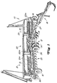
- an implement which can be used in agriculture is designated 10 and can be designed as a seed drill.
- Such devices usually have a relatively large working width, which can be reduced for transport trips but does not have to.
- the device 10 has a base frame 12 and is supported in use on wheels 14 and 16. Via a drawbar 18, the device 10 can be attached to a pulling vehicle, such as an agricultural tractor not shown in the drawing.
- the device 10 is designed as a multi-group device and, in the preferred exemplary embodiment, has three groups 21, 22 and 23 with sets 25, 26 and 27 of conventional tools 30 which penetrate into the soil, such as furrow openers for depositing the seed into the soil.
- the depth of penetration is adjustable, and each group or set 25, 26 and 27 can be adjusted between a lower working position and a higher transport position via cylinders 31, 32 and 33 which can be acted upon from both sides.
- Each set of tools 25, 26, 27 is assigned a crankshaft, not shown in the drawing, which can be pivoted about a transverse axis with respect to the base frame 12 for adjusting the work tools via the cylinders 31, 32, 33.
- the cylinders 31, 32 and 33 are connected to a pressure source for hydraulic fluid provided on the towing vehicle and can be controlled via a conventional control valve 40.
- a pressure regulator 42 is also provided between the control valve 40 and the cylinders 31, 32 and 33. From Fig. 2 it can still be seen that the cylinders 31, 32, 33 are normally connected to one another via a line 44 which is connected to the cylinder-side ends of the cylinders and via a line 46 which is connected to the piston rod-side ends of the cylinders are connected in parallel.
- the crankshafts are pivoted in a direction of rotation, which causes the tools 30 to be lifted or lifted out.
- Pressurization of the cylinder-side ends of the cylinders results in the working tools 30 being lowered into their working position and at the same time in maintaining a preselectable downward pressure on the working tools 30 depending on the setting of the pressure regulator 42.
- the pressure at the cylinder end of the cylinder and thus the pressure acting on the tools in the working position is thus determined by the setting of the pressure regulator.
- the present invention is based on such a system, but can be used wherever there is a need to avoid double processing. Because, depending on the driving style or working method of a field or field, it can happen, especially with very wide implements, that the implement has to run over strips that have already been worked on, but not in their entire width. Duplication is associated with increased financial expenditure, can lead to reworking or can put excessive strain on the floor. Examples would be a double application of seed or seedlings or chemicals. Double tillage would also be of little help. According to the preferred embodiment, the individual sets of work tools can therefore be individually controlled, in which case, in the case of a spreading device (fertilizer, planting or sowing machine, for example), the spreading of the material is still interrupted.
- a spreading device fertilizer, planting or sowing machine, for example
- the individual device groups have a conventional quantity control system (21m-23m in FIG. 1) with seed dosers and a drive shaft, the drive of which is automatically switched off via a coupling (not shown) as soon as the tools 30 approach the transport position.
- the seed metering devices are driven again or the clutch is automatically engaged again when the tools 30 approach their working position or are in this again.
- a section control 50 is provided for controlling the individual tool sets and is shown in detail in FIG. 2. It has reversing valves 51, 52 and 53 which are provided between the lines 44 and 46 and via which, in a first embodiment, the line 44 with the ends of the cylinders 31 to 33 on the piston rod side and the line 46 with the can connect cylinder-side ends of the cylinders 31 to 33.
- the reversing valves 51 to 53 are designed as four-way / two-position valves and are each provided with a solenoid 51a, 52a and 53a. If the solenoids are not activated, then the reversing valves 51 to 53 assume the position shown in FIG.
- the tools 30 are conventionally raised and lowered, together over the entire width of the device.
- the adjustable ground pressure acting on all tools can be generated in the working position, as described in the already mentioned document US-A-5 065 681.
- Each solenoid 51a, 52a, 53a is wired to one side of a switch 61, 62, 63 which is provided on a switch panel 64 or switch box at the driver's station of the pulling vehicle and the other side of which is connected to an energy source 65 on the vehicle via a locking relay 66 having a solenoid 66a and a relay switch 66b.
- Another relay 67 with a solenoid 67a and a normally closed relay switch 67b is still provided between the solenoid 66a and the ground.
- a single pole master switch 68 is provided between relays 66 and 67 and power source 65.
- This changeover switch 68 is designed as a toggle switch that can be switched on for a short time and has a lower output connected to the switches 61 to 63 and to the relay solenoid 66a for an employment and an upper output connected to the solenoid 67a for an exhibition.
- the toggle switch When the toggle switch is tilted to its lower position, the solenoid 66a is activated and the relay switch 66b is closed. This creates a holding loop which keeps the relay switch 66b closed so that the inputs of the switches 61, 62 and 63 can be supplied with energy. If the toggle switch 68 is then tilted into its position, the normally closed relay switch 67b opens and the connection of the solenoid 66a to the ground is interrupted.
- the relay switch 66b opens and the energy supply to the switches 61 to 63 is interrupted.
- the changeover switch 68 In order to be able to apply the switches 61 to 63 again to voltage, the changeover switch 68 must be in its position again be briefly tilted so that a holding circuit for the relay switch 66b can be created again.
- An indicator lamp 69 is also provided between the output of the relay 66 and the ground so that an operator can recognize that the switch box 64 is activated.
- a main stroke switch 70 is connected to the output of the relay 66 and to the solenoids 51a, 52a and 53a, block diodes 71, 72 and 73 being provided in this connection.
- a diode 80 is also connected to the diodes 71 to 73 in order to limit negative voltage peaks when any switch is opened.
- switch 70 When switch 70 is closed, all solenoids 51a, 52a and 53a are activated and the flow of liquid to the cylinders is reversed, whereby the pistons are inserted into the associated cylinders and the tools are lifted, regardless of the position of switches 61, 62 and 63 With this, an operator can, with the switch box 64 switched on, use the switch 70 without actuating the control valve 40 or without adjusting one of the switches 61 to 63 to lift out all the tools, which occurs, for example, at the end of a field and when turning. As soon as the switch 70 is then opened again, the pistons of the cylinders return to their previous positions, which are dependent on the respective switching positions of the switches 61, 62 and 63.
- solenoid 51a For example, if the operator wants to prevent double sowing on the right side of the machine, he switches switch 61 into its closed position when switch box 64 is switched on, whereupon solenoid 51a is activated. This in turn causes the spool of the reversing valve 51 to be moved from its position shown in FIG. 2 to the right so that the piston of the cylinder 31 is retracted, the tool set 25 of the device group 21 is lifted out of the ground and the seed supply to this set is interrupted . To return to sowing across the entire machine width, the solenoid 51a is deactivated by opening the switch. The reversing valve 51 returns to its position shown in Fig. 2 and the tools are returned to the ground.
- the solenoid 53a is activated and the tools on the group 23 are lifted out.
- two solenoids 51a, 52a, 53a are activated in order to be able to dig out the associated two sets of tools 25 to 27, with only a single set remaining ready for use. Any combination of tool sets can be excavated to avoid double seeding.
- Fig. 4 shows an embodiment in which, while leaving the main lift switch 70, the reversing valves 51 to 53 have been replaced by blocking valves 51b, which selectively block a pressure medium supply to the cylinder-side end of the cylinder when the solenoid is activated or when the switch 61 to 63 is switched on. If all the tools are in their working position, the operator must activate the valve 51b or block the pressure medium supply to the cylinder-side end of the cylinder whose associated tool group is to continue sowing. The work tools of the other group or groups are lifted hydraulically in a conventional manner and the seed supply is stopped, with only the selected group remaining ready for operation in its working position. In order to then be able to sow again over the entire machine width, the excavated groups are lowered again and the valve 51b is deactivated for a normal fluid flow to the corresponding cylinder.
Landscapes
- Life Sciences & Earth Sciences (AREA)
- Soil Sciences (AREA)
- Environmental Sciences (AREA)
- Zoology (AREA)
- Engineering & Computer Science (AREA)
- Mechanical Engineering (AREA)
- Lifting Devices For Agricultural Implements (AREA)
Applications Claiming Priority (2)
| Application Number | Priority Date | Filing Date | Title |
|---|---|---|---|
| US08/007,863 US5358055A (en) | 1993-01-22 | 1993-01-22 | Partial width seeding attachment |
| US7863 | 1993-01-22 |
Publications (2)
| Publication Number | Publication Date |
|---|---|
| EP0607603A1 true EP0607603A1 (fr) | 1994-07-27 |
| EP0607603B1 EP0607603B1 (fr) | 1996-09-04 |
Family
ID=21728501
Family Applications (1)
| Application Number | Title | Priority Date | Filing Date |
|---|---|---|---|
| EP93120791A Expired - Lifetime EP0607603B1 (fr) | 1993-01-22 | 1993-12-23 | Machine de travail avec au moins deux groupes d'outils de travail |
Country Status (5)
| Country | Link |
|---|---|
| US (1) | US5358055A (fr) |
| EP (1) | EP0607603B1 (fr) |
| CA (1) | CA2109290C (fr) |
| DE (1) | DE59303653D1 (fr) |
| MX (1) | MX9307798A (fr) |
Families Citing this family (7)
| Publication number | Priority date | Publication date | Assignee | Title |
|---|---|---|---|---|
| US5449042A (en) * | 1994-05-04 | 1995-09-12 | Deere & Company | Rephasing controlling/controlled hydraulic cylinders in folding implement frame |
| US8408326B2 (en) * | 2010-05-28 | 2013-04-02 | Cnh Canada, Ltd. | Hydraulic remote control for hydraulic system of an agricultural implement |
| US8176992B2 (en) | 2010-05-28 | 2012-05-15 | Cnh Canada, Ltd. | Electronically controlled hydraulic system for an agricultural implement |
| WO2013112929A2 (fr) | 2012-01-25 | 2013-08-01 | Precision Planting Llc | Appareil de barre porte-outils agricole, systèmes et procédés associés |
| RU2600182C2 (ru) * | 2012-06-28 | 2016-10-20 | Кинз Мэньюфэкчеринг, Инк. | Система распределения массы для семенных сеялок и машин для внесения продуктов |
| US9000314B2 (en) | 2012-11-21 | 2015-04-07 | Caterpillar Inc. | Switch assembly having unintentional-actuation guard |
| US9265188B2 (en) * | 2012-12-07 | 2016-02-23 | Cnh Industrial Canada, Ltd. | Sectioned meter box assembly |
Citations (3)
| Publication number | Priority date | Publication date | Assignee | Title |
|---|---|---|---|---|
| FR2137926A1 (fr) * | 1971-05-17 | 1972-12-29 | Deere & Co | |
| US4413685A (en) * | 1979-12-11 | 1983-11-08 | Gremelspacher Philip E | Planter implement with adjusting position-display apparatus and system thereof |
| US5065681A (en) * | 1990-10-10 | 1991-11-19 | Deere & Company | Hydraulic down pressure structure for an implement with multiple ground engaging tools |
Family Cites Families (7)
| Publication number | Priority date | Publication date | Assignee | Title |
|---|---|---|---|---|
| US2587750A (en) * | 1948-11-05 | 1952-03-04 | Morrison Montford | Vacuum tube oscillator system |
| US3627059A (en) * | 1969-12-22 | 1971-12-14 | Deere & Co | Gauge wheel assembly for agricultural implements |
| US3910326A (en) * | 1974-10-29 | 1975-10-07 | Case Co J I | Tree harvesting apparatus with accumulator mechanism |
| US4339139A (en) * | 1980-06-05 | 1982-07-13 | International Harvester Co. | Hydraulic circuit for synchronous lift of flexible frame implements |
| JPS57197334A (en) * | 1981-05-26 | 1982-12-03 | Komatsu Ltd | Electric oil pressure controller for construction vehicle |
| US4487106A (en) * | 1983-11-04 | 1984-12-11 | Towmotor Corporation | Fluid operated system |
| JPS622805U (fr) * | 1985-06-20 | 1987-01-09 |
-
1993
- 1993-01-22 US US08/007,863 patent/US5358055A/en not_active Expired - Lifetime
- 1993-10-26 CA CA002109290A patent/CA2109290C/fr not_active Expired - Fee Related
- 1993-12-09 MX MX9307798A patent/MX9307798A/es not_active IP Right Cessation
- 1993-12-23 DE DE59303653T patent/DE59303653D1/de not_active Expired - Lifetime
- 1993-12-23 EP EP93120791A patent/EP0607603B1/fr not_active Expired - Lifetime
Patent Citations (3)
| Publication number | Priority date | Publication date | Assignee | Title |
|---|---|---|---|---|
| FR2137926A1 (fr) * | 1971-05-17 | 1972-12-29 | Deere & Co | |
| US4413685A (en) * | 1979-12-11 | 1983-11-08 | Gremelspacher Philip E | Planter implement with adjusting position-display apparatus and system thereof |
| US5065681A (en) * | 1990-10-10 | 1991-11-19 | Deere & Company | Hydraulic down pressure structure for an implement with multiple ground engaging tools |
Also Published As
| Publication number | Publication date |
|---|---|
| DE59303653D1 (de) | 1996-10-10 |
| CA2109290C (fr) | 1996-03-19 |
| CA2109290A1 (fr) | 1994-07-23 |
| EP0607603B1 (fr) | 1996-09-04 |
| US5358055A (en) | 1994-10-25 |
| MX9307798A (es) | 1994-07-29 |
Similar Documents
| Publication | Publication Date | Title |
|---|---|---|
| DE69602816T2 (de) | Ziehbares landwirtschaftliches gerät | |
| DE69703512T2 (de) | Regelung für einen halbgetragenen Pflug | |
| EP2982230A1 (fr) | Semoir | |
| EP0607603B1 (fr) | Machine de travail avec au moins deux groupes d'outils de travail | |
| EP0201046A2 (fr) | Outil de travail, en particulier outil de travail du sol | |
| DE10038595A1 (de) | Steuervorrichtung einer Koppelstange | |
| DE2940615A1 (de) | Vorrichtung zur durchfuehrung des spurschachtverfahrens bei der aussat von saatgut und/oder duengemitteln | |
| DE3438353C2 (fr) | ||
| DE3440625A1 (de) | Landwirtschaftlicher schlepper | |
| EP4104654B1 (fr) | Appareil de traitement du sol à protection hydraulique contre les surcharges | |
| DE10107139B4 (de) | Pflug | |
| DE19611626A1 (de) | Hydraulische Schleppersteuerung | |
| DE202021104824U1 (de) | Landwirtschaftliche Arbeitsmaschine | |
| DE69419341T2 (de) | Bodenbearbeitungsmaschine | |
| EP4275465B1 (fr) | Dispositif de réglage hydraulique | |
| DE69823588T2 (de) | Steuereinrichtung für einen Pflug | |
| DE3240278A1 (de) | Einrichtung zum regeln eines an einem landwirtschaftlichen schlepper angebauten arbeitsgeraetes | |
| DE1141826B (de) | Vorrichtung zum Umschalten des Krafthebers eines Ackerschleppers auf automatische Steuerung oder gleichbleibende Lage des Ackergeraetes | |
| DE2206364A1 (de) | Umschaltvorrichtung für Markierungsvorrichtungen an landwirtschaftlichen Maschinen zum Säen oder Pflanzen | |
| DE3143538C2 (de) | Einrichtung zum Regeln der Arbeitstiefe eines an einem landwirtschaftlichen Schlepper angebauten Arbeitsgerätes | |
| DE3406228C2 (fr) | ||
| DE908426C (de) | Selbstfahrendes Ackergeraet mit heb- und senkbarem Werkzeugtraeger und einer mit letzterem verbundenen zuglastempfindlichen Hubvorrichtung | |
| DE69108834T2 (de) | Hydraulisches Steuersystem für Werkzeuggruppen. | |
| EP3892078B1 (fr) | Machine de travail agricole et procédé d'opération d'une machine de travail agricole | |
| AT380376B (de) | Steuerung fuer hydraulische oder pneumatische bodenbearbeitungsgeraete |
Legal Events
| Date | Code | Title | Description |
|---|---|---|---|
| PUAI | Public reference made under article 153(3) epc to a published international application that has entered the european phase |
Free format text: ORIGINAL CODE: 0009012 |
|
| 17P | Request for examination filed |
Effective date: 19940513 |
|
| AK | Designated contracting states |
Kind code of ref document: A1 Designated state(s): DE FR IT SE |
|
| 17Q | First examination report despatched |
Effective date: 19951016 |
|
| GRAG | Despatch of communication of intention to grant |
Free format text: ORIGINAL CODE: EPIDOS AGRA |
|
| GRAH | Despatch of communication of intention to grant a patent |
Free format text: ORIGINAL CODE: EPIDOS IGRA |
|
| GRAH | Despatch of communication of intention to grant a patent |
Free format text: ORIGINAL CODE: EPIDOS IGRA |
|
| GRAA | (expected) grant |
Free format text: ORIGINAL CODE: 0009210 |
|
| AK | Designated contracting states |
Kind code of ref document: B1 Designated state(s): DE FR IT SE |
|
| REF | Corresponds to: |
Ref document number: 59303653 Country of ref document: DE Date of ref document: 19961010 |
|
| ET | Fr: translation filed | ||
| ITF | It: translation for a ep patent filed | ||
| PLBQ | Unpublished change to opponent data |
Free format text: ORIGINAL CODE: EPIDOS OPPO |
|
| PLBI | Opposition filed |
Free format text: ORIGINAL CODE: 0009260 |
|
| PLBF | Reply of patent proprietor to notice(s) of opposition |
Free format text: ORIGINAL CODE: EPIDOS OBSO |
|
| 26 | Opposition filed |
Opponent name: MAASLAND N.V. Effective date: 19970528 |
|
| PLBF | Reply of patent proprietor to notice(s) of opposition |
Free format text: ORIGINAL CODE: EPIDOS OBSO |
|
| PLBO | Opposition rejected |
Free format text: ORIGINAL CODE: EPIDOS REJO |
|
| PLBN | Opposition rejected |
Free format text: ORIGINAL CODE: 0009273 |
|
| STAA | Information on the status of an ep patent application or granted ep patent |
Free format text: STATUS: OPPOSITION REJECTED |
|
| 27O | Opposition rejected |
Effective date: 19980808 |
|
| PGFP | Annual fee paid to national office [announced via postgrant information from national office to epo] |
Ref country code: SE Payment date: 20041221 Year of fee payment: 12 |
|
| PG25 | Lapsed in a contracting state [announced via postgrant information from national office to epo] |
Ref country code: IT Free format text: LAPSE BECAUSE OF NON-PAYMENT OF DUE FEES;WARNING: LAPSES OF ITALIAN PATENTS WITH EFFECTIVE DATE BEFORE 2007 MAY HAVE OCCURRED AT ANY TIME BEFORE 2007. THE CORRECT EFFECTIVE DATE MAY BE DIFFERENT FROM THE ONE RECORDED. Effective date: 20051223 |
|
| PG25 | Lapsed in a contracting state [announced via postgrant information from national office to epo] |
Ref country code: SE Free format text: LAPSE BECAUSE OF NON-PAYMENT OF DUE FEES Effective date: 20051224 |
|
| EUG | Se: european patent has lapsed | ||
| PGFP | Annual fee paid to national office [announced via postgrant information from national office to epo] |
Ref country code: FR Payment date: 20120104 Year of fee payment: 19 |
|
| PGFP | Annual fee paid to national office [announced via postgrant information from national office to epo] |
Ref country code: DE Payment date: 20121231 Year of fee payment: 20 |
|
| REG | Reference to a national code |
Ref country code: FR Ref legal event code: ST Effective date: 20130830 |
|
| PG25 | Lapsed in a contracting state [announced via postgrant information from national office to epo] |
Ref country code: FR Free format text: LAPSE BECAUSE OF NON-PAYMENT OF DUE FEES Effective date: 20130102 |
|
| REG | Reference to a national code |
Ref country code: DE Ref legal event code: R071 Ref document number: 59303653 Country of ref document: DE |
|
| PG25 | Lapsed in a contracting state [announced via postgrant information from national office to epo] |
Ref country code: DE Free format text: LAPSE BECAUSE OF EXPIRATION OF PROTECTION Effective date: 20131224 |