EP0607604A1 - Hydraulisches System für ein Fahrzeug - Google Patents
Hydraulisches System für ein Fahrzeug Download PDFInfo
- Publication number
- EP0607604A1 EP0607604A1 EP93120792A EP93120792A EP0607604A1 EP 0607604 A1 EP0607604 A1 EP 0607604A1 EP 93120792 A EP93120792 A EP 93120792A EP 93120792 A EP93120792 A EP 93120792A EP 0607604 A1 EP0607604 A1 EP 0607604A1
- Authority
- EP
- European Patent Office
- Prior art keywords
- pump
- vehicle
- hydraulic system
- liquid
- line
- Prior art date
- Legal status (The legal status is an assumption and is not a legal conclusion. Google has not performed a legal analysis and makes no representation as to the accuracy of the status listed.)
- Granted
Links
- 230000002706 hydrostatic effect Effects 0.000 claims description 12
- 239000003380 propellant Substances 0.000 claims description 10
- 238000002485 combustion reaction Methods 0.000 claims description 3
- 239000007788 liquid Substances 0.000 description 44
- 238000001816 cooling Methods 0.000 description 5
- 239000012530 fluid Substances 0.000 description 3
- 238000010438 heat treatment Methods 0.000 description 2
- 230000005540 biological transmission Effects 0.000 description 1
- 230000015572 biosynthetic process Effects 0.000 description 1
- 238000009833 condensation Methods 0.000 description 1
- 230000005494 condensation Effects 0.000 description 1
- 230000006378 damage Effects 0.000 description 1
- 238000010586 diagram Methods 0.000 description 1
- 230000029142 excretion Effects 0.000 description 1
- 238000012423 maintenance Methods 0.000 description 1
- 238000004519 manufacturing process Methods 0.000 description 1
- 238000013021 overheating Methods 0.000 description 1
- 230000005855 radiation Effects 0.000 description 1
- 239000007787 solid Substances 0.000 description 1
Images

Classifications
-
- F—MECHANICAL ENGINEERING; LIGHTING; HEATING; WEAPONS; BLASTING
- F15—FLUID-PRESSURE ACTUATORS; HYDRAULICS OR PNEUMATICS IN GENERAL
- F15B—SYSTEMS ACTING BY MEANS OF FLUIDS IN GENERAL; FLUID-PRESSURE ACTUATORS, e.g. SERVOMOTORS; DETAILS OF FLUID-PRESSURE SYSTEMS, NOT OTHERWISE PROVIDED FOR
- F15B11/00—Servomotor systems without provision for follow-up action; Circuits therefor
- F15B11/16—Servomotor systems without provision for follow-up action; Circuits therefor with two or more servomotors
- F15B11/17—Servomotor systems without provision for follow-up action; Circuits therefor with two or more servomotors using two or more pumps
-
- F—MECHANICAL ENGINEERING; LIGHTING; HEATING; WEAPONS; BLASTING
- F15—FLUID-PRESSURE ACTUATORS; HYDRAULICS OR PNEUMATICS IN GENERAL
- F15B—SYSTEMS ACTING BY MEANS OF FLUIDS IN GENERAL; FLUID-PRESSURE ACTUATORS, e.g. SERVOMOTORS; DETAILS OF FLUID-PRESSURE SYSTEMS, NOT OTHERWISE PROVIDED FOR
- F15B2211/00—Circuits for servomotor systems
- F15B2211/20—Fluid pressure source, e.g. accumulator or variable axial piston pump
- F15B2211/205—Systems with pumps
- F15B2211/2053—Type of pump
- F15B2211/20538—Type of pump constant capacity
-
- F—MECHANICAL ENGINEERING; LIGHTING; HEATING; WEAPONS; BLASTING
- F15—FLUID-PRESSURE ACTUATORS; HYDRAULICS OR PNEUMATICS IN GENERAL
- F15B—SYSTEMS ACTING BY MEANS OF FLUIDS IN GENERAL; FLUID-PRESSURE ACTUATORS, e.g. SERVOMOTORS; DETAILS OF FLUID-PRESSURE SYSTEMS, NOT OTHERWISE PROVIDED FOR
- F15B2211/00—Circuits for servomotor systems
- F15B2211/20—Fluid pressure source, e.g. accumulator or variable axial piston pump
- F15B2211/205—Systems with pumps
- F15B2211/2053—Type of pump
- F15B2211/20546—Type of pump variable capacity
-
- F—MECHANICAL ENGINEERING; LIGHTING; HEATING; WEAPONS; BLASTING
- F15—FLUID-PRESSURE ACTUATORS; HYDRAULICS OR PNEUMATICS IN GENERAL
- F15B—SYSTEMS ACTING BY MEANS OF FLUIDS IN GENERAL; FLUID-PRESSURE ACTUATORS, e.g. SERVOMOTORS; DETAILS OF FLUID-PRESSURE SYSTEMS, NOT OTHERWISE PROVIDED FOR
- F15B2211/00—Circuits for servomotor systems
- F15B2211/20—Fluid pressure source, e.g. accumulator or variable axial piston pump
- F15B2211/205—Systems with pumps
- F15B2211/20576—Systems with pumps with multiple pumps
-
- F—MECHANICAL ENGINEERING; LIGHTING; HEATING; WEAPONS; BLASTING
- F15—FLUID-PRESSURE ACTUATORS; HYDRAULICS OR PNEUMATICS IN GENERAL
- F15B—SYSTEMS ACTING BY MEANS OF FLUIDS IN GENERAL; FLUID-PRESSURE ACTUATORS, e.g. SERVOMOTORS; DETAILS OF FLUID-PRESSURE SYSTEMS, NOT OTHERWISE PROVIDED FOR
- F15B2211/00—Circuits for servomotor systems
- F15B2211/30—Directional control
- F15B2211/305—Directional control characterised by the type of valves
- F15B2211/3056—Assemblies of multiple valves
- F15B2211/30585—Assemblies of multiple valves having a single valve for multiple output members
-
- F—MECHANICAL ENGINEERING; LIGHTING; HEATING; WEAPONS; BLASTING
- F15—FLUID-PRESSURE ACTUATORS; HYDRAULICS OR PNEUMATICS IN GENERAL
- F15B—SYSTEMS ACTING BY MEANS OF FLUIDS IN GENERAL; FLUID-PRESSURE ACTUATORS, e.g. SERVOMOTORS; DETAILS OF FLUID-PRESSURE SYSTEMS, NOT OTHERWISE PROVIDED FOR
- F15B2211/00—Circuits for servomotor systems
- F15B2211/30—Directional control
- F15B2211/31—Directional control characterised by the positions of the valve element
- F15B2211/3105—Neutral or centre positions
- F15B2211/3116—Neutral or centre positions the pump port being open in the centre position, e.g. so-called open centre
-
- F—MECHANICAL ENGINEERING; LIGHTING; HEATING; WEAPONS; BLASTING
- F15—FLUID-PRESSURE ACTUATORS; HYDRAULICS OR PNEUMATICS IN GENERAL
- F15B—SYSTEMS ACTING BY MEANS OF FLUIDS IN GENERAL; FLUID-PRESSURE ACTUATORS, e.g. SERVOMOTORS; DETAILS OF FLUID-PRESSURE SYSTEMS, NOT OTHERWISE PROVIDED FOR
- F15B2211/00—Circuits for servomotor systems
- F15B2211/40—Flow control
- F15B2211/405—Flow control characterised by the type of flow control means or valve
- F15B2211/40515—Flow control characterised by the type of flow control means or valve with variable throttles or orifices
-
- F—MECHANICAL ENGINEERING; LIGHTING; HEATING; WEAPONS; BLASTING
- F15—FLUID-PRESSURE ACTUATORS; HYDRAULICS OR PNEUMATICS IN GENERAL
- F15B—SYSTEMS ACTING BY MEANS OF FLUIDS IN GENERAL; FLUID-PRESSURE ACTUATORS, e.g. SERVOMOTORS; DETAILS OF FLUID-PRESSURE SYSTEMS, NOT OTHERWISE PROVIDED FOR
- F15B2211/00—Circuits for servomotor systems
- F15B2211/40—Flow control
- F15B2211/42—Flow control characterised by the type of actuation
- F15B2211/426—Flow control characterised by the type of actuation electrically or electronically
-
- F—MECHANICAL ENGINEERING; LIGHTING; HEATING; WEAPONS; BLASTING
- F15—FLUID-PRESSURE ACTUATORS; HYDRAULICS OR PNEUMATICS IN GENERAL
- F15B—SYSTEMS ACTING BY MEANS OF FLUIDS IN GENERAL; FLUID-PRESSURE ACTUATORS, e.g. SERVOMOTORS; DETAILS OF FLUID-PRESSURE SYSTEMS, NOT OTHERWISE PROVIDED FOR
- F15B2211/00—Circuits for servomotor systems
- F15B2211/40—Flow control
- F15B2211/45—Control of bleed-off flow, e.g. control of bypass flow to the return line
-
- F—MECHANICAL ENGINEERING; LIGHTING; HEATING; WEAPONS; BLASTING
- F15—FLUID-PRESSURE ACTUATORS; HYDRAULICS OR PNEUMATICS IN GENERAL
- F15B—SYSTEMS ACTING BY MEANS OF FLUIDS IN GENERAL; FLUID-PRESSURE ACTUATORS, e.g. SERVOMOTORS; DETAILS OF FLUID-PRESSURE SYSTEMS, NOT OTHERWISE PROVIDED FOR
- F15B2211/00—Circuits for servomotor systems
- F15B2211/40—Flow control
- F15B2211/455—Control of flow in the feed line, i.e. meter-in control
-
- F—MECHANICAL ENGINEERING; LIGHTING; HEATING; WEAPONS; BLASTING
- F15—FLUID-PRESSURE ACTUATORS; HYDRAULICS OR PNEUMATICS IN GENERAL
- F15B—SYSTEMS ACTING BY MEANS OF FLUIDS IN GENERAL; FLUID-PRESSURE ACTUATORS, e.g. SERVOMOTORS; DETAILS OF FLUID-PRESSURE SYSTEMS, NOT OTHERWISE PROVIDED FOR
- F15B2211/00—Circuits for servomotor systems
- F15B2211/60—Circuit components or control therefor
- F15B2211/62—Cooling or heating means
-
- F—MECHANICAL ENGINEERING; LIGHTING; HEATING; WEAPONS; BLASTING
- F15—FLUID-PRESSURE ACTUATORS; HYDRAULICS OR PNEUMATICS IN GENERAL
- F15B—SYSTEMS ACTING BY MEANS OF FLUIDS IN GENERAL; FLUID-PRESSURE ACTUATORS, e.g. SERVOMOTORS; DETAILS OF FLUID-PRESSURE SYSTEMS, NOT OTHERWISE PROVIDED FOR
- F15B2211/00—Circuits for servomotor systems
- F15B2211/70—Output members, e.g. hydraulic motors or cylinders or control therefor
- F15B2211/71—Multiple output members, e.g. multiple hydraulic motors or cylinders
- F15B2211/7107—Multiple output members, e.g. multiple hydraulic motors or cylinders the output members being mechanically linked
-
- F—MECHANICAL ENGINEERING; LIGHTING; HEATING; WEAPONS; BLASTING
- F15—FLUID-PRESSURE ACTUATORS; HYDRAULICS OR PNEUMATICS IN GENERAL
- F15B—SYSTEMS ACTING BY MEANS OF FLUIDS IN GENERAL; FLUID-PRESSURE ACTUATORS, e.g. SERVOMOTORS; DETAILS OF FLUID-PRESSURE SYSTEMS, NOT OTHERWISE PROVIDED FOR
- F15B2211/00—Circuits for servomotor systems
- F15B2211/70—Output members, e.g. hydraulic motors or cylinders or control therefor
- F15B2211/71—Multiple output members, e.g. multiple hydraulic motors or cylinders
- F15B2211/7114—Multiple output members, e.g. multiple hydraulic motors or cylinders with direct connection between the chambers of different actuators
- F15B2211/7121—Multiple output members, e.g. multiple hydraulic motors or cylinders with direct connection between the chambers of different actuators the chambers being connected in series
-
- F—MECHANICAL ENGINEERING; LIGHTING; HEATING; WEAPONS; BLASTING
- F15—FLUID-PRESSURE ACTUATORS; HYDRAULICS OR PNEUMATICS IN GENERAL
- F15B—SYSTEMS ACTING BY MEANS OF FLUIDS IN GENERAL; FLUID-PRESSURE ACTUATORS, e.g. SERVOMOTORS; DETAILS OF FLUID-PRESSURE SYSTEMS, NOT OTHERWISE PROVIDED FOR
- F15B2211/00—Circuits for servomotor systems
- F15B2211/70—Output members, e.g. hydraulic motors or cylinders or control therefor
- F15B2211/71—Multiple output members, e.g. multiple hydraulic motors or cylinders
- F15B2211/7114—Multiple output members, e.g. multiple hydraulic motors or cylinders with direct connection between the chambers of different actuators
- F15B2211/7128—Multiple output members, e.g. multiple hydraulic motors or cylinders with direct connection between the chambers of different actuators the chambers being connected in parallel
Definitions
- the invention relates to a hydraulic system for a vehicle with a collection container, a first and a second pump, a suction line connecting the collection container to the first pump, a first propellant connected to the first pump for driving a first vehicle component, a second with the second pump connected propellant for driving a second vehicle component and a return line for the second pump.
- This hydraulic system (US-A-5 069 037) is designed for a lawn tractor that is equipped with a sickle mower between its front and rear wheels.
- the first pump is part of a hydrostatic drive for the rear wheels, while the second pump is part of an auxiliary power steering system and is used to pressurize lifting cylinders.
- Both pumps are arranged in the area of a rear vehicle transmission, the sump of which also serves as a collecting tank for the hydraulic system, and have their own hydraulic circuit with a common suction line.
- the pumps are thus connected in parallel to each other so that each pump draws in the required liquid separately. This requires a relatively large amount of liquid, even if the pumps have different capacities.
- a branch line connected to the outlet of the first propellant is provided with a first branch connected to the collecting container and a second branch connected to the second pump, the return line being connected to the suction line.
- the branch line is connected downstream of the first propellant, and liquid emerging from this first propellant is divided into two partial flows, one of which reaches the collecting container and the other to the second pump. Liquid in the return line goes directly to the inlet of the first pump without having to pass through the collection container. This means that both pumps are connected in series with one another, the second pump does not draw any liquid from the collection container, and the total liquid requirement of the system is thus reduced.
- the first pump can have a larger capacity than the second pump, so that the return flow from the second pump is not sufficient to feed the first pump, so that the latter is forced to additionally draw in, as a rule, additionally cooled liquid from the collecting container, which, however does not apply to the second pump.
- Both pumps therefore do not receive a relatively cold liquid, which would increase the viscosity and make suction difficult.
- both pumps operate at a relatively low operating temperature.
- the hydraulic system is designed in such a way that, in use, the first branch is constantly carrying liquid, so that liquid is returned to the collecting container for cooling purposes.
- the pump with the higher output is used to drive a plurality of spindle mowing units which form the first vehicle component.
- This hydraulic system is particularly suitable for a vehicle which is designed as a lawn tractor with a front-side provided and heat-generating internal combustion engine, the collecting container being arranged in a rear vehicle area and thus not being affected by the heat development of the engine.
- the first and second pumps and the first and second propellants can be arranged in the front area of the lawn tractor without fear of overheating of the liquid, since the remote collecting container provides sufficient cooling even without an additional cooler.
- a relatively compact design is given.
- the second pump can be designed as a charge pump and can be connected to a hydrostatic pump which serves to drive at least one vehicle wheel, the housing of the hydrostatic pump being a drainage line has, which is connected to the return line.
- the circuit of the hydrostatic drive is closed and only connected to the charge pump, so that liquid can be sucked in to compensate for the leakage liquid that reaches the return line through the drainage line.
- the two circuits are completely separate from each other, and other vehicle components such as lifting cylinders and auxiliary steering can be operated via the charge pump.
- the invention provides that the return line opens into the suction line in the immediate vicinity of the first pump.
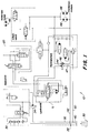
- FIG. 1 of the drawing includes a circuit diagram of a hydraulic system 10 that can be used on a vehicle 12 shown in FIG. 2.
- the spindle mower units 14, vehicle wheels 16, 26 and other vehicle components, such as a hydraulic steering aid 18 and a lifting device 20 for raising and lowering the spindle mower units 14, can be driven or operated via the hydraulic system 10.
- the vehicle 12 itself is also provided with an internal combustion engine 22 in an engine compartment 24, which is located in the front area of the vehicle between the two front Vehicle wheels 16 is provided.
- the rear vehicle wheel 26 is also steerable and has a vehicle seat 28 above it, while a hydraulic fluid reservoir 30 is provided at the rear end of the vehicle 12 between the vehicle seat 28 and the only rear vehicle wheel 26.
- the collecting container 30 is shown schematically in FIG. 1, from which it can be seen that a suction line 32 leads from this to a hydraulic gear pump 34 which is mounted in a front area of the vehicle 12.
- This gear pump 34 draws hydraulic fluid from the reservoir 30 for driving hydraulic motors 36 driving the spindle mowing units 14.
- a mower unit 14 is provided in front of the two front vehicle wheels 16 and a single mower unit in front of the rear vehicle wheel 26. Each mower unit 14 is driven by a separate hydraulic motor 36.
- Liquid emerging from the hydraulic motors 36 flows into a branch line 38 which has a first and a second branch 40 and 42.
- the first branch 40 is designed as a return line, which extends backwards to the collecting container 30 and discharges part of the liquid into the collecting container 30 for cooling purposes.
- the second branch 42 is connected to a charge pump 44 which supplies a hydrostatic pump 46 with liquid.
- the hydrostatic pump 46 drives the drivable vehicle wheels.
- Other vehicle components, such as the hydraulic steering aid 18 and the lifting mechanism 20, are charged with liquid from the charge pump 44.
- the hydrostatic pump 46 and the hydraulic motors 48 driving the vehicle wheels 16 and 26 basically work as a system separate from the rest of the hydraulic system 10. Both However, systems are chained together via the drain line 47 of the pump housing, which opens into the second return line 50, and via the charge pump 44, which presses liquid into the hydraulic system of the hydrostatic pump 46 in order to add liquid that has escaped through the drain line 47 replace.
- the second return line 50 returns liquid from the steering aid 18, the lifting mechanism 20 and from the drain line 47 to a location in the suction line 32 which is close to the gear pump 34, so that the return liquid from the return line 50 is fed directly to the gear pump 34, without first getting completely into the collecting container 30, which is far away from the gear pump. Since this return liquid is thus fed directly to the gear pump 34, the gear pump only sucks a relatively small amount of liquid through the suction line 32 from the remote collecting container 30. In addition, there is very little cavitation due to the pressure drop in the relatively long suction line 32.
- the gear pump 34 has a higher flow rate or capacity than the charge pump 44.
- the gear pump pumps a larger amount of liquid than the charge pump 44 is able to pump.
- the charge pump 44 cannot take up the entire amount pumped by the gear pump 34 and only takes up a part of the liquid conveyed by the gear pump 34 via the second branch 42.
- the liquid that is not required or sucked in by the charge pump gets into the first branch 40 and thus into the collecting container 30.
- the difference in the pump performance also ensures that part of the liquid is returned to the collecting container 30 via the first branch 40 for cooling purposes reached.
- the difference in the pump capacities ensures that part of the liquid which the gear pump 34 sucks comes out of the collecting container 30 via the suction line 32.
- the charge pump 44 delivers a smaller amount of liquid than the gear pump 34, so that the gear pump 34 requires more liquid than the charge pump 44 can provide via the second return line 50. Since only a part of the liquid required by the gear pump 34 can be made available via the second return line, the remaining amount is sucked out of the collecting container 30 via the suction line 32.
- the difference in pump capacities thus ensures that at least a small portion of the chilled liquid is drawn from the remote reservoir 30 and circulates in the system so that a relatively low liquid temperature can be maintained during operation.
- the collection container is located approximately 1 m from the gear pump 34 so that the suction line has a length of approximately 1 m.
- the gear pump has a capacity of 21.8 l per min (5.76 gal / min) or 6 cm3 per revolution (0.37 cu.in./rev) at 3600 rpm.
- the charge pump has a work rate of 5.65 1 / min (1.5 gal / min) at 56 at (800 psi) and 15.12 1 / min (4 gal / min) at 3.5 at (50 psi) .
- the hydrostatic pump 46 has a capacity of 45.4 to 68 l / min (12-18 gal / min).
- the preferred exemplary embodiment of the present invention is based on a hydraulic system 10, the collecting container 30 of which is arranged at some distance from the hot or at least warm engine compartment, so that the liquid in the collecting container is not heated by the engine and is therefore easier to cool is.
- the flow of the hydraulic fluid between the gear pump 34, which drives the motors 36 of the cylinder mower 14, and the charge pump 44, which drives the vehicle components 18 and 20, at least does so a reduction in the formation of cavitation, because the amount of liquid that is sucked in through the relatively long suction line 32 led to the collecting container 30 is reduced.
- the system with a gear pump and with a charge pump of lower capacity ensures that part of the liquid required in the system is fed directly into the collection container and sucked out of the collection container, so that the operating temperature of the liquid remains correspondingly low.
Landscapes
- Engineering & Computer Science (AREA)
- Physics & Mathematics (AREA)
- Fluid Mechanics (AREA)
- Mechanical Engineering (AREA)
- General Engineering & Computer Science (AREA)
- Harvester Elements (AREA)
Abstract
Description
- Die Erfindung bezieht sich auf ein hydraulisches System für ein Fahrzeug mit einem Sammelbehälter, einer ersten und einer zweiten Pumpe, einer den Sammelbehälter mit der ersten Pumpe verbindenden Saugleitung, einem ersten mit der ersten Pumpe verbundenen Treibmittel zum Antreiben einer ersten Fahrzeugkomponente, einem zweiten mit der zweiten Pumpe verbundenen Treibmittel zum Antreiben einer zweiten Fahrzeugkomponente und einer Rücklaufleitung für die zweite Pumpe.
- Dieses hydraulische System (US-A-5 069 037) ist für einen Rasentraktor konzipiert, der zwischen seinen vorderen und rückwärtigen Rädern mit einem Sichelmäher versehen ist. Die erste Pumpe gehört zu einem hydrostatischen Antrieb für die rückwärtigen Räder, während die zweite Pumpe Teil einer Hilfskraftlenkung ist und zum Druckbeaufschlagen von Hubzylindern dient. Beide Pumpen sind im Bereich eines rückwärtigen Fahrzeuggetriebes angeordnet, dessen Sumpf auch als Sammelbehälter für das hydraulische System dient, und haben einen eigenen hydraulischen Kreislauf mit einer gemeinsamen Saugleitung. Die Pumpen sind damit zueinander parallel geschaltet, so daß jede Pumpe den erforderlichen Flüssigkeitsbedarf gesondert ansaugt. Damit wird eine relativ große Flüssigkeitsmenge benötigt, auch wenn die Pumpen unterschiedliche Kapazitäten haben.
- Solche Systeme sind kavitationsanfällig, insbesondere bei langen Saugleitungen und Pumpen mit einem marginalen Einlaßvakuum. Es entstehen in der Flüssigkeit Hohlraumbildungen durch Gasauscheidungen im Unterdruckbereich. Es bilden sich Dampfbläschen und ein ansteigender Druck führt zur Kondensation dieser Dampfbläschen. Die dabei auftretende Volumensänderung ist mit sehr starken Druckstößen verbunden, die eine starke Schallabstrahlung verursachen und zu einer allmählichen Zerstörung benachbarter fester Teile führen.
- Andererseits gibt es auch hydraulische Systeme, die zum Antrieb von mehreren an einem Rasentraktor aufgehängten Sichelmähern dienen und die weniger kavitationsanfällig sind, weil sie relativ kompakt mit kurzen Leitungen ausgebildet sind. Die Sichelmäher sind dabei in der Regel vor der Maschine aufgehängt und werden durch eine Zahnradpumpe angetrieben. Ebenfalls im vorderen Fahrzeugbereich befindet sich eine an eine hydrostatische Pumpe angeschlossene Ladepumpe für den Antrieb der Fahrzeugräder und zum Betätigen anderer Fahrzeugkomponenten. Während des Einsatzes erhitzt sich die Flüssigkeit stark. Hinzu kommt das Hydraulikleitungen und andere hydraulische Komponenten relativ nah an dem sich ebenfalls im Einsatz aufheizenden Motorraum angeordnet sind, was ebenfalls zu einer zusätzlichen Erwärmung führt. Solche Systeme besitzen eine einzige Rücklaufleitung, die zu einem Sammelbehälter führt, der wegen der kompakten Bauweise ebenfalls im Frontbereich des Fahrzeuges vorgesehen ist. Damit kann wegen der Nähe zum Motor die Flüssigkeit nicht ausreichend gekühlt werden, sofern kein gesonderter Kühler vorgesehen ist. Ein solcher erhöht aber wiederum die Herstellungskosten.
- Die mit der Erfindung zu lösende Aufgabe wird dementsprechend in einem verbesserten hydraulischen System gesehen, das zumindest einige der vorstehend aufgeführten Nachteile vermeidet. Nach der Erfindung ist deshalb eine an den Ausgang des ersten Treibmittels angeschlossene Abzweigleitung mit einem ersten mit dem Sammelbehälter verbundenen Abzweig und einem zweiten an die zweite Pumpe angeschlossenen Abzweig vorgesehen, wobei die Rücklaufleitung mit der Saugleitung verbunden ist. Auf diese Weise ist die Abzweigleitung stromabwärts des ersten Treibmittels angeschlossen, und aus diesem ersten Treibmittel austretende Flüssigkeit wird aufgeteilt in zwei Teilströme, von denen einer in den Sammelbehälter und der andere zu der zweiten Pumpe gelangt. Flüssigkeit in der Rücklaufleitung gelangt unmittelbar zum Eingang der ersten Pumpe, ohne den Sammelbehälter durchlaufen zu müssen. Beide Pumpen sind damit zueinander in Reihe geschaltet, die zweite Pumpe saugt keine Flüssigkeit aus dem Sammelbehälter an, und der Gesamtflüssigkeitsbedarf des Systems ist damit reduziert.
- Vorteilhaft kann die erste Pumpe eine größere Kapazität als die zweite Pumpe aufweisen, so daß die Rücklaufmenge von der zweiten Pumpe nicht ausreicht, die erste Pumpe zu speisen, so daß diese gezwungen ist, in der Regel gekühlte Flüssigkeit zusätzlich aus dem Sammelbehälter anzusaugen, was aber für die zweite Pumpe nicht zutrifft. Beide Pumpen erhalten damit keine relativ kalte Flüssigkeit, wodurch die Viskosität erhöht und ein Ansaugen erschwert würde. Dennoch arbeiten beide Pumpen bei einer relativ niedrigen Betriebstemperatur.
- Das hydraulische System ist nach einem weiteren Vorschlag der Erfindung derart ausgelegt, daß im Einsatz der erste Abzweig ständig Flüssigkeit führend ist, damit Flüssigkeit zu Kühlzwecken in den Sammelbehälter zurückgeführt wird.
- Nach einem weiteren erfindungsgemäßen Vorschlag dient die Pumpe mit der größeren Leistung zum Antrieb mehrerer Spindelmäheinheiten, die die erste Fahrzeugkomponente bilden.
- Dieses hydraulische System ist besonders geeignet für ein Fahrzeug, das als Rasentraktor mit frontseitig vorgesehenem und Hitze entwickelndem Verbrennungsmotor ausgebildet ist, wobei der Sammelbehälter in einem rückwärtigen Fahrzeugbereich angeordnet ist und damit von der Hitzeentwicklung des Motors nicht beeinträchtigt wird. In einem solchen Fall können die erste und zweite Pumpe und die ersten und zweiten Treibmittel im frontseitigen Bereich des Rasentraktors angeordnet sein, ohne daß eine Überhitzung der Flüssigkeit zu befürchten ist, da der abgelegene Sammelbehälter auch ohne zusätzlichen Kühler für eine ausreichende Kühlung sorgt. Eine relativ kompakte Bauweise ist gegeben.
- In weiterer Fortbildung der Erfindung kann die zweite Pumpe als Ladepumpe ausgebildet und mit einer hydrostatischen Pumpe, die zum Antrieb mindestens eines Fahrzeugrades dient, verbunden sein, wobei das Gehäuse der hydrostatischen Pumpe eine Drainageleitung aufweist, die an die Rücklaufleitung angeschlossen ist. Der Kreislauf des hydrostatischen Antriebes ist geschlossen und nur mit der Ladepumpe verbunden, so daß Flüssigkeit nachgesaugt werden kann, um die Leckflüssigkeit, die durch die Drainageleitung in die Rücklaufleitung gelangt, auszugleichen. Außer diesen beiden Verbindungen sind die beiden Kreisläufe voneinander vollständig getrennt, wobei über die Ladepumpe noch andere Fahrzeugkomponenten, wie Hubzylinder und eine Hilfslenkung betrieben werden können.
- Um die Kavitationsgefahr noch weiter zu begrenzen, sieht die Erfindung schließlich vor, daß die Rücklaufleitung in unmittelbarer Nähe der ersten Pumpe in die Saugleitung mündet.
- In der Zeichnung ist ein Ausführungsbeispiel der Erfindung dargestellt. Es zeigt:
- Fig. 1
- ein hydraulisches System in schematischer Darstellung und
- Fig. 2
- einen insbesondere auf Golfplätzen einsetzbaren Spindelrasenmäher, an dem das hydraulische System realisiert ist.
- Fig. 1 der Zeichnung beinhaltet ein Schaltdiagramm eines hydraulischen Systems 10, das an einem in Fig. 2 gezeigten Fahrzeug 12 Verwendung finden kann. An einem derartigen Fahrzeug können hydraulisch antreibbare Spindelmäheinheiten 14 angeschlossen werden, wie sie zur Pflege von Golfplätzen oder dergleichen eingesetzt werden. Über das hydraulische System 10 sind die Spindelmäheinheiten 14, Fahrzeugräder 16, 26 und weitere Fahrzeugkomponenten, wie eine hydraulische Lenkhilfe 18 und eine Hubeinrichtung 20 zum Anheben und Absenken der Spindelmäheinheiten 14 an- bzw. betreibbar. Das Fahrzeug 12 selbst ist noch mit einem Verbrennungsmotor 22 in einem Motorraum 24 versehen, der im vorderen Bereich des Fahrzeuges zwischen den beiden vorderen Fahrzeugrädern 16 vorgesehen ist. Das rückwärtige Fahrzeugrad 26 ist außerdem lenkbar und über ihm befindet sich ein Fahrzeugsitz 28, während ein Sammelbehälter 30 für hydraulische Flüssigkeit an dem rückwärtigen Ende des Fahrzeuges 12 zwischen dem Fahrzeugsitz 28 und dem einzigen rückwärtigen Fahrzeugrad 26 vorgesehen ist. Der Sammelbehälter 30 ist schematisch in Fig. 1 eingezeichnet, aus der zu erkennen ist, daß von diesem eine Saugleitung 32 zu einer hydraulischen Zahnradpumpe 34 führt, die in einem vorderen Bereich des Fahrzeuges 12 montiert ist. Diese Zahnradpumpe 34 saugt hydraulische Flüssigkeit aus dem Sammelbehälter 30 für den Antrieb von die Spindelmäheinheiten 14 antreibenden Hydromotoren 36 an. Beim Ausführungsbeispiel sind je eine Mäheinheit 14 vor den beiden vorderen Fahrzeugrädern 16 und eine einzige Mäheinheit vor dem rückwärtigen Fahrzeugrad 26 vorgesehen. Jede Mäheinheit 14 wird über einen gesonderten Hydromotor 36 angetrieben. Aus den Hydromotoren 36 austretende Flüssigkeit fließt in eine Abzweigleitung 38, die einen ersten und einen zweiten Abzweig 40 und 42 aufweist. Hierbei ist der erste Abzweig 40 als Rücklaufleitung ausgebildet, die sich nach rückwärts bis zu den Sammelbehälter 30 erstreckt und einen Teil der Flüssigkeit zu Kühlzwecken in den Sammelbehälter 30 abführt. Der zweite Abzweig 42 ist an eine Ladepumpe 44 angeschlossen, die eine hydrostatische Pumpe 46 mit Flüssigkeit beliefert. Die hydrostatische Pumpe 46 treibt die antreibbaren Fahrzeugräder an. Andere Fahrzeugkomponenten, wie die hydraulische Lenkhilfe 18 und der Hebemechanismus 20 werden von der Ladepumpe 44 aus mit Flüssigkeit beschickt. Aus der Lenkhilfe 18 und aus dem Hebemechanismus 20 austretende Flüssigkeit sowie aus dem Pumpengehäuse durch eine Drainageleitung 47 austretende Flüssigkeit gelangt in eine zweite Rücklaufleitung 50, die ihrerseits an die Saugleitung 32 angeschlossen ist und zwar an einer Stelle, die zwischen der Zahnradpumpe 34 und dem Sammelbehälter 30 liegt.
- Die hydrostatische Pumpe 46 und die Fahrzeugräder 16 und 26 antreibende Hydromotore 48 arbeiten grundsätzlich als ein von dem übrigen hydraulischen System 10 getrenntes System. Beide Systeme sind allerdings über die Drainageleitung 47 des Pumpengehäuses, die in die zweite Rücklaufleitung 50 mündet, und über die Ladepumpe 44 miteinander verkettet, die Flüssigkeit in das hydraulische System der hydrostatischen Pumpe 46 drückt, um Flüssigkeit, die durch die Drainageleitung 47 ausgetreten ist, zu ersetzen.
- Die zweite Rücklaufleitung 50 führt Flüssigkeit aus der Lenkhilfe 18, dem Hebemechanismus 20 und aus der Drainageleitung 47 zu einer Stelle in der Saugleitung 32 zurück, die nahe der Zahnradpumpe 34 liegt, so daß die Rücklaufflüssigkeit aus der Rücklaufleitung 50 direkt der Zahnradpumpe 34 zugefördert wird, ohne zunächst vollständig in den von der Zahnradpumpe weit entfernt liegenden Sammelbehälter 30 zu gelangen. Da somit diese Rücklaufflüssigkeit direkt der Zahnradpumpe 34 zugeführt wird, saugt die Zahnradpumpe lediglich eine relativ kleine Menge Flüssigkeit durch die Saugleitung 32 aus dem abgelegenen Sammelbehälter 30 an. Außerdem tritt nur eine äußerst geringe Kavitation infolge des Druckabfalls in der relativ langen Saugleitung 32 auf.
- Andererseits wird nicht die gesamte Flüssigkeitsmenge aus der Rücklaufleitung 50 der Zahnradpumpe 34 zugeführt, da das System so ausgebildet ist, daß ein Teil dieser Flüssigkeit zu Kühlzwecken in den Sammelbehälter 30 geleitet wird. Die Zahnradpumpe 34 hat im Einsatz eine höhere Durchflußrate oder Kapazität als die Ladepumpe 44. Die Zahnradpumpe pumpt nämlich eine größere Menge Flüssigkeit als die Ladepumpe 44 in der Lage ist zu pumpen. Die Ladepumpe 44 kann nicht die gesamte von der Zahnradpumpe 34 gepumpte Menge aufnehmen und nimmt nur einen Teil der von der Zahnradpumpe 34 geförderten Flüssigkeit über den zweiten Abzweig 42 auf. Die von der Ladepumpe nicht benötigte oder angesaugte Flüssigkeit gelangt in den ersten Abzweig 40 und damit in den Sammelbehälter 30. Der Unterschied in der Pumpenleistung stellt damit auch sicher, daß ein Teil der Flüssigkeit zu Kühlzwecken über den ersten Abzweig 40 wieder zurück in den Sammelbehälter 30 gelangt.
- In gleicher Weise stellt der Unterschied in den Pumpenkapazitäten sicher, daß ein Teil der Flüssigkeit, den die Zahnradpumpe 34 ansaugt, über die Saugleitung 32 aus dem Sammelbehälter 30 kommt. Die Ladepumpe 44 fördert eine kleinere Menge Flüssigkeit als die Zahnradpumpe 34 , so daß die Zahnradpumpe 34 mehr Flüssigkeit benötigt, als die Ladepumpe 44 über die zweite Rücklaufleitung 50 zur Verfügung stellen kann. Da nur ein Teil der von der Zahnradpumpe 34 benötigten Flüssigkeit über die zweite Rücklaufleitung zur Verfügung gestellt werden kann, wird die verbleibende Restmenge aus dem Sammelbehälter 30 über die Saugleitung 32 angesaugt. Der Unterschied in den Pumpenkapazitäten stellt damit sicher, daß zumindest ein kleiner Teil gekühlter Flüssigkeit aus dem entfernt liegenden Sammelbehälter 30 angesaugt wird und in dem System zirkuliert, damit während des Betriebes eine relativ niedrige Flüssigkeitstemperatur aufrechterhalten bleiben kann.
- Bei dem bevorzugten Ausführungsbeispiel der vorliegenden Erfindung ist der Sammelbehälter etwa 1 m von der Zahnradpumpe 34 entfernt angeordnet, do daß die Saugleitung eine Länge von etwa 1 m hat. Die Zahnradpumpe hat eine Kapazität von 21,8 l pro min (5,76 gal/min) oder von 6 cm³ pro Umdrehung (0,37 cu.in./rev) bei 3600 U/min. Die Ladepumpe hat eine Arbeitsleistung von 5,65 1/min (1,5 gal/min) bei 56 at (800 psi) und von 15,12 1/min (4 gal/min) bei 3,5 at (50 psi). Die hydrostatische Pumpe 46 hat eine Kapazität von 45,4 bis 68 l/min (12-18 gal/min).
- Dem bevorzugten Ausführungsbeispiel der vorliegenden Erfindung liegt damit ein hydraulisches System 10 zugrunde, dessen Sammelbehälter 30 mit einigem Abstand zu dem im Einsatz heißen oder zumindest warmen Motorraum angeordnet ist, so daß die sich im Sammelbehälter befindliche Flüssigkeit durch den Motor nicht aufgeheizt wird und deshalb besser kühlbar ist. Das Leiten der hydraulischen Flüssigkeit zwischen der Zahnradpumpe 34, die die Motoren 36 der Spindelmäher 14 antreibt, und der Ladepumpe 44, die die Fahrzeugkomponenten 18 und 20 antreibt, bewirkt zumindest eine Minderung der Kavitationsbildung, weil die Flüssigkeitsmenge, die durch die relativ lange zum Sammelbehälter 30 geführte Saugleitung 32 angesaugt wird, reduziert ist. Das System mit einer Zahnradpumpe und mit einer Ladepumpe von geringerer Kapazität stellt sicher, daß ein Teil der im System benötigten Flüssigkeit direkt in den Sammelbehälter geleitet und aus dem Sammelbehälter gesaugt wird, so daß die Betriebstemperatur der Flüssigkeit entsprechend niedrig bleibt.
Claims (7)
- Hydraulisches System für ein Fahrzeug (12) mit einem Sammelbehälter (30), einer ersten und einer zweiten Pumpe (34 und 44), einer den Sammelbehälter (30) mit der ersten Pumpe (34) verbindenden Saugleitung (32), einem ersten mit der ersten Pumpe (34) verbundenen Treibmittel (36) zum Antreiben einer ersten Fahrzeugkomponente, einem zweiten mit der zweiten Pumpe (44) verbundenen Treibmittel (46) zum Antreiben einer zweiten Fahrzeugkomponente und einer Rücklaufleitung (50) für die zweite Pumpe (44), gekennzeichnet durch eine an den Ausgang des ersten Treibmittels (34) angeschlossene Abzweigleitung (38) mit einem ersten mit dem Sammelbehälter (30) verbundenen Abzweig (40) und einem zweiten an die zweite Pumpe (44) angeschlossenen Abzweig (42), wobei die Rücklaufleitung (50) mit der Saugleitung (32) verbunden ist.
- Hydraulisches System nach Anspruch 1, dadurch gekennzeichnet, daß die erste Pumpe (34) eine größere Kapazität als die zweite Pumpe (44) hat.
- Hydraulisches System nach Anspruch 1 oder 2, dadurch gekennzeichnet, daß im Einsatz der erste Abzweig (40) ständig Flüssigkeit führend ist.
- Hydraulisches System nach einem oder mehreren der vorherigen Ansprüche, dadurch gekennzeichnet, daß die erste Fahrzeugkomponente aus mehreren Spindelmäheinheiten (14) besteht.
- Hydraulisches System nach einem oder mehreren der vorherigen Ansprüche, wobei das Fahrzeug (12) als Rasentraktor mit frontseitig vorgesehenem Verbrennungsmotor (20) ausgebildet und der Sammelbehälter (30) in einem rückwärtigen Fahrzeugbereich angeordnet ist, dadurch gekennzeichnet, daß die erste und zweite Pumpe (34 und 44) und die ersten und zweiten Treibmittel (36, 46) im frontseitigen Bereich des Rasentraktors angeordnet sind.
- Hydraulisches System nach einem oder mehreren der vorherigen Ansprüche, dadurch gekennzeichnet, daß die zweite Pumpe als Ladepumpe (44) ausgebildet ist und mit einer hydrostatischen Pumpe (46), die zum Antrieb mindestens eines Fahrzeugrades (16, 26) dient, verbunden ist, wobei das Gehäuse der hydrostatischen Pumpe (46) eine Drainageleitung (47) aufweist, die an die Rücklaufleitung (50) angeschlossen ist.
- Hydraulisches System nach einem oder mehreren der vorherigen Ansprüche, dadurch gekennzeichnet, daß die Rücklaufleitung (50) in unmittelbarer Nähe der ersten Pumpe (34) in die Saugleitung (32) mündet.
Applications Claiming Priority (2)
| Application Number | Priority Date | Filing Date | Title |
|---|---|---|---|
| US08/006,897 US5335494A (en) | 1993-01-21 | 1993-01-21 | Hydraulic system for reel mower vehicles |
| US6897 | 1993-01-21 |
Publications (2)
| Publication Number | Publication Date |
|---|---|
| EP0607604A1 true EP0607604A1 (de) | 1994-07-27 |
| EP0607604B1 EP0607604B1 (de) | 1997-03-12 |
Family
ID=21723159
Family Applications (1)
| Application Number | Title | Priority Date | Filing Date |
|---|---|---|---|
| EP93120792A Expired - Lifetime EP0607604B1 (de) | 1993-01-21 | 1993-12-23 | Hydraulisches System für ein Fahrzeug |
Country Status (4)
| Country | Link |
|---|---|
| US (1) | US5335494A (de) |
| EP (1) | EP0607604B1 (de) |
| CA (1) | CA2109291C (de) |
| DE (1) | DE59305767D1 (de) |
Families Citing this family (9)
| Publication number | Priority date | Publication date | Assignee | Title |
|---|---|---|---|---|
| US5533325A (en) * | 1994-02-03 | 1996-07-09 | The Toro Company | All wheel hydraulic drive system |
| JP3430662B2 (ja) * | 1994-09-21 | 2003-07-28 | 日産自動車株式会社 | 車両の駆動力伝達装置 |
| JP3013225B2 (ja) * | 1995-01-11 | 2000-02-28 | 新キャタピラー三菱株式会社 | 吊り作業制御装置 |
| US6018895A (en) * | 1996-03-28 | 2000-02-01 | Clark Equipment Company | Valve stack in a mini-excavator directing fluid under pressure from multiple pumps to actuable elements |
| AU720849B2 (en) * | 1996-03-28 | 2000-06-15 | Clark Equipment Company | Multifunction valve stack |
| US5810110A (en) * | 1996-11-08 | 1998-09-22 | R. H. Sheppard Co., Inc. | Tandem power steering system with heat sink |
| US6182588B1 (en) * | 1998-05-01 | 2001-02-06 | Flexi-Coil Ltd. | Hydraulic system having boost pump in series with a primary pump and a boost pump drive therefor |
| US7401465B2 (en) * | 2005-11-16 | 2008-07-22 | Deere & Company | Dual pump dual pressure hydraulic circuit |
| US7568331B2 (en) * | 2005-12-21 | 2009-08-04 | Deere & Company | Extendable lift arms for trim mower |
Citations (4)
| Publication number | Priority date | Publication date | Assignee | Title |
|---|---|---|---|---|
| US3962870A (en) * | 1975-04-23 | 1976-06-15 | International Harvester Company | Variable volume dual pump circuit |
| DE3222106A1 (de) * | 1982-06-11 | 1983-12-15 | Robert Bosch Gmbh, 7000 Stuttgart | Hydraulische steuereinrichtung |
| DE3406228A1 (de) * | 1984-02-21 | 1985-08-29 | Mannesmann Rexroth GmbH, 8770 Lohr | Hydrauliksystem fuer einen landwirtschaftlichen schlepper |
| US5069037A (en) * | 1989-12-05 | 1991-12-03 | Kanzaki Kokyukoki Mfg. Co., Ltd. | Fluid supply system for vehicles |
Family Cites Families (11)
| Publication number | Priority date | Publication date | Assignee | Title |
|---|---|---|---|---|
| US3032994A (en) * | 1959-12-14 | 1962-05-08 | Koehring Co | Hydraulic drive for trenching machine |
| US3360925A (en) * | 1966-02-03 | 1968-01-02 | Int Harvester Co | Multiple speed hydraulic control system |
| US3785157A (en) * | 1972-11-24 | 1974-01-15 | Deere & Co | Flow control dump valve |
| US3913453A (en) * | 1974-08-30 | 1975-10-21 | Deere & Co | Hydrostatic transmission |
| US3915068A (en) * | 1974-08-30 | 1975-10-28 | Deere & Co | Hydrostatic transmission |
| US3952510A (en) * | 1975-06-06 | 1976-04-27 | Caterpillar Tractor Co. | Flow sensing and control apparatus |
| JPS55120802U (de) * | 1979-02-20 | 1980-08-27 | ||
| JPS58135551U (ja) * | 1982-03-09 | 1983-09-12 | 株式会社クボタ | トラクタの駆動構造 |
| US4531368A (en) * | 1983-12-19 | 1985-07-30 | Deere & Company | Reservoir for a multi-pump hydraulic system |
| JPH07116721B2 (ja) * | 1989-01-31 | 1995-12-13 | 油谷重工株式会社 | 油圧ショベルの油圧回路 |
| JPH02236002A (ja) * | 1989-03-08 | 1990-09-18 | Kubota Ltd | 作業車の昇降用油圧回路 |
-
1993
- 1993-01-21 US US08/006,897 patent/US5335494A/en not_active Expired - Lifetime
- 1993-10-26 CA CA002109291A patent/CA2109291C/en not_active Expired - Fee Related
- 1993-12-23 EP EP93120792A patent/EP0607604B1/de not_active Expired - Lifetime
- 1993-12-23 DE DE59305767T patent/DE59305767D1/de not_active Expired - Fee Related
Patent Citations (4)
| Publication number | Priority date | Publication date | Assignee | Title |
|---|---|---|---|---|
| US3962870A (en) * | 1975-04-23 | 1976-06-15 | International Harvester Company | Variable volume dual pump circuit |
| DE3222106A1 (de) * | 1982-06-11 | 1983-12-15 | Robert Bosch Gmbh, 7000 Stuttgart | Hydraulische steuereinrichtung |
| DE3406228A1 (de) * | 1984-02-21 | 1985-08-29 | Mannesmann Rexroth GmbH, 8770 Lohr | Hydrauliksystem fuer einen landwirtschaftlichen schlepper |
| US5069037A (en) * | 1989-12-05 | 1991-12-03 | Kanzaki Kokyukoki Mfg. Co., Ltd. | Fluid supply system for vehicles |
Also Published As
| Publication number | Publication date |
|---|---|
| CA2109291C (en) | 1996-09-10 |
| DE59305767D1 (de) | 1997-04-17 |
| US5335494A (en) | 1994-08-09 |
| CA2109291A1 (en) | 1994-07-22 |
| EP0607604B1 (de) | 1997-03-12 |
Similar Documents
| Publication | Publication Date | Title |
|---|---|---|
| EP1055359B1 (de) | Gerät zum Anbau an ein Trägerfahrzeug | |
| DE69528078T2 (de) | Hydraulikmotorsystem | |
| EP0054792A2 (de) | Kühleinrichtung zur Kühlung einer Brennkraftmaschine und der Ladeluft | |
| EP0607604B1 (de) | Hydraulisches System für ein Fahrzeug | |
| EP2759192A1 (de) | Zusatzgerät für eine landwirtschaftliche Arbeitsmaschine | |
| EP0446757B1 (de) | Hydrauliksystem zur Versorgung einer Verstellpumpe | |
| EP0149800B1 (de) | Sammelbehälter für Öl einer hydraulischen Anlage | |
| DE602004012570T2 (de) | Hst-antriebseinheit | |
| WO2024256128A1 (de) | Kühl- und schmiersystem | |
| WO2024052400A1 (de) | Pumpensystem für einen elektrischen achsantrieb | |
| EP1443220B1 (de) | Hydraulischer Kreislauf und Spülvorrichtung | |
| DE3931699C2 (de) | ||
| EP2280197B1 (de) | Hydrostatischer Mehrmotorenantrieb | |
| EP0691234B2 (de) | Verfahren und Einrichtung zur Kühlung mindestens einer Fahrpumpe und mindestens eines Fahrmotors eines hydrostatischen Fahrantriebes | |
| DE2457210B2 (de) | Hydrostatischer zusatzantrieb fuer die lenkbaren antriebsraeder eines fahrzeuges, insbesondere eines schleppers | |
| DE9411163U1 (de) | Einrichtung zur Kühlung mindestens einer Fahrpumpe und/oder mindestens eines Fahrmotors eines hydrostatischen Fahrantriebes | |
| DE1425744A1 (de) | Statisches Druckfluidumgetriebe und Kreislaufsystem dazu | |
| EP3597879B1 (de) | Landwirtschaftliche maschine mit einem kühlsystem | |
| EP1827891B1 (de) | Hydrostatischer fahrantrieb mit differentialsperrwirkung | |
| AT307121B (de) | Mähwerksantrieb bei Ackerschleppern | |
| DE1555926C3 (de) | Druckversorgungseinrichtung für hydrostatische Lenkeinrichtungen von Fahrzeugen, insbesondere Schleppern | |
| DE102024208775A1 (de) | Versorgungssystem für eine eine elektrische Maschine aufweisende Vorrichtung sowie elektrisch antreibbare Fahrzeugachse | |
| DE102009045082A1 (de) | Verfahren und Einrichtung zum Kühlen des Getriebeöls eines Kraftfahrzeug-Getriebes | |
| DE102023005204A1 (de) | Elektrische Antriebseinrichtung für ein Kraftfahrzeug, insbesondere für einen Kraftwagen | |
| DE102024208774A1 (de) | Versorgungssystem für eine eine elektrische Maschine aufweisende Vorrichtung sowie elektrisch antreibbare Fahrzeugachse |
Legal Events
| Date | Code | Title | Description |
|---|---|---|---|
| PUAI | Public reference made under article 153(3) epc to a published international application that has entered the european phase |
Free format text: ORIGINAL CODE: 0009012 |
|
| AK | Designated contracting states |
Kind code of ref document: A1 Designated state(s): DE FR GB IT |
|
| 17P | Request for examination filed |
Effective date: 19940623 |
|
| 17Q | First examination report despatched |
Effective date: 19960315 |
|
| GRAG | Despatch of communication of intention to grant |
Free format text: ORIGINAL CODE: EPIDOS AGRA |
|
| GRAH | Despatch of communication of intention to grant a patent |
Free format text: ORIGINAL CODE: EPIDOS IGRA |
|
| GRAH | Despatch of communication of intention to grant a patent |
Free format text: ORIGINAL CODE: EPIDOS IGRA |
|
| GRAA | (expected) grant |
Free format text: ORIGINAL CODE: 0009210 |
|
| AK | Designated contracting states |
Kind code of ref document: B1 Designated state(s): DE FR GB IT |
|
| GBT | Gb: translation of ep patent filed (gb section 77(6)(a)/1977) |
Effective date: 19970313 |
|
| REF | Corresponds to: |
Ref document number: 59305767 Country of ref document: DE Date of ref document: 19970417 |
|
| ET | Fr: translation filed | ||
| ITF | It: translation for a ep patent filed | ||
| PLBE | No opposition filed within time limit |
Free format text: ORIGINAL CODE: 0009261 |
|
| STAA | Information on the status of an ep patent application or granted ep patent |
Free format text: STATUS: NO OPPOSITION FILED WITHIN TIME LIMIT |
|
| 26N | No opposition filed | ||
| REG | Reference to a national code |
Ref country code: GB Ref legal event code: IF02 |
|
| PGFP | Annual fee paid to national office [announced via postgrant information from national office to epo] |
Ref country code: IT Payment date: 20061231 Year of fee payment: 14 |
|
| PGFP | Annual fee paid to national office [announced via postgrant information from national office to epo] |
Ref country code: FR Payment date: 20071217 Year of fee payment: 15 |
|
| PGFP | Annual fee paid to national office [announced via postgrant information from national office to epo] |
Ref country code: DE Payment date: 20081120 Year of fee payment: 16 |
|
| PG25 | Lapsed in a contracting state [announced via postgrant information from national office to epo] |
Ref country code: IT Free format text: LAPSE BECAUSE OF NON-PAYMENT OF DUE FEES Effective date: 20071223 |
|
| REG | Reference to a national code |
Ref country code: FR Ref legal event code: ST Effective date: 20090831 |
|
| PG25 | Lapsed in a contracting state [announced via postgrant information from national office to epo] |
Ref country code: FR Free format text: LAPSE BECAUSE OF NON-PAYMENT OF DUE FEES Effective date: 20081231 |
|
| PG25 | Lapsed in a contracting state [announced via postgrant information from national office to epo] |
Ref country code: DE Free format text: LAPSE BECAUSE OF NON-PAYMENT OF DUE FEES Effective date: 20100701 |
|
| PGFP | Annual fee paid to national office [announced via postgrant information from national office to epo] |
Ref country code: GB Payment date: 20121227 Year of fee payment: 20 |
|
| REG | Reference to a national code |
Ref country code: GB Ref legal event code: PE20 Expiry date: 20131222 |
|
| PG25 | Lapsed in a contracting state [announced via postgrant information from national office to epo] |
Ref country code: GB Free format text: LAPSE BECAUSE OF EXPIRATION OF PROTECTION Effective date: 20131222 |