EP0607610A1 - Kugelgelenk und Arbeitsverfahren zu seiner Herstellung - Google Patents
Kugelgelenk und Arbeitsverfahren zu seiner Herstellung Download PDFInfo
- Publication number
- EP0607610A1 EP0607610A1 EP93120900A EP93120900A EP0607610A1 EP 0607610 A1 EP0607610 A1 EP 0607610A1 EP 93120900 A EP93120900 A EP 93120900A EP 93120900 A EP93120900 A EP 93120900A EP 0607610 A1 EP0607610 A1 EP 0607610A1
- Authority
- EP
- European Patent Office
- Prior art keywords
- housing
- ball joint
- ball
- pin
- sheet metal
- Prior art date
- Legal status (The legal status is an assumption and is not a legal conclusion. Google has not performed a legal analysis and makes no representation as to the accuracy of the status listed.)
- Granted
Links
- 238000000034 method Methods 0.000 title claims abstract description 11
- 238000004519 manufacturing process Methods 0.000 title claims abstract description 6
- 239000000463 material Substances 0.000 claims abstract description 10
- 239000011324 bead Substances 0.000 claims abstract description 8
- 239000002184 metal Substances 0.000 claims abstract description 8
- 238000007789 sealing Methods 0.000 claims abstract description 6
- 238000005520 cutting process Methods 0.000 claims description 4
- 238000006073 displacement reaction Methods 0.000 claims description 2
- 238000003754 machining Methods 0.000 abstract description 2
- 238000005096 rolling process Methods 0.000 description 4
- 238000007493 shaping process Methods 0.000 description 2
- 241000309551 Arthraxon hispidus Species 0.000 description 1
- 239000007769 metal material Substances 0.000 description 1
- 230000007704 transition Effects 0.000 description 1
- 238000003466 welding Methods 0.000 description 1
Images
Classifications
-
- F—MECHANICAL ENGINEERING; LIGHTING; HEATING; WEAPONS; BLASTING
- F16—ENGINEERING ELEMENTS AND UNITS; GENERAL MEASURES FOR PRODUCING AND MAINTAINING EFFECTIVE FUNCTIONING OF MACHINES OR INSTALLATIONS; THERMAL INSULATION IN GENERAL
- F16C—SHAFTS; FLEXIBLE SHAFTS; ELEMENTS OR CRANKSHAFT MECHANISMS; ROTARY BODIES OTHER THAN GEARING ELEMENTS; BEARINGS
- F16C11/00—Pivots; Pivotal connections
- F16C11/04—Pivotal connections
- F16C11/06—Ball-joints; Other joints having more than one degree of angular freedom, i.e. universal joints
- F16C11/0619—Ball-joints; Other joints having more than one degree of angular freedom, i.e. universal joints the female part comprising a blind socket receiving the male part
- F16C11/0623—Construction or details of the socket member
-
- F—MECHANICAL ENGINEERING; LIGHTING; HEATING; WEAPONS; BLASTING
- F16—ENGINEERING ELEMENTS AND UNITS; GENERAL MEASURES FOR PRODUCING AND MAINTAINING EFFECTIVE FUNCTIONING OF MACHINES OR INSTALLATIONS; THERMAL INSULATION IN GENERAL
- F16C—SHAFTS; FLEXIBLE SHAFTS; ELEMENTS OR CRANKSHAFT MECHANISMS; ROTARY BODIES OTHER THAN GEARING ELEMENTS; BEARINGS
- F16C11/00—Pivots; Pivotal connections
- F16C11/04—Pivotal connections
- F16C11/06—Ball-joints; Other joints having more than one degree of angular freedom, i.e. universal joints
-
- F—MECHANICAL ENGINEERING; LIGHTING; HEATING; WEAPONS; BLASTING
- F16—ENGINEERING ELEMENTS AND UNITS; GENERAL MEASURES FOR PRODUCING AND MAINTAINING EFFECTIVE FUNCTIONING OF MACHINES OR INSTALLATIONS; THERMAL INSULATION IN GENERAL
- F16C—SHAFTS; FLEXIBLE SHAFTS; ELEMENTS OR CRANKSHAFT MECHANISMS; ROTARY BODIES OTHER THAN GEARING ELEMENTS; BEARINGS
- F16C11/00—Pivots; Pivotal connections
- F16C11/04—Pivotal connections
- F16C11/06—Ball-joints; Other joints having more than one degree of angular freedom, i.e. universal joints
- F16C11/0666—Sealing means between the socket and the inner member shaft
- F16C11/0671—Sealing means between the socket and the inner member shaft allowing operative relative movement of joint parts due to flexing of the sealing means
-
- F—MECHANICAL ENGINEERING; LIGHTING; HEATING; WEAPONS; BLASTING
- F16—ENGINEERING ELEMENTS AND UNITS; GENERAL MEASURES FOR PRODUCING AND MAINTAINING EFFECTIVE FUNCTIONING OF MACHINES OR INSTALLATIONS; THERMAL INSULATION IN GENERAL
- F16C—SHAFTS; FLEXIBLE SHAFTS; ELEMENTS OR CRANKSHAFT MECHANISMS; ROTARY BODIES OTHER THAN GEARING ELEMENTS; BEARINGS
- F16C7/00—Connecting-rods or like links pivoted at both ends; Construction of connecting-rod heads
- F16C7/08—Connecting-rods or like links pivoted at both ends; Construction of connecting-rod heads made from sheet metal
-
- Y—GENERAL TAGGING OF NEW TECHNOLOGICAL DEVELOPMENTS; GENERAL TAGGING OF CROSS-SECTIONAL TECHNOLOGIES SPANNING OVER SEVERAL SECTIONS OF THE IPC; TECHNICAL SUBJECTS COVERED BY FORMER USPC CROSS-REFERENCE ART COLLECTIONS [XRACs] AND DIGESTS
- Y10—TECHNICAL SUBJECTS COVERED BY FORMER USPC
- Y10T—TECHNICAL SUBJECTS COVERED BY FORMER US CLASSIFICATION
- Y10T29/00—Metal working
- Y10T29/49—Method of mechanical manufacture
- Y10T29/49826—Assembling or joining
- Y10T29/4984—Retaining clearance for motion between assembled parts
- Y10T29/49845—Retaining clearance for motion between assembled parts by deforming interlock
- Y10T29/49853—Retaining clearance for motion between assembled parts by deforming interlock of sphere, i.e., ball, in socket
-
- Y—GENERAL TAGGING OF NEW TECHNOLOGICAL DEVELOPMENTS; GENERAL TAGGING OF CROSS-SECTIONAL TECHNOLOGIES SPANNING OVER SEVERAL SECTIONS OF THE IPC; TECHNICAL SUBJECTS COVERED BY FORMER USPC CROSS-REFERENCE ART COLLECTIONS [XRACs] AND DIGESTS
- Y10—TECHNICAL SUBJECTS COVERED BY FORMER USPC
- Y10T—TECHNICAL SUBJECTS COVERED BY FORMER US CLASSIFICATION
- Y10T403/00—Joints and connections
- Y10T403/32—Articulated members
- Y10T403/32114—Articulated members including static joint
- Y10T403/32196—Articulate joint is ball and socket
- Y10T403/32204—Articulate joint is ball and socket with threaded joint
-
- Y—GENERAL TAGGING OF NEW TECHNOLOGICAL DEVELOPMENTS; GENERAL TAGGING OF CROSS-SECTIONAL TECHNOLOGIES SPANNING OVER SEVERAL SECTIONS OF THE IPC; TECHNICAL SUBJECTS COVERED BY FORMER USPC CROSS-REFERENCE ART COLLECTIONS [XRACs] AND DIGESTS
- Y10—TECHNICAL SUBJECTS COVERED BY FORMER USPC
- Y10T—TECHNICAL SUBJECTS COVERED BY FORMER US CLASSIFICATION
- Y10T403/00—Joints and connections
- Y10T403/32—Articulated members
- Y10T403/32606—Pivoted
- Y10T403/32631—Universal ball and socket
-
- Y—GENERAL TAGGING OF NEW TECHNOLOGICAL DEVELOPMENTS; GENERAL TAGGING OF CROSS-SECTIONAL TECHNOLOGIES SPANNING OVER SEVERAL SECTIONS OF THE IPC; TECHNICAL SUBJECTS COVERED BY FORMER USPC CROSS-REFERENCE ART COLLECTIONS [XRACs] AND DIGESTS
- Y10—TECHNICAL SUBJECTS COVERED BY FORMER USPC
- Y10T—TECHNICAL SUBJECTS COVERED BY FORMER US CLASSIFICATION
- Y10T403/00—Joints and connections
- Y10T403/32—Articulated members
- Y10T403/32606—Pivoted
- Y10T403/32631—Universal ball and socket
- Y10T403/32737—Universal ball and socket including liner, shim, or discrete seat
Definitions
- the invention relates to a ball joint according to the preamble of patent claim 1.
- a ball joint is known, the housing of which is made from several sheet metal parts by shaping, non-cutting machining.
- the individual parts are inseparably connected by a closed ring bead welding and, on the other hand, locked by a large number of clamps.
- a narrow ring is required to manufacture the joint, which takes over a centering function for the housing parts.
- the invention has for its object to provide a ball joint, the housing can be made in one piece and without cutting.
- the goal is to develop an easily manufactured, reduced-weight and easy-to-assemble ball joint with a sheet metal housing.
- the ball joint housing is produced by sheet metal forming, primarily in the deep-drawing process, in several successive operations.
- the invention provides for the production of such a ball joint a working method according to claim 2.
- the cylindrical housing part for receiving the bearing shell and the ball pin is first stamped into the cut housing plate.
- a soft, preferably metallic material is used to manufacture the ball joint housing, constructive measures to increase the stability are necessary according to the invention.
- lateral projections are formed as stiffening ribs when viewed from above.
- the shaft advantageously has a profile which is U-shaped in cross section. Other cross-sectional geometries, for example circular or triangular, are also possible.
- the length of the shaft depends on the intended use of the ball joint.
- a special feature of the assembly of the individual parts is the attachment of the housing cover. This is first inserted into the groove provided on the inner circumference of the housing. It is in direct contact with the bearing shell because it fixes it in its position.
- a wedge-shaped tool is subsequently used to indent the edge-side bead on the housing, which is worked out during the shaping process, with subsequent locking of the housing cover by material deformation of the notched material.
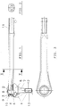
- An embodiment of the invention is shown as a ball joint of a tie rod for motor vehicles in the drawing. Show it: Figure 1: 2 shows a side view of a tie rod for motor vehicles with partial sectional segments: a section along the line II-II of Figure 1 Figure 3: a plan view of the tie rod for motor vehicles shown in Figure 1.
- FIG. 1 The embodiment of a tie rod for motor vehicles shown in FIG. 1 consists of a ball pin (1) which is movably mounted on all sides with a joint ball (2) connected to it in a bearing shell (3) and a ball joint housing (4) which holds the bearing shell in a cup-shaped area.
- a shaft (7) is connected to the joint ball (2) of the ball pin (1) and to this a thread (12) for connection in the motor vehicle.
- the ball pin comes out of the ball joint housing (4) on one side.
- the ball joint housing (4) on the exit side of the ball pin shaft (7) is deformed in the direction of the center axis (13) of the ball pin (1).
- the housing is closed by means of a housing cover (8) which also serves to secure the bearing shell against axial displacement.
- the housing cover is locked in the housing by a material deformation (9) of the edge bead (10).
- a wedge-shaped tool is used to split the edge bead at least partially in the radial direction.
- the radially inner area of the notched material is then deformed in such a way that the housing cover (8) is fixed on the ball joint housing.
- a sealing bellows (5) lies on the housing side in an annular groove (6) on the outer circumference of the housing. According to the invention, this annular groove is formed either during the deep-drawing process or immediately afterwards by a rolling process.
- the opposite side of the sealing bellows seals on the shaft (7) of the ball pin in a manner known per se.
- the ball joint housing has a connection area (11) on the side opposite the ball pin, which is provided with a thread.
- connection area (11) is designed.
- the internal thread can also be replaced by an external thread according to the respective component requirements. Any geometrically sensible design of the cross section is possible.
- the thread can be introduced by a rolling process or by a cutting process.
- the tie rod for motor vehicles shown in Figure 1 is shown again in plan view.
Landscapes
- Engineering & Computer Science (AREA)
- General Engineering & Computer Science (AREA)
- Mechanical Engineering (AREA)
- Pivots And Pivotal Connections (AREA)
- Investigating Or Analysing Biological Materials (AREA)
Abstract
Description
- Die Erfindung bezieht sich auf ein Kugelgelenk nach dem Oberbegriff des Patentanspruches 1.
- Aus DE 30 09 456 ist ein Kugelgelenk bekannt, dessen Gehäuse aus mehreren Blechteilen durch umformende, spanlose Bearbeitung hergestellt ist. Die einzelnen Teile werden hierbei unlösbar durch eine geschlossene Ringwulstschweißung verbunden und zum anderen durch eine Vielzahl von Klammern arretiert.
Neben diesen Montagearbeiten ist zur Herstellung des Gelenkes ein schmaler Ring notwendig, der eine Zentrierfunktion für die Gehäuseteile übernimmt. - Der Erfindung liegt die Aufgabe zugrunde, ein Kugelgelenk zu schaffen, dessen Gehäuse einteilig und spanlos hergestellt werden kann. Das Ziel besteht in der Entwicklung eines leicht herstellbaren, gewichtsreduzierten und einfach zu montierenden Kugelgelenkes mit einem Blechgehäuse.
- Die Aufgabe wird dadurch gelöst, daß das Kugelgelenkgehäuse durch Blechumformung vorrangig im Tiefziehverfahren, in mehreren aufeinanderfolgenden Arbeitsgängen hergestellt wird.
Die Erfindung sieht zur Herstellung eines solchen Kugelgelenkes ein Arbeitsverfahren gemäß dem Patentanspruch 2 vor. Hierfür wird in das zugeschnittene Gehäuseblech zunächst das zylindrische Gehäuseteil zur Aufnahme der Lagerschale und des Kugelzapfens eingeprägt. - Im Anschluß daran erfolgt die Bördelung des Schaftes, wobei in einem Arbeitsgang auch der Anschlußgewindebereich des Gehäuses in seiner endgültigen Form geprägt wird. Das Gewinde entsteht in an sich bekannter Weise durch ein Walzverfahren. Die Materialverformungen im Boden- und Deckelbereich des Kugelgelenkkopfes, wozu auch die Nut zur Anlage des Dichtungsbalges zu rechnen ist, werden nach dem Tiefziehvorgang durch Walzverformung des Materials erreicht.
- Da für die Herstellung des Kugelgelenkgehäuses ein weicher, vorzugsweise metallischer Werkstoff verwendet wird, sind erfindungsgemäß konstruktive Maßnahmen der Stabilitätserhöhung notwendig. So sind im Übergangsbereich zwischen dem Aufnahmebereich des Kugelzapfens und dem Schaft in der Aufsicht seitliche Auskragungen als Versteifungsrippen angeformt. Der Schaft weist vorteilhaft ein im Querschnitt U-förmiges Profil auf. Es sind auch andere, zum Beispiel kreisförmige oder dreieckige Querschnittsgeometrien möglich. Die Länge des Schaftes richtet sich nach dem jeweiligen Einsatzzweck des Kugelgelenkes.
Die Montage der Einzelteile weist als Besonderheit die Anbringung des Gehäusedeckels auf. Dieser wird zunächst in die dafür am Innenumfang des Gehäuses vorgesehene Nut eingelegt. Er befindet sich in unmittelbarem Kontakt zur Lagerschale, da er diese in ihrer Lage fixiert. Mittels eines keilförmigen Werkzeuges erfolgt im Anschluß daran eine Einkerbung des deckelseitigen, während des Umformvorganges herausgearbeiteten Randwulstes am Gehäuse, mit einer nachfolgenden Arretierung des Gehäusedeckels durch Materialverformung des gekerbten Werkstoffes.
Ein erfindungsgemäßes Ausführungsbeispiel ist als Kugelgelenk einer Spurstange für Kraftfahrzeuge in der Zeichnung dargestellt. Es zeigen:
Figur 1:
eine Seitenansicht einer Spurstange für Kraftfahrzeuge mit teilweisen Schnittsegmenten Figur 2:
einen Schnitt nach der Linie II-II gemäß Figur 1
Figur 3:
eine Draufsicht auf die in Figur 1 gezeigte Spurstange für Kraftfahrzeuge. - Die in Figur 1 gezeigte Ausführungsform einer Spurstange für Kraftfahrzeuge besteht aus einem Kugelzapfen (1), der mit einer einstückig mit diesem verbundenen Gelenkkugel (2) in einer Lagerschale (3) allseitig beweglich gelagert ist und aus einem Kugelgelenkgehäuse (4), das die Lagerschale in einem tassenförmigen Bereich aufnimmt. An die Gelenkkugel (2) des Kugelzapfens (1) schließt sich ein Schaft (7) und an diesen ein Gewinde (12) zum Anschluß im Kraftfahrzeug an. Der Kugelzapfen tritt einseitig aus dem Kugelgelenkgehäuse (4) heraus. Um eine sichere Lagefixierung der vorzugsweise aus Kunststoff hergestellten Lagerschale (3) zu gewährleisten, wird das Kugelgelenkgehäuse (4) an der Austrittsseite des Kugelzapfen-Schaftes (7) in Richtung zur Mittenachse (13) des Kugelzapfens (1) hin verformt. Der Verschluß des Gehäuses erfolgt mittels eines Gehäusedeckels (8), der zudem der Befestigung der Lagerschale gegen axiale Verschiebung dient. Der Gehäusedeckel wird durch eine Materialverformung (9) des Randwulstes (10) im Gehäuse arretiert. Hierfür wird ein keilförmiges Werkzeug verwendet, um die Randwulst zumindest teilweise in radialer Richtung zu spalten.
Der radial innere Bereich des angekerbten Werkstoffes wird im Anschluß daran so verformt, daß der Gehäusedeckel (8) am Kugelgelenkgehäuse festgesetzt wird. Ein Dichtungsbalg (5) liegt gehäuseseitig dichtend in einer Ringnut (6) am Außenumfang des Gehäuses. Diese Ringnut entsteht erfindungsgemäß entweder während des Tiefziehvorganges, oder im unmittelbaren Anschluß daran durch einen Walzprozeß. Die entgegengesetzte Dichtungsbalgseite dichtet am Schaft (7) des Kugelzapfens in an sich bekannter Weise ab. Das Kugelgelenkgehäuse weist auf der dem Kugelzapfen entgegengesetzten Seite einen Anschlußbereich (11) auf, der mit einem Gewinde versehen ist. - In Figur 2 wird ersichtlich, wie der Anschlußbereich (11) gestaltet ist. Das Innengewinde kann entsprechend den jeweiligen Bauteilanforderungen auch durch ein Außengewinde ersetzt werden. Jede geometrisch sinnvolle Gestaltung des Querschnittes ist möglich. Das Gewinde kann durch ein Walzverfahren oder durch ein Schnittverfahren eingebracht werden.
In der Figur 3 ist die in Figur 1 dargestellte Spurstange für Kraftfahrzeuge noch einmal in der Draufsicht dargestellt. -
- 1
- Kugelzapfen
- 2
- Gelenkkugel
- 3
- Lagerschale
- 4
- Kugelgelenkgehäuse
- 5
- Dichtungsbalg
- 6
- Ringnut
- 7
- Schaft
- 8
- Gehäusedeckel
- 9
- Materialverformung
- 10
- Randwulst
- 11
- Anschlußgewindebereich
- 12
- Gewinde
Claims (7)
- Kugelgelenk bestehend aus:- einem Kugelzapfen, dessen Gelenkkugel in einer Lagerschale allseitig beweglich gelagert ist,- einem Gehäusedeckel, der das Kugelgelenk einseitig verschließt,- einem Dichtungsbalg, der an dem Kugelzapfen befestigt ist undeinem Kugelgelenkgehäuse aus Blech, welches die Lagerschale für die Lagerung des Kugelzapfens aufnimmt und einen Gehäuseschaft zur Befestigung aufweist,
dadurch gekennzeichnet, daß
das Kugelgelenkgehäuse ringförmig geschlossen und mit dem Gehäuseschaft einstückig, spanlos mittels Blechumformverfahren hergestellt ist. - Arbeitsverfahren zur Herstellung eines Kugelgelenkes nach Anspruch 1.,
dadurch gekennzeichnet, daß
bei der Blechumformung durch Materialverschiebung im deckelseitigen Bereich des Gehäuses eine verstärkte Randwulst gebildet wird, die den Durchmesser des Kugelgelenkgehäuses nach außen erweitert, daß ein keilförmiges Werkzeug diese Randwulst nach Einlage des Gehäusedeckels wenigstens teilweise spaltet und im Anschluß daran ein Umformvorgang des abgespaltenen Materials den Gehäusedeckel festsetzt. - Kugelgelenk nach Anspruch 1., hergestellt nach dem Verfahren des Anspruches 2.,
dadurch gekennzeichnet, daß
ein Dichtungselement an dem an der offenen Gehäuseseite herausragendenden Kugelzapfen und in einer am Kugelgelenkgehäuse umlaufenden Nut dichtend anliegt, wobei die Gehäusenut ebenfalls spanlos im Blechumformverfahren in das Kugelgelenkgehäuse eingearbeitet ist. - Kugelgelenk nach einem oder mehreren der Ansprüche 1. bis 3.,
dadurch gekennzeichnet, daß
der mit einem Gewinde versehene Anschlußbereich auf der dem Kugelzapfen gegenüberliegenden Seite des Kugelgelenkgehäuses im Querschnitt ein von der Rohrform abweichendes, einseitig offenenes Profil ist. - Kugelgelenk nach einem oder mehreren der Ansprüche 1. bis 4.,
dadurch gekennzeichnet, daß
der mit einem Gewinde versehene Anschlußbereich auf der dem Kugelzapfen gegenüberliegenden Seite des Kugelgelenkgehäuses ein mehrseitig offenes Profil ist. - Kugelgelenk nach einem oder mehreren der Ansprüche 1. bis 5.,
dadurch gekennzeichnet, daß
in dem mit einem Gewinde versehenen Anschlußbereich auf der dem Kugelzapfen gegenüberliegenden Seite des Kugelgelenkgehäuses ein Innengewinde eingebracht ist. - Kugelgelenk nach einem oder mehreren der Ansprüche 1. bis 6.,
dadurch gekennzeichnet, daß
an dem mit einem Gewinde versehenen Anschlußbereich auf der dem Kugelzapfen gegenüberliegenden Seite des Kugelgelenkgehäuses ein Außengewinde eingebracht ist.
Applications Claiming Priority (2)
| Application Number | Priority Date | Filing Date | Title |
|---|---|---|---|
| DE4301303A DE4301303C1 (de) | 1993-01-20 | 1993-01-20 | Kugelgelenk |
| DE4301303 | 1993-01-20 |
Publications (2)
| Publication Number | Publication Date |
|---|---|
| EP0607610A1 true EP0607610A1 (de) | 1994-07-27 |
| EP0607610B1 EP0607610B1 (de) | 1996-09-11 |
Family
ID=6478493
Family Applications (1)
| Application Number | Title | Priority Date | Filing Date |
|---|---|---|---|
| EP93120900A Expired - Lifetime EP0607610B1 (de) | 1993-01-20 | 1993-12-24 | Kugelgelenk und Arbeitsverfahren zu seiner Herstellung |
Country Status (7)
| Country | Link |
|---|---|
| US (1) | US5492427A (de) |
| EP (1) | EP0607610B1 (de) |
| JP (1) | JP2948085B2 (de) |
| KR (1) | KR940018571A (de) |
| BR (1) | BR9400130A (de) |
| DE (1) | DE4301303C1 (de) |
| ES (1) | ES2092214T3 (de) |
Cited By (4)
| Publication number | Priority date | Publication date | Assignee | Title |
|---|---|---|---|---|
| WO2003054400A1 (de) * | 2001-12-12 | 2003-07-03 | Trw Fahrwerksysteme Gmbh & Co.Kg | Kugelgelenk |
| CN103213619A (zh) * | 2013-03-27 | 2013-07-24 | 湖南易通汽车配件科技发展有限公司 | 一种无轴向扭转阻尼左右转向横拉杆总成装置 |
| WO2017097488A1 (de) * | 2015-12-08 | 2017-06-15 | Robert Bosch Gmbh | Verfahren zum befestigen einer kugelschale in einer gelenkstange und gelenkstange mit kugelschale |
| WO2018050351A1 (de) * | 2016-09-14 | 2018-03-22 | Zf Friedrichshafen Ag | Verfahren zur herstellung eines fahrzeugbauteils |
Families Citing this family (14)
| Publication number | Priority date | Publication date | Assignee | Title |
|---|---|---|---|---|
| DE4301303C1 (de) | 1993-01-20 | 1994-08-18 | Lemfoerder Metallwaren Ag | Kugelgelenk |
| DE19616072B4 (de) * | 1996-04-23 | 2007-09-27 | Valeo Wischersysteme Gmbh | Aus Blech gefertigtes Getriebeteil, insbesondere für in Fahrzeugen verwendete Antriebe |
| US6343889B1 (en) | 1998-09-28 | 2002-02-05 | Odyssey X-Treme Technologies, Inc. | Split-socket ball joint |
| JP2001276956A (ja) * | 2000-03-30 | 2001-10-09 | Somic Ishikawa Inc | ボールジョイントおよびそのハウジングの製造方法 |
| US6875388B2 (en) | 2001-11-07 | 2005-04-05 | Illinois Tool Works Inc. | Method for making a ball and socket joint |
| US20030086756A1 (en) * | 2001-11-07 | 2003-05-08 | Trotter Jason K | Modular linkage system |
| US6929271B2 (en) | 2001-11-09 | 2005-08-16 | Illinois Tool Works Inc. | Hydraulically compensated stabilizer system |
| DE10325280A1 (de) * | 2003-06-03 | 2005-01-05 | ZF Lemförder Metallwaren AG | Kugelgelenk und Verfahren zu dessen Herstellung |
| US20050276656A1 (en) * | 2004-06-04 | 2005-12-15 | Lim Chong K | Joint assembly |
| US7520691B2 (en) * | 2004-06-24 | 2009-04-21 | ZF Lemförder Metallwaren AG | Protected stabilizer link or tie rod and ball race protecting cap |
| US20070166096A1 (en) * | 2005-06-03 | 2007-07-19 | Lim Chong K | Joint assembly |
| US20080085151A1 (en) * | 2006-10-04 | 2008-04-10 | Pazdirek Jiri V | Light weight ball joint |
| DE102007041356A1 (de) * | 2007-08-30 | 2009-03-05 | Zf Friedrichshafen Ag | Gelenk- und/oder Lageranordnung |
| EP3669092B1 (de) | 2017-08-16 | 2022-06-22 | Multimatic, Inc. | Kugelgelenk mit spritzgegossenem lager |
Citations (7)
| Publication number | Priority date | Publication date | Assignee | Title |
|---|---|---|---|---|
| US3221391A (en) * | 1960-11-18 | 1965-12-07 | Lewis R Heim | Method for manufacturing spherical bearings |
| US3988818A (en) * | 1975-07-07 | 1976-11-02 | Ford Motor Company | Tie rod end |
| US4028784A (en) * | 1975-07-07 | 1977-06-14 | Ford Motor Company | Preloaded tie rod end assembly |
| DD130106A5 (de) * | 1976-05-29 | 1978-03-08 | Ehrenreich Gmbh & Co Kg A | Verfahren zum herstellen eines kugelgelenkes |
| DE3009456A1 (de) * | 1980-03-12 | 1981-09-24 | Julius Caspers Preß-, Stanz- und Ziehwerk, 5630 Remscheid | Kugelgelenkkopf |
| DE3219175A1 (de) * | 1982-05-21 | 1983-11-24 | Bayerische Motoren Werke AG, 8000 München | Verfahren zum herstellen eines maschinenelementes aus blech, insbesondere eines ventilbetaetigungshebels fuer brennkraftmaschinen, und nach dem verfahren hergestellter ventilbetaetigungshebel |
| US4714262A (en) * | 1986-06-17 | 1987-12-22 | Trw Inc. | Variable length tie rod assembly |
Family Cites Families (20)
| Publication number | Priority date | Publication date | Assignee | Title |
|---|---|---|---|---|
| DE1287870B (de) * | 1969-01-23 | Schlegel KG, 7110 Öhringen | Gelenkkopf zur Aufnahme einer Gelenkkugel | |
| GB343297A (en) * | 1930-02-04 | 1931-02-19 | Thomas Arthur Stevens | Improvements in ball and socket joints particularly for the controls of motor cars, motor cycles and the like |
| DE826809C (de) * | 1948-11-16 | 1952-01-07 | Ehrenreich & Cie A | Verfahren zur Einstellung der Gaengigkeit von Kugelgelenken und unter Anwendung des Verfahrens hergestelltes Kugelgelenk |
| US3253845A (en) * | 1961-02-16 | 1966-05-31 | Superior Ball Joint Corp | Ball joint assembly and method of making the same |
| US3514138A (en) * | 1965-08-16 | 1970-05-26 | Tuthill Pump Co | Ball joint assembly |
| US3438661A (en) * | 1966-07-08 | 1969-04-15 | Torrington Co | Ball bushing rod end and method of making same |
| FR2108414A5 (de) * | 1970-09-25 | 1972-05-19 | Daimler Benz Ag | |
| JPS4821734U (de) * | 1971-07-22 | 1973-03-12 | ||
| US4076344A (en) * | 1976-05-07 | 1978-02-28 | Gulf & Western Manufacturing Company | Bearing assembly for a ball and socket joint |
| JPS529927U (de) * | 1976-07-06 | 1977-01-24 | ||
| JPS528831U (de) * | 1976-07-06 | 1977-01-21 | ||
| FR2487457B1 (fr) * | 1980-07-28 | 1985-12-27 | Perrier Jean | Liaison mecanique a rotule, a renvoi angulaire |
| JPH068643B2 (ja) * | 1987-05-28 | 1994-02-02 | 武蔵精密工業株式会社 | ボ−ルジョイントの製造方法 |
| JPS6416315A (en) * | 1987-07-11 | 1989-01-19 | Shigeru Ikemoto | Unit for tapping |
| DE8714245U1 (de) * | 1987-10-26 | 1987-12-03 | Weber, Helmut, 8037 Olching | Gelenkkopf für Kugelgelenke, insbesondere zur Bewegungsübertragung bei Metallblasinstrumenten |
| US4887486A (en) * | 1988-02-22 | 1989-12-19 | Trw, Inc. | Linkage component |
| US4890949A (en) * | 1988-04-07 | 1990-01-02 | Trw Inc. | Tie rod end |
| JPH0211911A (ja) * | 1988-06-30 | 1990-01-17 | Musashi Seimitsu Ind Co Ltd | ボールジョイントハウジングとアームのシール構造 |
| US5066160A (en) * | 1990-05-14 | 1991-11-19 | Trw Inc. | Ball joint |
| DE4301303C1 (de) | 1993-01-20 | 1994-08-18 | Lemfoerder Metallwaren Ag | Kugelgelenk |
-
1993
- 1993-01-20 DE DE4301303A patent/DE4301303C1/de not_active Expired - Fee Related
- 1993-12-24 ES ES93120900T patent/ES2092214T3/es not_active Expired - Lifetime
- 1993-12-24 EP EP93120900A patent/EP0607610B1/de not_active Expired - Lifetime
-
1994
- 1994-01-18 BR BR9400130A patent/BR9400130A/pt not_active IP Right Cessation
- 1994-01-18 JP JP6003708A patent/JP2948085B2/ja not_active Expired - Fee Related
- 1994-01-18 KR KR1019940000809A patent/KR940018571A/ko not_active Ceased
- 1994-01-21 US US08/184,258 patent/US5492427A/en not_active Expired - Lifetime
Patent Citations (7)
| Publication number | Priority date | Publication date | Assignee | Title |
|---|---|---|---|---|
| US3221391A (en) * | 1960-11-18 | 1965-12-07 | Lewis R Heim | Method for manufacturing spherical bearings |
| US3988818A (en) * | 1975-07-07 | 1976-11-02 | Ford Motor Company | Tie rod end |
| US4028784A (en) * | 1975-07-07 | 1977-06-14 | Ford Motor Company | Preloaded tie rod end assembly |
| DD130106A5 (de) * | 1976-05-29 | 1978-03-08 | Ehrenreich Gmbh & Co Kg A | Verfahren zum herstellen eines kugelgelenkes |
| DE3009456A1 (de) * | 1980-03-12 | 1981-09-24 | Julius Caspers Preß-, Stanz- und Ziehwerk, 5630 Remscheid | Kugelgelenkkopf |
| DE3219175A1 (de) * | 1982-05-21 | 1983-11-24 | Bayerische Motoren Werke AG, 8000 München | Verfahren zum herstellen eines maschinenelementes aus blech, insbesondere eines ventilbetaetigungshebels fuer brennkraftmaschinen, und nach dem verfahren hergestellter ventilbetaetigungshebel |
| US4714262A (en) * | 1986-06-17 | 1987-12-22 | Trw Inc. | Variable length tie rod assembly |
Cited By (5)
| Publication number | Priority date | Publication date | Assignee | Title |
|---|---|---|---|---|
| WO2003054400A1 (de) * | 2001-12-12 | 2003-07-03 | Trw Fahrwerksysteme Gmbh & Co.Kg | Kugelgelenk |
| CN103213619A (zh) * | 2013-03-27 | 2013-07-24 | 湖南易通汽车配件科技发展有限公司 | 一种无轴向扭转阻尼左右转向横拉杆总成装置 |
| WO2017097488A1 (de) * | 2015-12-08 | 2017-06-15 | Robert Bosch Gmbh | Verfahren zum befestigen einer kugelschale in einer gelenkstange und gelenkstange mit kugelschale |
| CN108368871A (zh) * | 2015-12-08 | 2018-08-03 | 罗伯特·博世有限公司 | 用于将球窝固定在铰链杆中的方法以及具有球窝的铰链杆 |
| WO2018050351A1 (de) * | 2016-09-14 | 2018-03-22 | Zf Friedrichshafen Ag | Verfahren zur herstellung eines fahrzeugbauteils |
Also Published As
| Publication number | Publication date |
|---|---|
| JP2948085B2 (ja) | 1999-09-13 |
| US5492427A (en) | 1996-02-20 |
| DE4301303C1 (de) | 1994-08-18 |
| ES2092214T3 (es) | 1996-11-16 |
| JPH06235416A (ja) | 1994-08-23 |
| KR940018571A (ko) | 1994-08-18 |
| EP0607610B1 (de) | 1996-09-11 |
| BR9400130A (pt) | 1994-08-09 |
Similar Documents
| Publication | Publication Date | Title |
|---|---|---|
| EP0607610A1 (de) | Kugelgelenk und Arbeitsverfahren zu seiner Herstellung | |
| EP2899430B1 (de) | Mehrkomponentenzahnrad | |
| EP1644648B1 (de) | Lagerring und radlagereinheit | |
| DE4410298C2 (de) | Gleichlauffestgelenk | |
| EP1963690B1 (de) | Schraubmutter, verfahren zu ihrer herstellung und wekzeug dafür | |
| EP2478234B1 (de) | Gelenk mit an einem zapfen befestigten kugelkopf und einer gleitlagerfolie für dieses gelenk | |
| DE102014208003A1 (de) | Planetenträger für ein Planetengetriebe aus verschweißten Teilen | |
| DE10355363B4 (de) | Lageranordnung | |
| DE3700422C2 (de) | ||
| EP1835199B1 (de) | Federbeinrohr aus flexibel gewalztem Blech | |
| DE19919201C1 (de) | Lagerschild für die Aufnahme mindestens zweier Lager und Verfahren zur Befestigung mindestens zweier Lager in einem Lagerschild | |
| DE3913176A1 (de) | Arbeitsverfahren zur axialen und radialen fixierung von kugellagern | |
| DE4409492B4 (de) | Schaltarretierung | |
| DE19807943A1 (de) | Rad für ein Fahrzeug, insbesondere Ersatzrad für ein Kraftfahrzeug | |
| EP1456544B1 (de) | Kugelgelenk | |
| DE69108592T2 (de) | Lager. | |
| DE69404051T2 (de) | Teleskopische Lenksäule z.B. für Kraftfahrzeug | |
| EP1377397B1 (de) | Werkzeug zum nietartigen verbinden | |
| DE1956836A1 (de) | Waelzlageranordnung und Verfahren zu dessen Herstellung | |
| EP0814010A2 (de) | Blech-Lenkrad | |
| DE102016114678A1 (de) | Drehlageranordnung für eine Lenksäule eines Kraftfahrzeugs | |
| DE3412169C1 (de) | Spannrolleneinheit | |
| DE102007000950B4 (de) | Zahnstange und Verfahren zur Herstellung | |
| EP1536125A1 (de) | Kolben mit einem Abdeckelement für einen Kühlkanal | |
| WO2021259643A1 (de) | Bodenteil zur herstellung einer patronenhülse sowie patronenhülse, verfahren zur herstellung eines bodenteils für eine patronenhülse sowie verfahren zur herstellung einer patronenhülse |
Legal Events
| Date | Code | Title | Description |
|---|---|---|---|
| PUAI | Public reference made under article 153(3) epc to a published international application that has entered the european phase |
Free format text: ORIGINAL CODE: 0009012 |
|
| AK | Designated contracting states |
Kind code of ref document: A1 Designated state(s): ES FR GB IT SE |
|
| 17P | Request for examination filed |
Effective date: 19940812 |
|
| 17Q | First examination report despatched |
Effective date: 19950324 |
|
| GRAH | Despatch of communication of intention to grant a patent |
Free format text: ORIGINAL CODE: EPIDOS IGRA |
|
| GRAH | Despatch of communication of intention to grant a patent |
Free format text: ORIGINAL CODE: EPIDOS IGRA |
|
| GRAA | (expected) grant |
Free format text: ORIGINAL CODE: 0009210 |
|
| AK | Designated contracting states |
Kind code of ref document: B1 Designated state(s): ES FR GB IT SE |
|
| GBT | Gb: translation of ep patent filed (gb section 77(6)(a)/1977) |
Effective date: 19960920 |
|
| REG | Reference to a national code |
Ref country code: ES Ref legal event code: FG2A Ref document number: 2092214 Country of ref document: ES Kind code of ref document: T3 |
|
| ITF | It: translation for a ep patent filed | ||
| ET | Fr: translation filed | ||
| PLBE | No opposition filed within time limit |
Free format text: ORIGINAL CODE: 0009261 |
|
| STAA | Information on the status of an ep patent application or granted ep patent |
Free format text: STATUS: NO OPPOSITION FILED WITHIN TIME LIMIT |
|
| 26N | No opposition filed | ||
| REG | Reference to a national code |
Ref country code: GB Ref legal event code: IF02 |
|
| PGFP | Annual fee paid to national office [announced via postgrant information from national office to epo] |
Ref country code: SE Payment date: 20071205 Year of fee payment: 15 |
|
| PGFP | Annual fee paid to national office [announced via postgrant information from national office to epo] |
Ref country code: GB Payment date: 20071219 Year of fee payment: 15 Ref country code: FR Payment date: 20071210 Year of fee payment: 15 Ref country code: ES Payment date: 20080118 Year of fee payment: 15 |
|
| PGFP | Annual fee paid to national office [announced via postgrant information from national office to epo] |
Ref country code: IT Payment date: 20071228 Year of fee payment: 15 |
|
| EUG | Se: european patent has lapsed | ||
| GBPC | Gb: european patent ceased through non-payment of renewal fee |
Effective date: 20081224 |
|
| REG | Reference to a national code |
Ref country code: FR Ref legal event code: ST Effective date: 20090831 |
|
| PG25 | Lapsed in a contracting state [announced via postgrant information from national office to epo] |
Ref country code: GB Free format text: LAPSE BECAUSE OF NON-PAYMENT OF DUE FEES Effective date: 20081224 |
|
| REG | Reference to a national code |
Ref country code: ES Ref legal event code: FD2A Effective date: 20081226 |
|
| PG25 | Lapsed in a contracting state [announced via postgrant information from national office to epo] |
Ref country code: FR Free format text: LAPSE BECAUSE OF NON-PAYMENT OF DUE FEES Effective date: 20081231 Ref country code: ES Free format text: LAPSE BECAUSE OF NON-PAYMENT OF DUE FEES Effective date: 20081226 |
|
| PG25 | Lapsed in a contracting state [announced via postgrant information from national office to epo] |
Ref country code: SE Free format text: LAPSE BECAUSE OF NON-PAYMENT OF DUE FEES Effective date: 20081225 |
|
| PG25 | Lapsed in a contracting state [announced via postgrant information from national office to epo] |
Ref country code: IT Free format text: LAPSE BECAUSE OF NON-PAYMENT OF DUE FEES Effective date: 20081224 |